Opvimus MD-30ETH User manual


9I329 14/07/2020 V3.2.001


MD-30ETH version 3.2.001
3
Microphone desk
with ethernet connection
MD-30ETH
Table of contents
1. INTRODUCTION ..................................................................................................................................................................... 5
2. FRONT VIEW.......................................................................................................................................................................... 5
3. REAR VIEW ............................................................................................................................................................................ 7
4. CONNECTIONS....................................................................................................................................................................... 8
4.1. Primary power supply ...................................................................................................................................................8
4.2. Secondary power supply ...............................................................................................................................................8
4.3. Ethernet connection......................................................................................................................................................8
4.4. Connection in installations with a redundant Ethernet network .................................................................................9
4.5. Connection of a music source to the paging desk .........................................................................................................9
4.6. OUT recording connection ............................................................................................................................................9
5. PLACEMENT OF THE BATTERY.............................................................................................................................................. 10
6. COMMISSIONING THE UNIT................................................................................................................................................. 12
6.1. Configuration of the MD-30ETH network address ......................................................................................................12
7. TRANSFER OF PRE-RECORDED MESSAGES TO THE MD-30ETH .............................................................................................. 13
8. OPERATIONS ....................................................................................................................................................................... 14
8.1. Sending a live voice announcement to one or several zones or groups......................................................................14
8.2. Sending a pre-recorded message to one or several zones or groups..........................................................................14
8.3. Making a general call (ALL CALL) .................................................................................................................................14
8.4. Repeat function...........................................................................................................................................................14
8.5. ALL CALL/CLEAR function ............................................................................................................................................14
9. SYSTEM ALARMS ................................................................................................................................................................. 14
10. DIMENSIONS ....................................................................................................................................................................... 15
11. TECHNICAL CHARACTERISTICS ............................................................................................................................................. 15
12. NETWORK SPECIFICATIONS IN A COMPACT SYSTEM............................................................................................................ 16
13. SOFTWARE AND FIRMWARE VERSIONS ............................................................................................................................... 20
14. DOCUMENT VERSION TRACKING ......................................................................................................................................... 20
15. GUARANTEE ........................................................................................................................................................................ 21
WARNING. This is a Class A unit. In a domestic environment this unit may cause radio interferences. In this case the user
must take the necessary precautions.


MD-30ETH version 3.2.001
5
Microphone desk
with ethernet connection
MD-30ETH
1. INTRODUCTION
Microphone paging desktop unit with ethernet connection for COMPACT system.
Allows broadcasting announcements and music through an IP network in streaming as well as unit control and configuration data.
Main characteristics:
Digital audio and control data via an IP connection
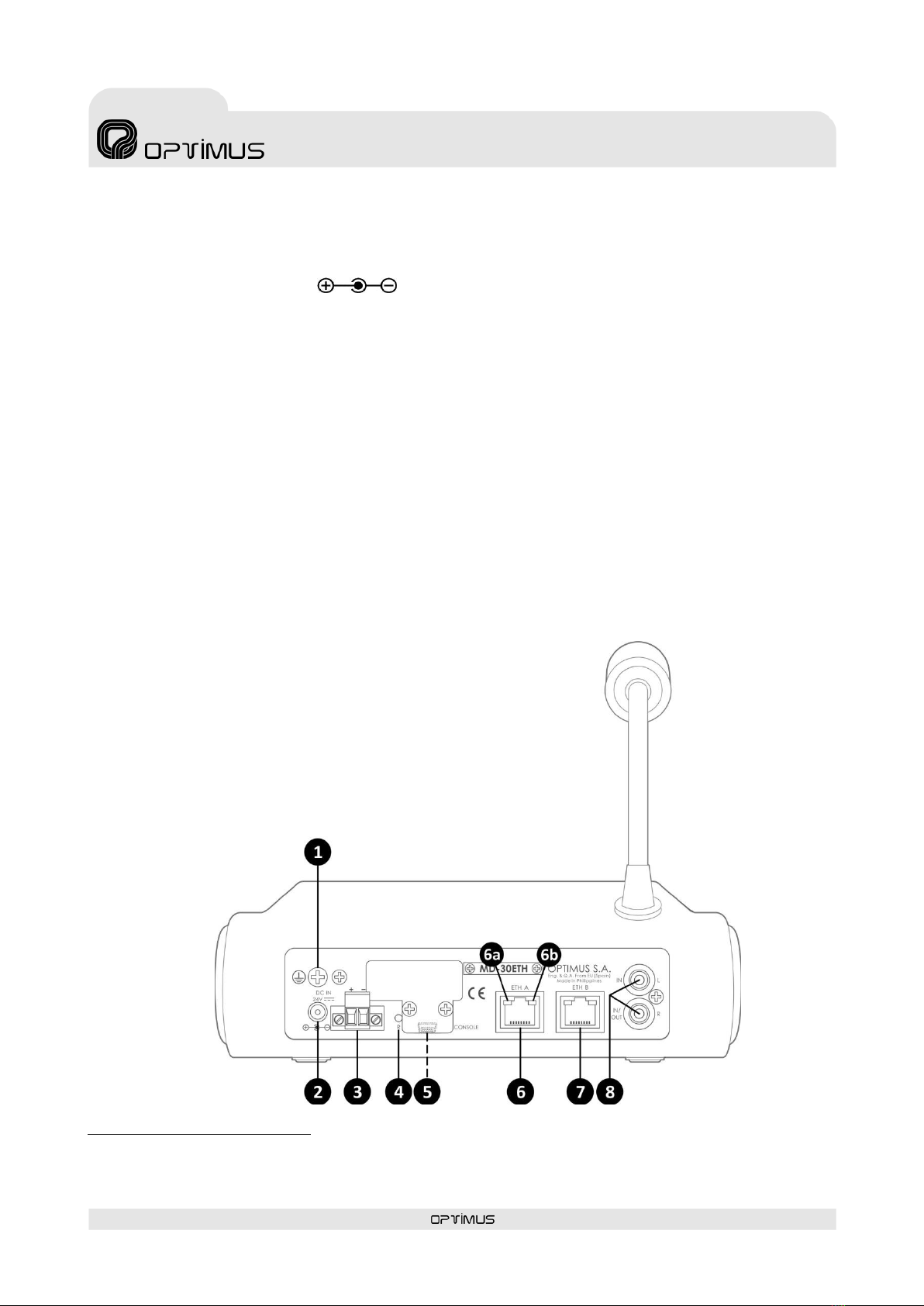
Dual Ethernet connection for installations with redundant
network systems
2 Power supplies (one primary and one secondary) for
redundant installations
Monitoring the operation of the unit via Call Point
software and/or basic TELNET functions.
Configuration of the IP address in Flash memory via
software.
Constant notification (IP) of the status of the equipment
via a Heart Beat signal
18 configurable keys: zone selection, group selection or
pre-recorded message activation (housed in the
COMPACT audio matrix or in the MD-30ETH itself). The
functionalities of these keys are configured via the Call
Point software.
Capsule surveillance.
Internal status surveillance.
Primary and secondary power supply surveillance.
Key for repeating the last live voice message.
Announcements with or without a pre-announcement
tone (Gong).
Gong that can be personalised.
Allows connecting a music source, sending the music
programme via IP.
LED alarm indicator.
Monitor speaker.
POE (under special order).
Configurable input contacts (under special order).
2. FRONT VIEW
(1) Microphone
(2) Keys 1 to 18
Depending on the configuratio n of the microphone desk,
keys 1 to 18 are used for selecting a zone, selecting a group or
activate a pre-recorded message.
a) Selection of zones: A zone is assigned to the key.
When the key is pressed, the assigned zone will be pre-
selected and the LED will illuminate. When a live voice
message, pre-recorded message o repetition is activated,
the message will be broadcast in that zone.
b) Selection of the group: A group is assigned to the key.
When the key is pressed, the assigned group will be pre-
selected and the LED will illuminate. When a live voice
message, pre-recorded message o repetition is activated,
the message will be broadcast in that group.
c) Pre-recorded message activation: A pre-recorded
message is assigned to the key. When the key is pressed,
the pre-recorded message is sent to the zones or groups
that have previously been selected. The assignment of
the message to the key must be done using the Call Point
software.
(3) Monitor speaker
(4) REPEAT Key
Key for repeating the last live voice message that was sent.
(5) TALK Key
Is used to send live voice announcements. First the zones you
wish to reach with the message must be selected. It must
remain pressed while talking.
(6) GONG+TALK Key
Is used to send live voice announcement preceded by a gong.
First the zones you wish to reach with the message must be
selected. It must remain pressed while talking
(7) ALL CALL / CLEAR Key
When pressed, it selects all the zones to carry out a general
call (ALL CALL).
When pressed, if there are selected zones or groups, the
selection is cleared (CLEAR).

MD-30ETH version 3.2.001
6
Microphone desk
with ethernet connection
MD-30ETH
(8) GENERIC FAULT indicator
Alarm indicator in the system
(9) CPU FAULT indicator
Internal error indicator of the application.
(10) POWER indicator
Indicates that power is applied to the paging desk.
(11) TALK / REPEAT indicator
Illuminates when TALK or GONG+TALK is pressed, indicating
that you can begin speaking. When the REPEAT key is
pressed, it indicates that the repeat message is playing.
(12) GONG indicator
It indicates that the paging desk is generating the GONG.
(13) BUSY indicator
When lit, it indicates that the system is busy.
(14) MIC LEVEL indicator
Indicates the audio level of the microphone or the repeat
message that is playing. The LED marked as Peak indicates
that the signal is saturated. This LED should never illuminate.
Figure 1

MD-30ETH version 3.2.001
7
Microphone desk
with ethernet connection
MD-30ETH
3. REAR VIEW
(1) Ground connection
(2) 24 VDC secondary
1
power supply
Use a Power Jack IEC 60130-10 Type A connector (outer diameter = 5.5 mm, inner diameter = 2.1 mm).
(3) 24 VDC primary power supply
(4) RESET push-button
Resets the unit back to its factory settings.
(5) CONSOLE connector
Mini USB connector. Allows monitoring the system. Only specialised personnel.
(6) Connector ETH A
Is used to connect the paging desk to the IP network.
(6a) SPEED indicator (yellow LED):
Speed of the network. Indicates a speed of 100 Mbps when lit. The light extinguished indicates a network speed of 10 Mbps (it
is highly recommended to use a transmission speed of 100 Mbps).
(6b) LINK/ACTIVITY indicator (green LED):
When lit indicates it is connected to the network. When flashing it indicates that data is being sent or received.
(7) Connector ETH B
Is used in a redundant network as a secondary connection to the IP
network.
(8) Connector IN “L” and IN/OUT “R”
RCA type connectors. Allow connecting a music source using the MD-
30ETH as a way to input analogue audio and send this music
programme via IP through the ETH connectors. To connect follow
section 4.5.
Through the Call Point software, the "R" connector can be converted
into a 0dB recording output to record, in an external system, the live
vice announcements, repetitions and pre-recorded messages sent from
the desk. To connect it follow the section 4.6.
1
The power supply inputs have been doubled; therefore, if required by the safety standards, two independent power supplies may
be connected.
Figure 2

MD-30ETH version 3.2.001
8
Microphone desk
with ethernet connection
MD-30ETH
4. CONNECTIONS
4.1.Primary power supply
4.2.Secondary power supply
4.3.Ethernet connection
Connection to the
Ethernet switch
24V DC
Power supply
I924UP
(Not included)
24V DC
Power supply
I924K25
(Not included)
POWER JACK PLUG CONNECTOR
IEC 60130-10 Type A,
outer diameter = 5.5mm,
inner diameter = 2.1mm

MD-30ETH version 3.2.001
9
Microphone desk
with ethernet connection
MD-30ETH
4.4. Connection in installations with a redundant Ethernet network
4.5.Connection of a music source to the paging desk
4.6.OUT recording connection
Conexión Ethernet
al switch 1
Fuente
musical
Conexión Ethernet
al switch 2
Sistema de
grabación

MD-30ETH version 3.2.001
10
Microphone desk
with ethernet connection
MD-30ETH
5. PLACEMENT OF THE BATTERY
For the management and maintenance of files, the equipment incorporates an RTC (Real-time clock) whose function is to maintain
the current time. To keep the RTC powered even if the equipment is turned off, we must place a 3V lithium battery type CR2032
supplied with the equipment
It is advisable to replace the equipment battery at least every 5 years.
Battery placement procedure:
Disconnect the equipment and remove1)
the four fixing screws from the bottom.
Handling batteries properly:
•Warning! Improper use of battery may lead to explosion. Replace the batteries with the same or equivalent type only.
•Batteries may endanger life if swallowed. If a battery is swallowed, seek medical assistance immediately.
•Before inserting the batteries, check whether the contacts in the device and batteries are clean and, if necessary, clean
them.
•Only use new batteries.
•Do not use rechargeable batteries.
•Never try to recharge normal batteries. There is a risk of explosion!
•Never expose batteries to heat sources (e.g. radiators) or direct sunlight. There is an increased risk of leakage!
•Never short-circuit the batteries.
•Never throw batteries into a fire.
•Do not disassemble or deform batteries.
•If the equipment is not going to be used for long periods, remove the battery.
•Remove leaking batteries from the device immediately. If battery acid leaks out it is essential to avoid contact with the skin,
eyes and mucous membranes! If the acid does come into contact with skin, immediately rinse the affected areas with
plenty of clear water and consult a doctor immediately. There is a risk of acid poisoning and acid burns!
•Remove exhausted rechargeable battery from the device immediately! There is an increased risk of leakage.
•Do not throw used batteries into the household waste. The batteries must be deposited in a collection point for used
batteries.

MD-30ETH version 3.2.001
11
Microphone desk
with ethernet connection
MD-30ETH
Remove the side covers and carefully separate the upper case from the lower2)
case, lifting it about 10 cm and allowing access to the battery holder.
Insert the battery respecting the polarity indicated in the attached drawing.3)
Assemble and reconnect the equipment.4)

MD-30ETH version 3.2.001
12
Microphone desk
with ethernet connection
MD-30ETH
6. COMMISSIONING THE UNIT
To commission the paging desk we must send configurations to it via an ethernet connection. Accomplishing this requires a PC
equipped with a network card and connected to the MD-30ETH unit through a switch or directly using a network cable. The PC
must have the Call Point software installed.
1. Place the battery (see section 5. PLACEMENT OF THE BATTERY) and make the connections between units.
2. Apply power to the units.
3. Via the Call Point software, configure the parameters of the MD-30ETH and send the settings to the unit.
6.1. Configuration of the MD-30ETH network address
To change the unit's network settings by default, carry out the following:
1. From the PC, open a browser, enter the IP address for the unit and press
INTRO. By default the IP address is 10.1.1.1. Warning: The range of IP ad-
dresses for the unit and the PC must match. Otherwise, the network settings
of the PC must be changed first in order to place it within the range of the
unit (for example, the PC could have an IP address of 10.1.100.152).
2. Enter the user name optimax, the password
1933 and click on the Login button.
WARNING
To send configurations to the unit requires having the unit and the PC within the same IP address range. The unit's
network addresses and those set via the configuration software must match.
By default, the network configurations of the unit are the following:
IP ADDRESS: 10.1.1.1
NETMASK: 255.0.0.0
GATETEWAY: 0.0.0.0 (without Gateway)
If you wish to assign a different network address to the paging desk, other than the one established by default, refer to
the following section 6.1. Configuration of the MD-30ETH network address .

MD-30ETH version 3.2.001
13
Microphone desk
with ethernet connection
MD-30ETH
3. Click on Network.
4. Modify the network pa-
rameters as desired (IP,
Netmask and Gateway)
and click on the Change
Network Settings button
to apply the changes.
The equipment will
reboot automatically.
7. TRANSFER OF PRE-RECORDED MESSAGES TO THE MD-30ETH
The paging desk incorporates an internal Micro SD memory with a capacity of 15 GB to store audio files to be used as pre-recorded
messages.
To save files in this internal memory requires a PC with the Call Point software installed and equipped with a network card, and
connected to the MD-30ETH unit through a switch or directly using a network cable (see section 6. COMMISSIONING THE UNIT).
The allowed audio file formats are wav, ogg and mp3.
Follow the Call Point software user manual to copy the files to the Micro-SD memory of the MD-30ETH.

MD-30ETH version 3.2.001
14
Microphone desk
with ethernet connection
MD-30ETH
8. OPERATIONS
8.1.Sending a live voice announcement to
one or several zones or groups
1 Select the keys corresponding to the zones and groups
where you wish to send the announcement. When
pressed, the indicator light corresponding to each key
must be lit.
2 Press and hold GONG+TALK (or TALK).
3 You can begin speaking when the blue TALK LED
illuminates.
4 To finish the broadcast, release the GONG+TALK (or
TALK).
8.2.Sending a pre-recorded message to one
or several zones or groups
1. Select the keys corresponding to the zones and groups
where you wish to send the message. When pressed, the
indicator light corresponding to each key must be lit.
2. Press the key assigned to the pre-recorded message you
want to send. The message starts to play.
While it is playing, the key light stays on.
If you want to stop the message before it ends, press the
key corresponding to the message again. The indicator
light should go out.
8.3.Making a general call (ALL CALL)
1. Press the ALL CALL key to select all the zones
simultaneously.
2. Then, press and hold the GONG+TALK (or TALK) to make
a live voice announcement, press the REPEAT key to send
the repeat of the last message or press a key assigned to
a pre-recorded message.
8.4.Repeat function
The microphone desk incorporates a function that enables to
repeat the last live voice message that was sent.
To turn this function on:
1 Select the keys corresponding to the zones and groups
where you wish to send the repeat message. When
pressed, the indicator light corresponding to each key
must be lit.
2 Select the REPEAT key. The TALK/REPEAT indicator light
remains illuminated while the message is being repeated.
You can stop a repeat message that is being played by
pressing the REPEAT key again.
8.5.ALL CALL/CLEAR function
When the ALL CALL / CLEAR key is pressed, all the zones and
groups of the microphone desk will be selected.
If the ALL CALL / CLEAR key is pressed again, any previous
zone or group selection will be cleared.
ALL CALL / CLEAR is also used to accept an alarm: The
microphone desk incorporates a buzzer that generates an
acoustic signal each time an alarm is received. The acoustic
indication is a buzzing sound that lasts 10 seconds and is
periodically repeated every 20 seconds until the alarm is
accepted. Keep the ALL CALL/CLEAR key pressed for three
seconds to accept the alarm and stop the buzzer.
9. SYSTEM ALARMS
The microphone desk incorporates several alarm indicators:
GENERIC FAULT indicator light: Front yellow LED. Illuminates when the microphone desk receives one or several alarms from
the system or when an alarm is generated by the desktop itself.
CPU FAULT indicator light: Front yellow LED. Illuminates when the microphone desk detects an internal application error
(firmware).
Acoustic alarm indicator (buzzer): Acoustic indication that is generated by the unit when it receives an alarm. The acoustic
indication is a buzzing sound that lasts 10 seconds and is periodically repeated every 20 seconds until alarm is accepted (see
section 8.5.ALL CALL/CLEAR function. This acoustic indication may be activated or deactivated through the configuration
software.

MD-30ETH version 3.2.001
15
Microphone desk
with ethernet connection
MD-30ETH
10. DIMENSIONS
11.TECHNICAL CHARACTERISTICS
MD-30ETH
Inputs
2 Ethernet (RJ45) and 1 music programme input (RCA connectors)
Outputs
One 0 dB recording output (RCA connector)
Power supply
24 VDC
Consumption
500 mA
Weight
1.7 Kg
Finishes
Paging desk: RAL7021 Bayblend plastic
Flexo MICROPHONE
Capsule
Dynamic
Polar diagram
Unidirectional
Frequency response
150 Hz 12 kHz
Sensitivity
2.2mV/Pa/1kHz
Output impedance
500 Ohm 30% (at 1kHz)
Material
Aluminium

MD-30ETH version 3.2.001
16
Microphone desk
with ethernet connection
MD-30ETH
12. NETWORK SPECIFICATIONS IN A COMPACT SYSTEM
COMPACT public address system supports audio and control data Communications through Ethernet and IP.
Since it works on levels 3 and 4 of the OSI scale, COMPACT protocol supports Communications through routers (IP protocol) by
means of the configurations of the gateways and subnetwork masks. Thanks to these features, COMPACT system can work on both
LANs and WANs.
The protocols used by the COMPACT system allow working without problems in networks where the different public address
systems are located in different VLANs.
Communications it uses are:
TCP/IP for control communications between different devices.
UDP Unicast for the audio broadcasting from a local IP microphone to a local COMPACT matrix (point to point
communication).
UDP Multicast for the audio broadcasting from a global IP microphone to the COMPACT matrixes (point to multipoint
communication).
VoIP: COMPACT matrix allows to work also like a receiving VoIP terminal (one call each time) as following standards:
-Call establishing according to SIP RFC 3261
-For zones selection --> DTMF through SIP INFO or RFC 2833
-Supports calls “Peer to Peer” or through Proxy server
-RTP audio (Unicast/Multicast)
-Supported audio codecs in VoIP calls:
G711 (µ-law + A-law)
G722
L16 (16 bits/44.1KHz)
For a properly operation as a VoIP terminal, network has to be configured according to the defined specifications for IP
telephony.
Ports for communications standard services used in COMPACT systems:
Protocol
Port
Others
TELNET
TCP (Unicast)
23
FTP
TCP (Unicast)
21
Ports for the SECURE communication services used in the COMPACT system:
Protocol
Port
Others
SSH
TCP (Unicast)
22
FTPS
TCP (Unicast)
990

MD-30ETH version 3.2.001
17
Microphone desk
with ethernet connection
MD-30ETH
For operating with COMPACT protocol, the following parameters must be met:
Protocol
Multicast address
Port
Others
Control
TCP (Unicast)
10102,10103,10104
Unicast Audio (point
to point)
UDP (Unicast)
Between 6000 and 32000
Selected by configurations.
Multicast audio
(point to multipoint)
UDP (Multicast)
Between 239.0.0.0 and
239.255.255.255
Between 6000 and 32000
Prefixed Multicast
addresses (static) for each
global sender.
Selected by configurations.
Configuration
UDP (Unicast)
10001
Configurations from PC.
Integration XML
TCP (Unicast)
27000
Integration to PC
(optional).
Integration JSON
TCP (Unicast)
28000
Direct integration and
control to equipment.
Integration SNMP
UDP (Unicast)
161
162 (TRAPS)
Integration SIP
UDP (Unicast)
5060 (Control)
7078 (RTP Audio)
It is strongly recommended to apply QoS policies (quality of service), both at the network level and at the equipment level, es-
tablishing priorities between the different types of traffic according to the following table:
Priority
Protocol
HIGH
Global Audio
UDP (Multicast)
Local Audio
UDP (Unicast)
Integration SIP
UDP (Unicast)
MEDIUM
TELNET
TCP (Unicast)
SSH
TCP (Unicast)
Control
TCP (Unicast)
Configuration
UDP (Unicast)
Integration XML
TCP (Unicast)
Integration JSON
TCP (Unicast)
Integration SNMP
UDP (Unicast)
LOW
FTP
TCP (Unicast)
FTPS
TCP (Unicast)

MD-30ETH version 3.2.001
18
Microphone desk
with ethernet connection
MD-30ETH
Backbone network specifications
-Bandwidth:
o3kbps of control data for each equipment and 1kbps additionally for each alarm.
Example:
Matrix with 5 alarms 3kbps (data) + (5 alarms * 1kbps) = 8kbps
Paging console with 2 alarms 3kbps (data) + (2 alarms * 1kbps) = 5kbps
Total data=13kbps
oStreaming audio channel according to the audio format protocol (configurable):
RAW PCM 48KHz / 16 bits: 768kbps for each audio channel.
RAW PCM 24 KHz / 16 bits: 384kbps for each audio channel.
RAW PCM 16 KHz / 16 bits: 256kbps for each audio channel.
RAW PCM 8 KHz / 16 bits: 128kbps for each audio channel.
RTP L16 RAW PCM 44KHz / 16 bits: 705.6kbps for each audio channel.
RTP G.711 µ-LAW 8KHz / 8 bits: 64kbps for each audio channel.
RTP G.711 A-LAW 8KHz / 8 bits: 64kbps for each audio channel.
-Note: Control (without alarms) + number of simultaneous channel * Type of format protocol = Bandwidth
oRAW PCM 48KHz, 4 channels, 100 equipment(3kbps * 100Eq.) + (4CH * 768kbps) = 3.4 Mbps
oRAW PCM 48KHz, 4 channels, 50 equipment. (3kbps * 50Eq.) + (4CH * 768kbps) = 3.2 Mbps
oRTP G.711 A-LAW 8KHz, 4 channels, 100 equipment.(3kbps * 100Eq.) + (4CH * 64kbps) = 0.56 Mbps
oRTP G.711 A-LAW 8KHz, 4 channels, 50 equipment. (3kbps * 50Eq.) + (4CH * 64kbps) = 0.4 Mbps
Specifications of the Switch/Router for LAN and WAN networks
-Protocols:
oTCP/IP For control/signalling/monitoring status.
oUDP Unicast for Local Audio.
oUDP Multicast for Global Audio.
-Multicast snooping:
oMulticast filtering.
oIGMP v2.
-For large installations:
oMulticast Routing (Spanning Tree).
oCapable to handle TOS (Type Of Service).
Table of contents
Languages:
Other Opvimus Microphone manuals