Page 3
1.0 Description Safety Breakaway Coupling
1.1 Area of use
The Safety Breakaway Coupling (NTS-PU) can be used in loading arms, hose- and pipelines for the
transfer of fluids or gas. A typical application is the unintended tank truck/railcar/aircraft pull-off or
the drifting away of a barge or ship.
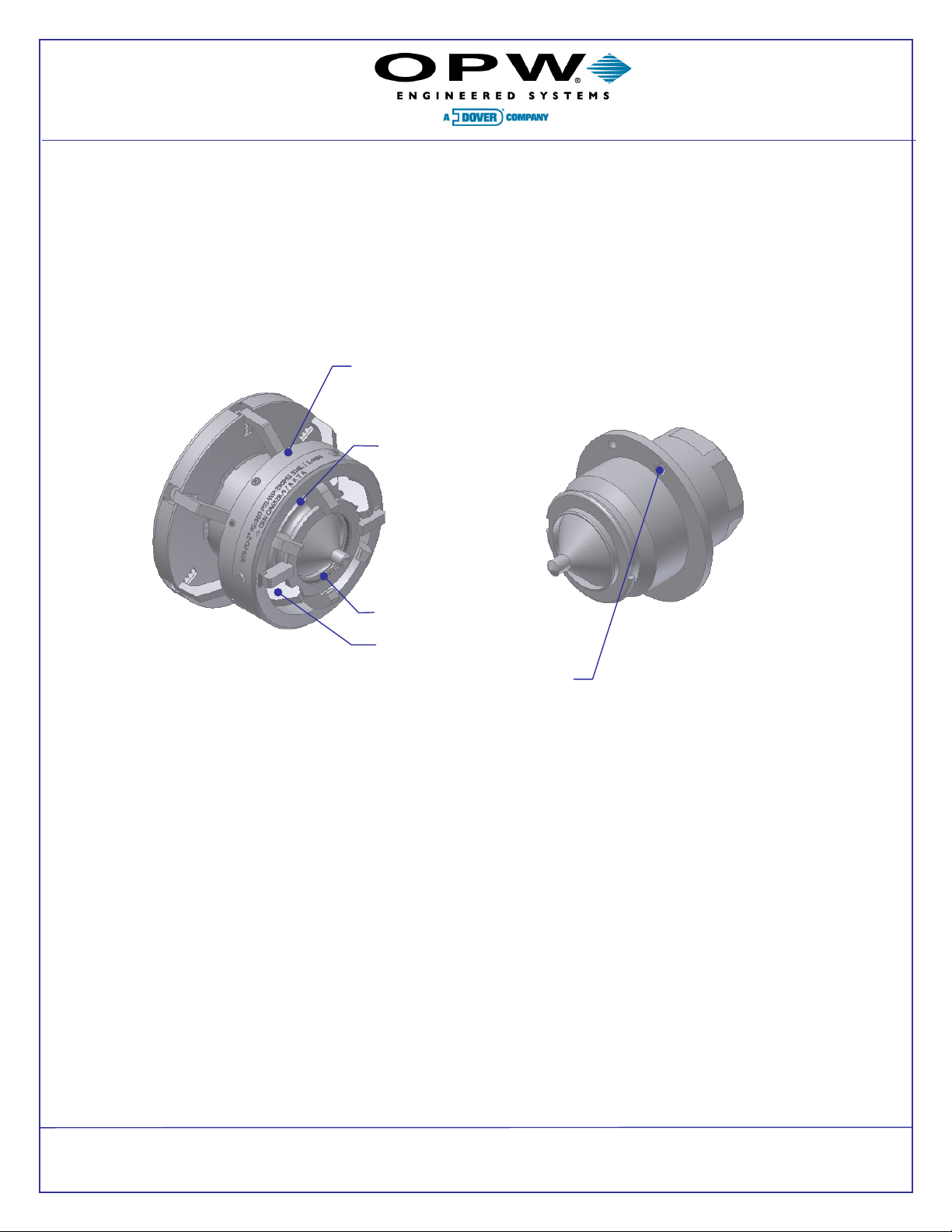
1.2 Design
Both halves of this emergency coupling are equipped with non returning, spring loaded valves; they
are held together by a fast coupling connection. Separation is triggered by a pulling force via the
hose or loading arm. The separation force is individually preset for max. protection of the hose
line.
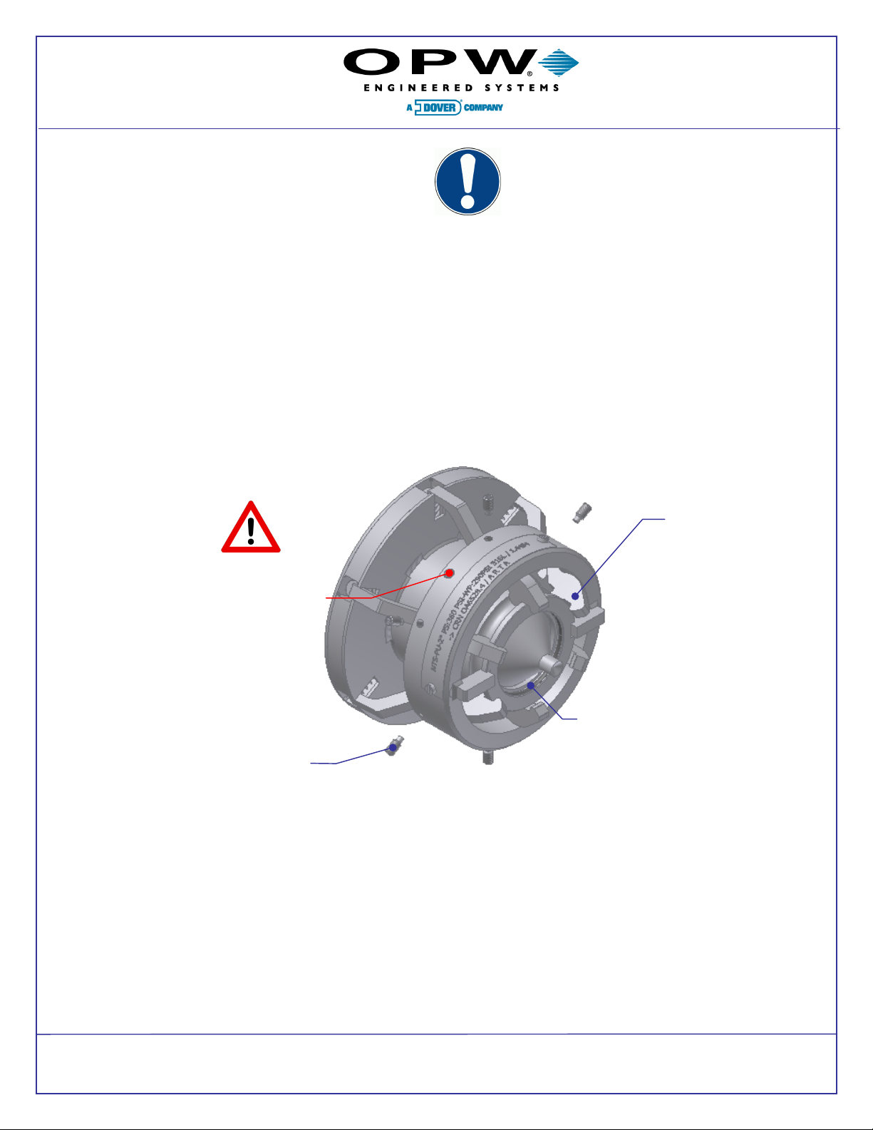
1.3 Function
In the mounted status the NTS-PU is open and allows for free flow. If a tensile force exceeds the
preset value the two halves separate. The valves instantly close on both ends to prevent spillage.
The separation does not result in the destruction of parts (shear pins); no spare parts or special
tools are required to instantly reassemble it after depressurizing and draining the hose line.
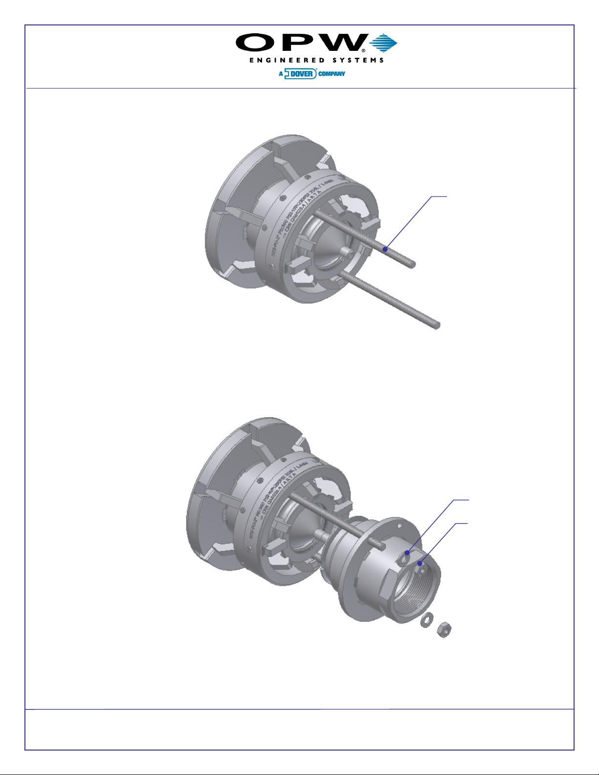
1.4 Advantages
•Working in any direction (angle)
•Built-in possible in both directions
•Easy reassembly after separation
•Mounting: tighten mounting screws, push 2 halves together and remove the
mounting screws
•Cable-free activation
•Fully functional immediately after being built in; no further activation required
•Spare-part-free, non-destructive separation
•No shear pins involved and no destruction.
•Easily reassembled w/o tools or spare parts
•Ideal for LPG transfer lines