INDEX
INDEXINDEX
INDEX Page
0.- Des ription .........................…………………………………..……................................. 2
1.- Handling ..................................………..............................…………………………….. 2
2.- Installation .................................………..................................................................... 4
3.- A tuators .....................................………................................................................... 6
4.- Maintenan e .....................................……….............................................................. 6
4.1.- Gland pa king repla ement and sleeve …….………................................... 7
4.2.- Lubri ation ......………………...…....…….................................................... 8
5.- Storage …………................................…..………....................................................... 9
6.- Parts list & drawing ..................................……………………………………..…......... 10
0.- DESCRIPTION
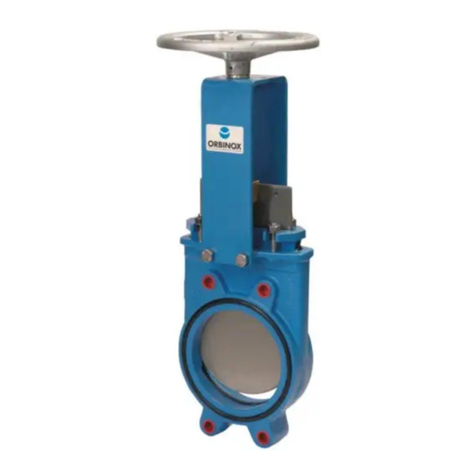
The BR model knife gate is a bi-dire tional valve and onsequently it an be installed without
onsidering the flow dire tion.
This valve is designed for general industrial servi e appli ations. The design of the body and seat
assures non- logging shut-off with suspended solids.
The BR valve omplies with the following European dire tives:
- DIR
DIR DIR
DIR 2006
20062006
2006/
//
/42
4242
42/EC (ma hines)
/EC (ma hines)/EC (ma hines)
/EC (ma hines)
- DIR 97/23/EC (PED)
DIR 97/23/EC (PED)DIR 97/23/EC (PED)
DIR 97/23/EC (PED)
Fluid: Group 1 (b), 2 (Cat. I, mod.A)
It may also omply with the dire tive:
DIR 94/9/EC (Explosive Atmospheres)
DIR 94/9/EC (Explosive Atmospheres)DIR 94/9/EC (Explosive Atmospheres)
DIR 94/9/EC (Explosive Atmospheres)
The BR valve may omply with the dire tive regarding equipment and prote tive systems for their
use in explosive atmospheres. In these ases, the logotype shall appear on the identifi ation
label of the valve. This label shows the exa t lassifi ation of the zone where the valve an be
used. The user will be liable for its use in any other zone.
This dire tive only applies in the following atmospheri onditions:
0,8 bar ≤ P ≤ 1,2 bar
-20ºC/-4Fº < T < 60ºC/140Fº
Any in rease in temperature due to fri tional warmth is negligible, sin e the relative speed of
the moving parts is extremely low.
The risk analysis asso iated to this dire tive does not take into a ount the fluid that goes
through the valve, even when su h fluid produ es an explosive atmosphere. The user must take
into a ount the risks that the fluid generates, su h as:
-heating of the valve surfa e.
-generation of ele trostati harges aused by displa ement of the fluid.
-sho k waves aused by the installation (water hammer), internal rashes generated by the
pellets or the risks due to foreign bodies sus eptible of being present in the installation.
1.- HANDLING
The valves are pa ked a ording to the appropriate transport standards. If you re eive a shipment with
damaged pa kaging, please inform the transport ompany in writing and onta t your Orbinox
representative.
