EK
INDEX Page
0. - Description .........................………............................... 2
1. - Handling ..................................………......................... 2
2. - Installation .................................………........................ 3
3. - Actuators .....................................………...................... 5
4. - Maintenance .....................................………................ 6
4.1. - Gland packing replacement …….………............... 6
4.2. - Seal replacement ......………....…....…….............. 7
4.3. - Lubrication …………………….……………..……. 8
5. - Storage …………................................…..……….......... 8
6. - Parts list & drawing ..................................……..…........ 9
0.- DESCRIPTION
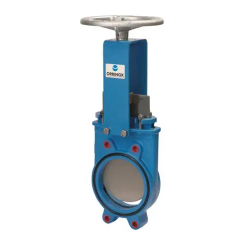
The EK model knife gate is a uni-directional wafer valve designed for general industrial service
applications. The design of the body and seat assures non-clogging shut-off with suspended solids.
The EK valve complies with the following European directives:
-DIR 98/37/EC (machines)
-DIR 97/23/EC (PED) Fluid: Group 1 (b), 2 (Cat. I, mod.A)
It may also comply with the directive:
-DIR 94/9/EC (Explosive Atmospheres)
The EX valve may comply with the directive regarding equipment and protective systems for their
use in explosive atmospheres. In these cases, the logotype shall appear on the identification
label of the valve. This label shows the exact classification of the zone where the valve can be
used. The user will be liable for its use in any other zone.
This directive only applies in the following atmospheric conditions:
0,8 bar ≤P ≤1,2 bar
-20ºC < T < 60ºC
Any increase in temperature due to frictional warmth is negligible, since the relative speed of
the moving parts is extremely low.
The risk analysis associated to this directive does not take into account the fluid that goes
through the valve, even when such fluid produces an explosive atmosphere. The user must take
into account the risks that the fluid generates, such as:
- heating of the valve surface.
- generation of electrostatic charges caused by displacement of the fluid.
- shock waves caused by the installation (water hammer), internal crashes generated by the
pellets or the risks due to foreign bodies susceptible of being present in the installation.
1.- HANDLING
When handling an Orbinox valve please pay attention to the following points:
•Do NOT attach lifting gear to the valve actuators or gate guards.
They are not designed to bear the weight, and could easily be damaged.
•Do NOT lift the valve by the valve bore.
This can cause damage to the seating surfaces and seals.
Ideally when using lifting gear to move an Orbinox valve, it should be supported by two or more
eyebolts screwed into the tapped fixing holes in the valve body.
