3.-ACTUATORS
3.1.-Handwheel
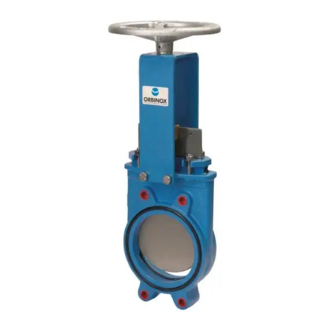
To open the valve turn the handwheel (11) anticlockwise. To close turn the handwheel
clockwise.
3.2.-Pneumatic
Valves are usually supplied with a double acting pneumatic actuator although, upon
request, we can supply single-acting actuators. In both cases, the inlet air pressure should
be, between 3,5 to 10 Kg/cm2.
It is essential for a good maintenance of the cylinder that air should be well dried, filtered
and lubricated.
It is recommended to actuate the cylinder 3-4 times before the start up, once it is installed
in the pipeline.
3.3.-Electric actuator
Depending on the type or make of the electric actuator, specific instructions (i.e. a
manufacturer’s manual) will be supplied.
4.-MAINTENANCE
To avoid personal injury or damage to property from the release of process fluid:
-Those in charge of handling and maintenance of the valve must be qualified and
trained in valve operations.
-Use appropriate personal protection equipment (gloves, safety shoes, etc).
-Shut off all operating lines to the valve and place a warning sign.
-Isolate the valve completely from the process.
-Release process pressure.
-Drain the process fluid from the valve.
The only maintenance required is to change the gland packing (4) or the seal (3) if the valve is
a resilient seated type.
The life of these elements will depend on the working conditions of the valve such as:
pressure, temperature, abrasion, chemical action, number of operations, etc.
4.1. -Replacement of the gland packing (4):
Although the design of the valve bonnet allows the stuffing box of the bonnet to be sealed
from below, we advise that the valve is depressurised prior to beginning any maintenance.
1) Open the valve fully, to tighten the stem against the stuffing box.
2) Remove gate guards (if the valve has them).
3) Loosen the nuts of the gland follower (5) and remove it. (Photo 1)
4) Remove the old packing (4) and clean the stuffing box.
5) Insert the new packing rings (4), making sure that the ring joints alternate (the first on
one side of the gate, the next on the other and so on). (Photo 2)
6) Once the necessary packing rings (4) have been inserted, proceed with a steady
initial tightening, of the gland follower (5). (Photo 1)
