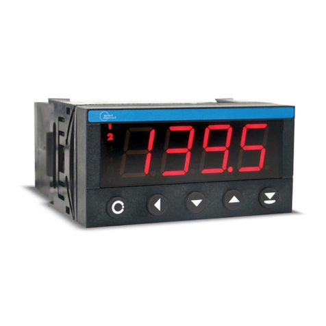
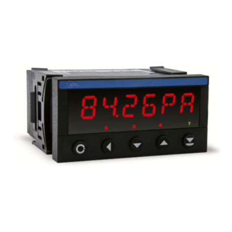
Orbit Merret OM 621BCD User manual

OM 621BCD
DIGIT PROGRAMMABLE
BCD MONITOR
ACTIVE TRANSFORMER TAPPING LEADS
USER MANUAL
NÁVOD K OBSLUZE
DIGITAL PANEL METERS
PANELOVÉ MĚŘÍCÍ PŘÍSTROJE
BARGRAPHS
SLOUPCOVÉ ZOBRAZOVAČE
LARGE DISPLAYS
VELKOPLOŠNÉ DISPLEJE
TRANSMITTERS TO DIN RAIL
PŘEVODNÍKY NA LIŠTU
PAPERLESS RECORDERS
BEZPAPÍROVÉ ZAPISOVAČE
PLC
WARRANTY
YEARS
148.9~C
-263mm
453mV

148.9~C
-263mm
453mV
TECHNICAL DATA
Measuring instruments of the OM series conform to the European regulation //EU and //EU
The instruments are up to the following European standards:
EN - Electrical safety
EN - Electronic measuring, control and laboratory devices – Requirements for EMC “Industrial use”
The recorders are applicable for unlimited use in agricultural and industrial areas.
ORBIT MERRET, spol. sr.o.
Vodnanska /
Prague
Czech Republic
Tel: + -
Fax: + -
e-mail: [email protected]
www.orbit.merret.eu
SAFETY INSTRUCTIONS
Please read carefully the enclosed safety instructions and observe them!
Installation,alloperationalinterventions,maintenanceandservicemustbeperformedbyaqualifiedpersonnel
and in accordance with the attached information and safety regulations. The manufacturer is not liable for
damage caused by improper installation, configuration, maintenance, and service.
The recorder must be installed according to the respective application. Incorrect installation can cause a
malfunction, which can result in damage or accident.
The recorder uses dangerous voltages that can cause a fatal accident. Before you start solving problems
(e.g. in case of failure or disassembly), the device must be disconnected from the power supply. For safety
information the EN - + A standard must be observed.
When removing or inserting a card, observe the safety instructions and follow the recommended procedure.
During any intervention the recorder must be disconnected from the power supply.
Do not attempt to repair or modify the device. A defective recorder must be sent for repair to the manufacturer.
These devices should be safeguarded by isolated or common fuses (breakers)!
The recorder is not designed for installation in potentially explosive surroundings (Ex). Use it only outside
potentially explosive surroundings

INSTRUCTIONS FOR USE OM 621BCD | 3
148.9~C
-263mm
453mV .CONTENTS
. CONTENTS....................................
. INSTRUMENT DESCRIPTION ....................
. INSTRUMENT CONNECTION ....................
. INSTRUMENT SETTING .........................
Programming modes ...........................
Control keys function...........................
Setting the DP and the (-) sign ...................
. Guide through minimum instrument setting,
calibration...................................
. User menu ..................................
.. Internal value resetting ..................
.. Setting the limits ........................
.. Setting the data output ..................
.. Setting the analog output ................
. Configuration menu ..........................
.. Configuration mode - INPUT
Values resetting (min/max, tare) ...........
Instrument configuration .................
.. Configuration mode - CHANNELS
Channel A..............................
Mathematic functions ....................
.. Configuration mode - OUTPUT
Limits .................................
Data output ............................
Analog output ..........................
Projection on the display .................
.. Configuration mode - SERVICE
Access rights for User mode .............
Return to manufacture setting ............
Menu language .........................
New access password ...................
Instrument identification .................
. DATA PROTOCOL .............................
. ERROR STATEMENTS ..........................
. TABLE OF SYMBOLS ..........................
. TECHNICAL DATA ............................
. INSTRUMENT DIMENSIONS AND INSTALATION...
. CERTIFICATE OF GUARANTEE ..................

4| INSTRUCTIONS FOR USE OM 621BCD
148.9~C
-263mm
453mV
INSTRUMENT DESCRIPTION.
2.1 DESCRIPTION
Model OM BCD is a -digit panel monitor of serial or parallel BCD/BIN signal and montor of active transformer tapping leads,
allowing for projection of transitional status and servomotor running.
The instrument is based on a single-chip microprocessor, which guarantees accuracy, stability and easy control.
PROGRAMMABLE PROJECTION
Setting: in „CM“ you can set the type of BCD input or montor of active transformer tapping leads
Projection: -…
Control
The instrument is set and controlled by five control keys located on the front panel. All programmable settings of the instrument
are realised in two adjusting modes:
Configuration menu (hereinafter referred to as „CM“) is protected by an optional numeric code
and containis complete instrument setting
User menu may contain arbitrary programming setting defined in CM with another selective restriction change
All programmable parameters are stored in the EEPROM memory (they hold even after the instrument is switched off).
Excitation
is suitable for supplying power to sensors and transmitters. It has a galvanic separation.
Comparators
are assigned to monitor one, two, three or four limit values with relay output. The limits have adjustable hysteresis
within the full range of the display as well as selectable delay of the switch-on in the range of ..., s. Reaching the preset
limits is signalled by LED and simultaneously by the switch-on of the relevant relay.
Data outputs are for their rate and accuracy suitable for transmission of measured data for further projection or directly into
the control systems. We offer isolated RS andRS with the ASCII protocol or MessBus.
Analog outputs will find their place in applications where further evaluating or processing of measured data in external devices
is required. We offer universal analog output with the option of selection of the output type - voltage/current. The analog output
value corresponds with the displayed data and its type and range are selectable in the programming mode.
Extension

INSTRUCTIONS FOR USE OM 621BCD | 5
148.9~C
-263mm
453mV

6| INSTRUCTIONS FOR USE OM 621BCD
148.9~C
-263mm
453mV
. INSTRUMENT CONECTION
The instrument supply leads should not be in proximity of the incoming low-potential signals.
Contactors, motors with larger input power should not be in proximity of the instrument.
The leads into the instrument input (measured quantity) should be in sufficient distance from all power leads andappliances.
Provided this cannot be secured it is necessary to use shielded leads with connection to ground (bracket E).
The instruments are tested in compliance with standards for use in industrial area, yet we recommend to abide by the above
mentioned principles.
Relay parameters specified in the technical data
apply for resistance load. Upon connection of the
induction load we recommend to fit the leads to relay
A with a fuse for maximum load protection.
Grounding on terminal „E“ must be connected
at all times
L5
L1
L
N
POWER
L2
L3
L4
E
INP 0
INP 1
INP 2
INP 3
INP 4
INP 5
INP 6
INP 7
Sgn
Adr 0
Adr 1
Adr 2
GND
AO
TxD/B
GND
RxD/A
-
+
GND
INP 8
INP 9
INP 10
INP 11
INP 12
INP 13
INP 14
INP 15
INP 16
INP 17
INP 18
INP 19
INP 20
INP 21
INP 22
INP 23
17 18 19 20 21 22 23 24 25 26 27 28 29 30 31 32
1 2 3 4 5 6 7 8 9 13 14 1510 11 12 16
Excit.
+
CA B OD E F G H I J K L M N

INSTRUCTIONS FOR USE OM 621BCD | 7
148.9~C
-263mm
453mV

8| INSTRUCTIONS FOR USE OM 621BCD
148.9~C
-263mm
453mV
. INSTRUMENT SETTING
The instrument is set and controlled by control keys located on the front panel. By means of these control keys it is possible
to browse through theoperting program, to select and set the required values.
CONFIGURATION MODE USER MODE
• designated for professional service and maintenance • designated for instrument service
• complete instrument setting • may contain setting the limits, analog and
• access is password protected data output and brightness, with restriction
as
• authorization for "User mode" per the setting in"Configuration mode"
Symbols used in the instructions
DEF
Indication of manufacture pre-setting
CONTROL KEYS FUNCTIONS
MENU ENTER LEFT DOWN UP
Measuring mode
menu access optional function optional function optional function optional function
Moving around in the menu
exit the menu
without saving
move to next level back to previous
level move to next item
Setting/selecting - items
cancel setting
without saving confirm selected
item move down move up
Setting - numbers
cancel setting
without saving cancel selected
number move to higher
decade change of current
figure - down - change of current
figure - up -
1 2 T3 4 M
4285.42
Ralay status (red LED)
ON the digit is lit
OFF the digit is not lit
OFF the digit is flashing
limits with restriction
(hysteresis, delay
Function (green LED)
M Min/max. value
T Tare
Measured value (red/green LED)
the last two places may display
measuring units

INSTRUCTIONS FOR USE OM 621BCD | 9
148.9~C
-263mm
453mV INSTRUMENT SETTING .
Setting the decimal point and the minus sign
DECIMAL POINT
Its selection is performed for each quantity independently in the „Channels“ menu. Upon modification of the number to be
adjusted transition behind the highest decade is performed by the control key , when the decimal point starts flashing.
Positioning is performed by .
MINUS SIGN
Its selection is performed independently for every item. The sign is set on the highest decade by the control key andit is
placed between the digits „“ and„“. Confirmation is made by pressing .
Access into the configuration mode
PASSW .
CHANEL.
SERVIC.
OUTPUT.
0000
shift left
OK
w/o saving 0,1,2…
9,8,7…
+
The code is always preset from
manufacture to . In case of loss
of access password it is possible to use
universal access code ""
INPUTS

10 | INSTRUCTIONS FOR USE OM 621BCD
148.9~C
-263mm
453mV
. GUIDE THROUGH MINIMUM INSTRUMENT SETTING
uAccess into the „Configuration menu“
0000
PASSW .
shift left
OK
w/o saving 0,1,2…
9,8,7…
+PASSW . Entering the introductory access
password
0000 Standard manufacture setting of
the access password
Setting display projection
MODE Setting the input parameters
BCD 24 Parallel BCD - bit
BIN 20 Binar - bit
BCD6-4 Serial BCD - data/ Strobe
BCD3-8 Serial BCD - data/ Strobe
BCD212 Serial BCD - data/ Strobe
B C D1 3 4 Serial BCD - data/ Strobe/
segments
TR A N SF. Transformer tapping leads
INPUTS
S E R VI C .
OUTPUT.
CHANEL.
CLEAR
CONFIG
MODE
FILTER
DEC. PT.
ADDR.
BCD 24
BIN 20
BCD212
BCD3-8
BCD6-4
TR A N SF.
B C D1 3 4
HI.CHAR
M.M. INP.
. INSTRUMENT SETTING

INSTRUCTIONS FOR USE OM 621BCD | 11
148.9~C
-263mm
453mV INSTRUMENT SETTING .

12 | INSTRUCTIONS FOR USE OM 621BCD
148.9~C
-263mm
453mV
. USER MENU
• designed for instrument service
• may contain setting limits, analog/data output and brightness with restriction as per the setting in „Configuration mode“
.. USER MENU INTERNAL VALUES RESETTING
CLEAR Instrument internal values
resetting
CL. M.M. Resetting the minimum and
maximum values, measurements
CL. MIN Resetting the minimum values
measurements
CL. MAX Resetting the maximum values
measurements
INPUTS
OUTPUT.
CLEAR CL. M.M.
CL. MIN
CL. MAX
OUTPUT. LIMIT D ATA
Setting limit,
hysteresis
anddelay
Setting the
data output
AN. OUT.
Setting the
analog
output
OUTPUT.
Setting the instrument outputs
23 . 6
INPUTS CLEA R
Internalvalue
resetting
INPUTS
Setting the instrument input
Projection of items and their accessibility
depends on the setting in „Configuration menu“,
items „RIGHTS“
Adjustable authorization of access into
items see page
. INSTRUMENT SETTING
DISP.
Setting the
display
brightness

INSTRUCTIONS FOR USE OM 621BCD | 13
148.9~C
-263mm
453mV
.. LIMITS ENTERING THE VALUES
LIM - Entering the limit values for
status evaluations
LIMIT Setting the limit for relay switch-on
- in full range of the display
HYST Setting hysteresis only in (+) values
- in full range of the display
ON. L Setting the beginning of the range
of the limit switch-on
- in full range of the display
O FF. L Setting the end of the range of the
limit switch-on
- in full range of the display
PERIOD Setting the period of the limit
switch-on
- in full range of the display
TIM E. L Setting the offset of the limit
switch-on
- in range …, s
.. DATA OUTPUT SETTING THE RATE
BAUD Setting the data output rate
(baud)
1200 Rate - Baud
2400 Rate - Baud
4800 Rate - Baud
9600 Rate - Baud
19200 Rate - Baud
38400 Rate - Baud
INPUTS
OUTPUT.
LIMIT
AN. OUT.
DATA
LIM 1
LIM 2 HYST.
LIMIT
O FF. L .
ON. L.
PERIOD
DISP. LIM 4
LIM 3
TIM E L.
INPUTS
OUTPUT.
LIMIT
AN. OUT.
DATA
BAUD
ADDR.
9600
4800
2400
1200
38400
19200
DEF
DISP.
Adjustable authorization of access into
items, see page
INSTRUMENT SETTING .
Adjustable authorization of access into
items, see page

14 | INSTRUCTIONS FOR USE OM 621BCD
148.9~C
-263mm
453mV
... DATA OUTPUT SETTING THE INSTRUMENT ADDRESS
ADDR. Setting the instrument address
- setting in range …
- manufacture setting
DEF
.. ANALOG OUTPUT SETTING THE RANGE
AN. OUT. Setting the analog output range
- the analog output is isolated and its value
corresponds with the displayed data. It is fully
programmable, i.e. it allows to assign the AO
limit points to any two arbitrary points of the
entire measuring range
AO . MIN Assigining the displayed value to
the beginning of the AO range
- range of the setting is ±
AO. MAX Assigining the displayed value to
the end of the AO range
- range of the setting is ±
.. SETTING THE DISPLAY BRIGHTNESS
BRIGHT. Setting the display brightness
100% Brightness %
0% Brightness %, display switched-off
- display switches off after approximately s
and it switches on after pressing any key
25% Brightness %
50% Brightness %
75% Brightness %
INPUTS
OUTPUT.
LIMIT
AN. OUT.
DATA
BAUD
ADDR.
DISP.
INPUTS
OUTPUT.
LIMIT
AN. OUT.
DATA
AO . MIN
AO. MAX
DISP.
0%
100%
75%
50%
25%
DEF
INPUTS
OUTPUT.
LIMIT
DISP.
DATA
BRIGHT.
AN. OUT.
. INSTRUMENT SETTING
Adjustable authorization of access into
items, see page
Adjustable authorization of access into
items, see page
Adjustable authorization of access into
items, see page

INSTRUCTIONS FOR USE OM 621BCD | 15
148.9~C
-263mm
453mV
. CONFIGURATION MENU• designated for professional service andmaintenance
• complete instrument setting
• access is protected by password or a shorting link on the input connector
• authorization for "User mode"
INSTRUMENT SETTING .
Upon delay longer than s the programming mode is automatically discon-tinued
and the instrument itself switches back to the measuring mode
23 . 6
Entering the access password
PASSW .
0000
CHANNE. CHAN. A
OUTPUT LIMIT DATA DISPAN. OUT.
S E R VI C . A CCESS R EST O R . LANG. N . P ASS . ID ENT
INPUTS CLEA R
Internal
values
resetting
Basic
instrument
setting
Configuration
of parameters
of the measu-
ring channel
MATH . FN .
Setting the
mathematic
functions
Setting the
limits, hystere-
sis and delay
Setting the
data output
Setting the
projection
Setting the
analog output
Setting the
access rights
for „User
menu“
Return to
manufacture
setting
Setting the
language
version
Change of
the access
password
Instrument
identification
INPUTS
Setting the instrument input
CHANNEL
Setting the measuring channels
OUTPUT
Setting the instrument outputs
SERVICE
Service functions
+
CONFIG.

16 | INSTRUCTIONS FOR USE OM 621BCD
148.9~C
-263mm
453mV
.. CONFIGURATION MODE INPUTS
INPUTS
S E R VI C .
OUTPUT.
CHANEL.
CLEAR
CONFIG
The basic instrument parameters are adjusted in
this menu
CLEAR Resetting the internal values of the
instrument
CONFIG Basic instrument setting
... INTERNAL VALUES RESETTING
CL. M.M. Resetting the min and max value of
the measurement
CL. MIN Resetting the minimal value of the
measurement
CL. MAX Resetting the maximal value of the
measurement
.... SETTING THE MEASURING MODE
MODE Setting the input parameters
BCD 24 Parallel BCD - bit
BIN 20 Binar - bit
BCD6-4 Serial BCD - data/ Strobe
BCD3-8 Serial BCD - data/ Strobe
BCD212 Serial BCD - data/ Strobe
B C D1 3 4 Serial BCD - data/ Strobe/
segments
TR A N SF. Transformer tapping leads
INPUTS
S E R VI C .
OUTPUT.
CHANEL.
CLEAR
CONFIG
CL. M.M.
CL. MIN
CL. MAX
INPUTS
S E R VI C .
OUTPUT.
CHANEL.
CLEAR
CONFIG
MODE
FILTER
DEC. PT.
ADDR.
BCD 24
BIN 20
BCD212
BCD3-8
BCD6-4
TR A N SF.
B C D1 3 4
HI.CHAR
M.M. INP.
. INSTRUMENT SETTING

INSTRUCTIONS FOR USE OM 621BCD | 17
6.
148.9~C
-263mm
453mV
Input BCD 24 BIN 20 BCD6-4 BCD3-8 BCD212 BCD134 TRANSF.RM.
Inp0 A0 000001 A A0 A0 A Tap 1
Inp1 B0 000002 B B0 B0 B Tap 2
Inp2 C0 000004 C C0 C0 C Tap 3
Inp3 D0 000008 D D0 D0 D Tap 4
Inp4 A1 000016 x A1 A1 Segment 0 Tap 5
Inp5 B1 000032 x B1 B1 Segment 1 Tap 6
Inp6 C1 000064 x C1 C1 Segment 2 Tap 7
Inp7 D1 000128 x D1 D1 Strobe Tap 8
Inp8 A2 000256 x x A2 x Tap 9
Inp9 B2 000512 x x B2 x Tap 10
Inp10 C2 001024 x x C2 x Tap 11
Inp11 D2 002048 x x D2 x Tap 12
Inp12 A3 004096 x x x x Tap 13
Inp13 B3 008192 x x x x Tap 14
Inp14 C3 016384 x x x x Tap 15
Inp15 D3 032768 x x x x Tap 16
Inp16 A4 065536 Strobe 0 Strobe 01 Strobe 012 x Tap 17
Inp17 B4 131072 Strobe 1 Strobe 23 Strobe 345 x Tap 18
Inp18 C4 262144 Strobe 2 Strobe 45 x x Tap 19
Inp19 D4 524288 Strobe 3 x x x Tap 20
Inp20 A5 E.Over. Strobe 4 x x x Tap 21
Inp21 B5 E.Over. Strobe 5 x x x Tap 22
Inp22 C5 E.Over. x x x x Tap 23
Inp23 D5 E.Over. x x x x Tap 24
Sgn minus minus minus minus minus minus servo
Adr0 yes yes yes yes yes yes no
Adr1 yes yes yes yes yes yes no
Adr2 yes yes yes yes yes yes no
Differences in projection when in mode „TRANSFORMER“
- if tap or higher is switched in BCD mode, all relays become energised
- if no input is switched on, the display shows “ ---- “
- when input is switched on, the display shows „“. Number „“ represents the number of the tap
- when inputs are switched on, the display shows “ [] “. Number represents the number of the tap, that has been switched on*
- when or more inputs are switched on, the display shows “ XXXX “
- when Sgn is on, the display shows “-ZZZZ-”. ZZZZ represents what was on the display
INSTRUMENT SETTING .
When device is fitted with sensor excitation, input Adr is not available

18 | INSTRUCTIONS FOR USE OM 621BCD
148.9~C
-263mm
453mV
.... SETTING THE INPUT FILTER
FILTER Setting the range or type of
measurement
- setting range: …
- numeric value of the filter represents
the duration of time (in ms) of a pulse
that is to be recognised as valid by the
system
.... SETTING OF DEVICE ADDRESS
ADDR. Setting the indtrument address
IMMED. Input data are displayed regardless
of address
ADR. 1 Address
- setting range: Adr. …
.... SETTING THE DECIMAL POINT
FORMAT Setting the decimal point
- the instrument allows for classic projection of a
number with placement of the decimal point
(/,/,/,/,/
,)
INPUTS
S E R VI C .
OUTPUT.
CHANEL.
CLEAR
CONFIG FILTER
MODE
DEC. PT.
ADDR.
20
HI.CHAR
M.M. INP.
IMMED.
ADR. 1
ADR. 4
ADR. 3
ADR. 2
ADR. 6
ADR. 5
ADR. 7
DEF
INPUTS
S E R VI C .
OUTPUT.
CHANEL.
CLEAR
CONFIG
ADDR.
MODE
DEC. PT.
FILTER
HI.CHAR
M.M. INP.
000000
00000.0
00.0000
000.000
0000.00
0.00000
DEF
INPUTS
S E R VI C .
OUTPUT.
CHANEL.
CLEAR
CONFIG
DEC. PT.
MODE
ADDR.
FILTER
HI.CHAR
M.M. INP.
When setting the excitation, the range is limited
to Adr …
. INSTRUMENT SETTING

INSTRUCTIONS FOR USE OM 621BCD | 19
148.9~C
-263mm
453mV
.... SETTING OF UPPER BCD SYMBOLS
HI.CHAR. Setting of display projection
when input BCD combination is
greater than
H.CH. 01 Symbols for input codes b
and b
- def. value „AB“
H.CH. 23 Symbols for input codes b
and b
- def. value „CD“
H.CH. 45 Symbols for input codes b
and b
- def. value „EF“
.... SETTING OF MIN/MAX VALUE EVALUATION
M.M. INP. Setting of input „value“ for
evaluation of Min/Max value
OFF Min/Max value is inactive vypnutá
KAN . A From the value of Channel
A
FIL. A From the filtered values
of Channel A
MAT. F From the Mathematic functions
H.CH. 01
H.CH. 23
H.CH. 45
INPUTS
S E R VI C .
OUTPUT.
CHANEL.
CLEAR
CONFIG
HI.CHAR.
MODE
ADDR.
FILTER
DEC. PT.
M.M. INP.
OFF
CHAN. A
FIL. A
INPUTS
S E R VI C .
OUTPUT.
CHANEL.
CLEAR
CONFIG
M.M. INP.
MODE
ADDR.
FILTER
DEC. PT.
HI.CHAR.
M ATH . F.
DEF
INSTRUMENT SETTING .

20 | INSTRUCTIONS FOR USE OM 621BCD
148.9~C
-263mm
453mV
.. CONFIGURATION MODE CHANNELS
The basic parameters of the instrument input
values are adjusted in this menu
CHAN. A Setting the parameters and the
range of the measuring channel A
MAT. FCE Setting the instrument mathematic
functions
.... SETTING THE MEASURING „CHANNEL A“ FILTERS
F. M OD . 1 Setting the digital filters
CONSt. 1 Setting the Filtration constants
- this menu is displayed always after selection of
a particular type of filter
DISAB L. Filters are off
FLOAT. Selection of floating filter
- floating arithmetic average from given number
(„CONSt. 1“) of measured data and updates with
each measured value (range …)
EX P O N Selection of the exponential filter
- calculation is from a selected number of
measurements (range …)
.... SETTING THE MEASURING „CHANNEL A“ FILTERS
F. M OD . 2 Setting the digital filters
CONSt. 1 Setting the Filtration constants
- this menu is displayed always after selection of
a particular type of filter
DISAB L. Filters are off
N-T H Selection of the n-th value
- this filter allows to drop n- values and for
further processing use every n-th measured
value (range … measurements)
INPUTS
S E R VI C .
OUTPUT.
CHANEL.
CHAN. A
MATH . FN .
MATH . FN .
INPUTS
S E R VI C .
OUTPUT.
CHANEL.
CHAN. A
F I LT . 2
DESC.
F I LT . 1 F. MOD. 1
CO N ST. 1
EX P O N .
FLOAT.
DISAB L.
DEF
MATH . FN .
INPUTS
S E R VI C .
OUTPUT.
CHANEL.
CHAN. A F I LT . 1
DESC.
F I LT . 2
F. MOD. 2
CO N ST. 2
UNSEN .
N-T H .
DISAB L.
DEF
ROUND.
. INSTRUMENT SETTING
Menu items “Channels” cannot be accessed
when in mode “TRANSFORMER“
Unavailable for mode TRANSFORMER
Table of contents
Other Orbit Merret Measuring Instrument manuals
Orbit Merret
Orbit Merret OM 36DC User manual

Orbit Merret
Orbit Merret OM 601UQC User manual

Orbit Merret
Orbit Merret OMM 650UC User manual

Orbit Merret
Orbit Merret OM 402UNI User manual

Orbit Merret
Orbit Merret OMM 323UQC User manual
Orbit Merret
Orbit Merret OM 652UC/20mm User manual

Orbit Merret
Orbit Merret OMD 202UNI-B User manual

Orbit Merret
Orbit Merret OM 402UNI User manual
Orbit Merret
Orbit Merret OM 502 User manual

Orbit Merret
Orbit Merret OM 652UC User manual