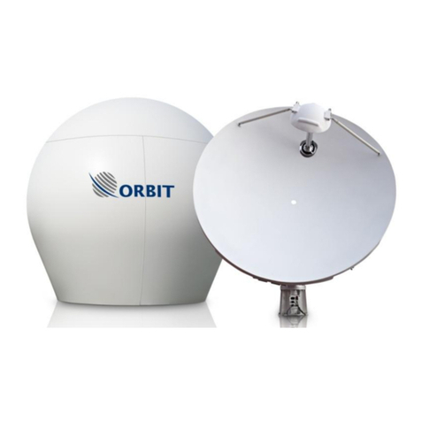
Orbit OceanTRx7 Specification sheet

COMMUNICATION WITHOUT BOUNDARIES
Orbit Communication Systems Ltd. P.O.B. 42504, Israel, Tel: +(972) 9 892 2777, Fax: +(972) 9 885 5944 www.orbit-cs.com
OceanTRx7TM
Maritime Stabilized VSAT System
Technical Note
OceanTrx CCU Installation and replacement
Document: TEC32-1664-014
Jan 2016

TEC32-1664-014_A OceanTRx™ CCU Technical Note ii
Copyright
© 2013 Orbit Communication Systems Ltd. All rights reserved.
All product names are trademarks of Orbit Communication Systems Ltd.
Other names are the property of the respective owners.
No part of this publication may be reproduced, transmitted, transcribed, stored in a
retrieval system, or translated into any language or computer language, in any form or
by any means, electronic or otherwise, without the prior written permission of Orbit
Communication Systems Ltd.
Disclaimer of Warranty
Orbit Communication Systems Ltd. has made every effort to ensure the accuracy and
relevancy of the material in this document. It is expected that all sections of this
document will be read thoroughly and that all information and procedures should be
fully understood.
However, Orbit Communication Systems Ltd. assumes no responsibility for any errors
that may appear in this document, and reserves the right to make changes to the
document without notice.
Orbit Communication Systems Ltd. makes no warranty of any kind in regard to this
document, including, but not limited to, the implied warranties of merchantability and
fitness for a particular purpose.
Orbit Communication Systems Ltd. disclaims any responsibility for incidental or
consequential damages in connection with the furnishing, performance or use of this
document.
Parts of this document may be based on hardware or software developed by
third-party vendors. Orbit Communication Systems Ltd. disclaims any responsibility for
the accuracy of this document with respect to such hardware and software, and
assumes no responsibility for incidental or consequential damages arising due to
discrepancies between this document and such hardware or software.

TEC32-1664-014_A OceanTRx™ CCU Technical Note iii
Revision History and Control
Revision History
Rev #
Modified by
Date
Comments
.
Albert
September 24, 2013
New Release
A
Albert/Tal.I
January 07 ,2016
Update according Changing CCU Software
and Part numbers

TEC32-1664-014_A OceanTRx™ CCU Technical Note iv
About this Manual
This manual is designed to guide you through the procedures required for maintaining the
CENTRAL CONTROL UNIT (CCU) for the OceanTRx7™ Maritime Satellite Communication
System.
Text Conventions
Style
Indicates
Example
Text
Normal descriptive text
Contents
Text
Words or figures that appear on the
screen or that should be typed
The name of a file or directory
System Status
<Text>
A key to be pressed
<ESC>
TEXT
The name of a hardware
component
ANTENNA
Text
The name of a GUI element
Operation Screen
The description of a procedure
To configure…
Notations
Indicates important information that should be noted.
Indicates a potential hazard.
Indicates the safest method of installation or an operation that must be adhered
to.

TEC32-1664-014_A OceanTRx™ CCU Technical Note v
Effective Releases
This document is effective for both OrBand™ and OceanTRx™ Maritime Satellite
Communication Systems.
For a description of the changes between OrBand™ and OceanTRx7™, refer to the
OceanTRx7™Maritime Satellite Communication System Release Notes
.

TEC32-1664-014_A OceanTRx™ CCU Technical Note vi
Table of Contents
1Introduction .....................................................................................................................1
1.1 Purpose....................................................................................................................1
1.2 CCU Description .....................................................................................................2
1.2.1 CCU Description .................................................................................................2
1.3 Spare Kit Contents ...................................................................................................4
1.4 Required Tools and Parts.........................................................................................4
2Preliminary Procedures ...................................................................................................5
3Replacing the CCU..........................................................................................................6
3.1 Removing the CCU ..................................................................................................6
3.2 Installing a CCU .......................................................................................................7
4SETUP............................................................................................................................8
4.1 Select CCU mode (working set) ...............................................................................8
4.2 Configuring the CCU IP and host communication IP address...................................9
4.3 Configuring the compass input. ..............................................................................10
4.4 Updating the system with General Software update module (GSU)........................11
5Perform Verification Test...............................................................................................13
6Appendices ...................................................................................................................14
6.1 Appendix A: Routing and Wiring.............................................................................14

TEC32-1664-014 OceanTRx7™ CCU Technical Note Page 1 of 15
1Introduction
1.1 Purpose
The purpose of this Technical Note is to provide detailed instructions on how to replace and
configure the CENTRAL CONTROL UNIT (CCU).
Figure 1-1: Central Control Unit

TEC32-1664-014 OceanTRx7™ CCU Technical Note Page 2 of 15
1.2 CCU Description
1.2.1 CCU Description
The CENTRAL CONTROL UNIT (CCU) is the interface between the system, the ship’s
equipment and the human operator.
The CCU provides the following functions:
Modem interface.
Conversion of compass readings.
Integrated Receiver/Decoder (IRD) interface.
Tx and Rx signal attenuation.
De-muxing and muxing of Tx and Rx signals, LAN and 10MHz reference signal.
Ethernet Hub
Running platform for MtsVLink software.
Transmission of system GPS data to the CFE modem.
SNMP support for network management.
The CCU is 1U high and is typically installed on a dedicated 19-inch rack in the ship’s radio
room.
There are two versions of the CCU supported by the system:
CCU –requires 10 MHz reference to be supplied by CFE modem And
Nmea-0183 Compass Only .
CCU WITH 10 MHZ –includes an internal 10 MHz reference source And
Synchro step by step ,Nmea-0183
The CCU requires external VGA display and keyboard with touchpad.
Orbit offers foldable 1U 17’ LCD drawer P/N: KIT32-1664-082-SP

TEC32-1664-014 OceanTRx7™ CCU Technical Note Page 3 of 15
The rear panel includes several connectors that connect to the ADE, the modem and the
ship’s gyrocompass (NMEA-0183, Synchro or Step-by-Step). An ATTENUATOR SWITCH
allows adaptation to various ADE-BDE cable lengths.
The CCU contains the BDMX module that connects to the ADMX via a single coaxial cable. The
BDMX provides integral amplification/attenuation of the Tx and Rx paths.
System operation is fully controlled from the CCU. Using the HMI, the operator can select the
desired satellite and channel from the CCU’s Satellite database. The system automatically
extracts the required data and deploys the ACU to acquire and track the selected satellite,
while compensating for the platform’s pitch, roll and yaw movements.
Figure 1-2: Front Panel Central Control Unit
Figure 1-3:Rear Panel Central Control Unit

TEC32-1664-014 OceanTRx7™ CCU Technical Note Page 4 of 15
1.3 Spare Kit Contents
The following table provides a list of the parts in the CCU spare kit.
Table 1-1: Spare Part Kit Contents (CCU regular)
KIT32-1664-031-SP
P/N
Description
Quantity
L00720008
CENTRAL CONTROL UNIT 1U W/O 10MHz&SYNCHRO
1
USB33-0823
MARINE USB LOAD WITH I/O MAN&DCD
1
Table 1-2: Spare Part Kit Contents (CCU with 10MHz source)
KIT32-1664-032-SP
P/N
Description
Quantity
L00720009
CENTRAL CONTROL.U W/10MHz&SYN
1
USB33-0823
MARINE USB LOAD WITH I/O MAN&DCD
1
1.4 Required Tools and Parts
The following table provides a list of tools and customer-supplied parts that are needed to
perform the procedures in this Technical Note.
Table 1-3: Required Tools and Parts
Tool/Part Name
Figure
Medium Phillips screwdriver
Small Flat screwdriver
Open wrench 13mm

TEC32-1664-014 OceanTRx7™ CCU Technical Note Page 5 of 15
2Preliminary Procedures
To Perform Preliminary Procedures:
The following preliminary procedure must be performed before replacing the CCU:
1. Turn off the satellite modem.
2. Take note of the CCU IP address and host communication IP address
3. Write down compass input and GPS output. I.e. COM port, baud rate, Format
Use caution wile handling the CCU connectors.
WARNING!
Use extra caution wile handling Syncro/SBS compass connector.
Danger high voltage exist even if the system power is switched off

TEC32-1664-014 OceanTRx7™ CCU Technical Note Page 6 of 15
3Replacing the CCU
3.1 Removing the CCU
Step 1
Turn off the CCU
Step 2
Disconnect all cables from the
CCU interfaces. Label each
cable as you disconnect it.
This will make installation of
the new unit easier.
Step 3
Use a screwdriver to remove
the screws securing the CCU to
the rack.
Support the CCU while
removing the bolts

TEC32-1664-014 OceanTRx7™ CCU Technical Note Page 7 of 15
3.2 Installing a CCU
Step 1
Install the CCU in a 19-inch
rack. It is recommended to
use the supplied rails to
install the CCU in the rack.
Step 2
Connect all the cables that
were disconnected from the
old CCU. Ensure that each
cable is connected to the
appropriate connector.

TEC32-1664-014 OceanTRx7™ CCU Technical Note Page 8 of 15
4SETUP
This chapter describes the following procedures:
Select CCU mode (working set)
Configuring the CCU IP and host communication IP address
Configuring the compass input
Updating the system with General Software update module (GSU)
4.1 Select CCU mode (working set)
1. On the Windows 7 Embedded right click on the CCU manager.
2. Select working sets. List of available CCU modes will show
3. Select the relevant working set according the system type
4. Press Set &reboot. The system will issue confirmation prompt

TEC32-1664-014 OceanTRx7™ CCU Technical Note Page 9 of 15
4.2 Configuring the CCU IP and host communication IP
address
1. Power on the CCU. Verify normal boot sequence
2. Launch the MTSDOCK application (start programs)
3. Access remote CCU connect 192.9.200.22
4. GoRemote CCU edit network parameters
5. Enter the new CCU IP address.
6. Configure the required network parameters and click OK.
7. Select the RemoteCCU menu (again) and click Reboot. The CCU will reboot
8. In the MTSDOCK application open the ACU menu and select Edit Network Parameters
chose Detect ACU. The Detected ACU dialog box opens.
Figure 4-1: Detected ACU Dialog Box
9. The ACU IP address and subnet mask appears. Take note of it.
10. Switch to the MTSVLINK application. On the Host menu select Communication.

TEC32-1664-014 OceanTRx7™ CCU Technical Note Page 10 of 15
11. Enter the ACU IP address obtained during the preliminary procedure
For Dual or Triple System topology, the above procedure should be repeated for
each antenna MTSVLINK instance
4.3 Configuring the compass input.
To configure the compass input:
1. Open MTSVLINK application
2. Open the Host menu and select Host Hardware Interface.
3. [general] tab enable set to yes
4. [Compass input] tab. Enable set yes. For NMEA only configure the parameters
according values retrieved during preliminary procedure.
5. Verify the reading value is displaying the ship heading
6. [GPS output] tab (optional). Enable set yes. Configure the parameters according
values retrieved during preliminary procedure.
If the parameters of the Compass and GPS output are not available during the preliminary
procedure contact the ship electrician /air time provider (NOC) to obtain it.

TEC32-1664-014 OceanTRx7™ CCU Technical Note Page 11 of 15
4.4 Updating the system with General Software update module
(GSU)
1. Obtain the latest software package GSU (
GSUpdate.zip
) from Orbit’s support team.
2. Copy the files to a USB flash drive. Connect it to the USB port in the CCU front panel.
4. Launch the MTSDOCK utility from startprograms
5. Select ThisHost menu and chose General Software Update.
6. The Select ZIP Archive with Software Updates dialog box appears.
Figure 4-2: Select ZIP Archive with Software Updates Dialog Box
7. Select the GSU file from the USB Flash drive.
8. Click Open (Enter). New dialog box will pop up ask to enter the ACU and the CCU IP
address, Enter the address previous found.
Figure 4-3: Connect ACU, CCU Message Box

TEC32-1664-014 OceanTRx7™ CCU Technical Note Page 12 of 15
9. Click Open (Enter). The automated upgrade process will start. It will update the ACU
(VSATWORKS) executable, CCUsMTSVLINK and also the Servo Drives FIRMWARE
10. Reboot prompt will be issued at end of the process. Reboot by pressing OK.
11. When communication is reestablished between the ACU and the CCU,
12. Click the Version command on the MTSLINK Menu Bar and verify that the new version
was successfully installed and matches the software version used by the ACU
.
Figure 4-5: Version Message Box

TEC32-1664-014 OceanTRx7™ CCU Technical Note Page 13 of 15
5Perform Verification Test
To Perform Verification Test:
1. Power up the CCU/DSS (see the
OceanTRx7™ Installation and Operation
Manual
for instructions).
2. Verify that there is communication between the ACU and CCU and there are no
ERR/WRN system messages.
3. Verify heading is available.
4. Make sure compatible modems receive GPS from the system
5. Verify Modem Rx EdNo and TX power within limits, using NOC assistance

TEC32-1664-014 OceanTRx7™ CCU Technical Note Page 14 of 15
6Appendix
6.1 Appendix A: Routing and Wiring
Basic connections
To Connect the ADE-BDE LMR Coaxial Cable to the CCU:
1. Connect the 3P power cable to the CCU power plug.
2. Connect Grounding to the unit
2. Connect the cable coming from the antenna to the ADE connector on the CCU.
Modem Tx and Rx Connection
To Connect the Modem Tx and Rx Ports to a CCU without 10MHz:
1. Connect a cable from the modem’s Rx port to the RX connector on the CCU.
2. Connect a cable from the modem’s Tx port to the TX connector on the CCU. The modem
supplies the 10MHz reference signal with the Tx signal.
The following figure shows the connections.
Figure 6-1: CCU without 10 MHz Tx/Rx Modem Connections
Other manuals for OceanTRx7
3
Table of contents
Other Orbit Marine Equipment manuals
Popular Marine Equipment manuals by other brands

Syqwest
Syqwest Bathy 2010P Operation and maintenance manual

EMS
EMS FireCell FC-179-002 installation guide

Boss Audio Systems
Boss Audio Systems MR637U Manual de usuario

Raymarine
Raymarine SmartPilot X-5 Sport Installation & setup guide

Teletek electronics
Teletek electronics SensoIRIS WSST IS Installation instruction

JRC
JRC JUE-95SA - Operation guide