First Aid Method
v
7. When to stop cardiopulmonary resuscitation (CPR)
a) When the injured or ill person has been handed over to the
emergency services
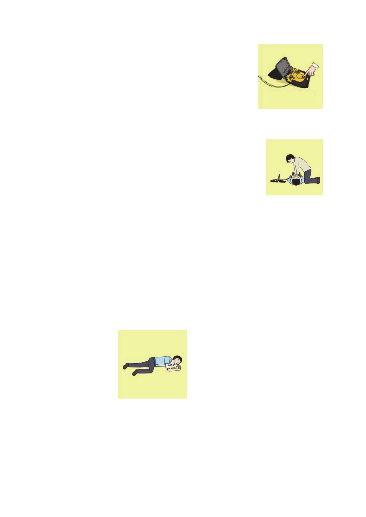
b) When the injured or ill person has started moaning or breathing
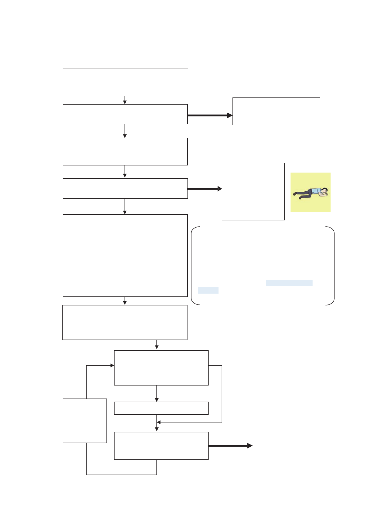
normally, lay on the side in a recovery position and wait for the
arrival of emergency services.
8. Arrival and preparation of an AED
a) Place the AED at an easy-to-use position.
If there are multiple first-aiders, continue
CPR until the AED becomes ready.
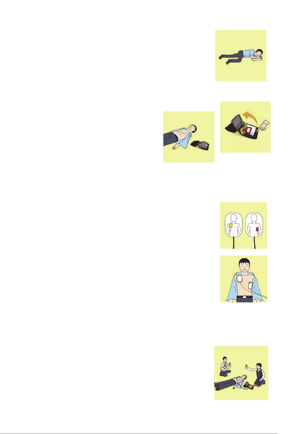
b) Turn on the power to the AED unit.
Depending on the model of the AED, you
may have to push the power on button, or
the AED automatically turns on when you
open the cover.
c) Follow the voice prompts of the AED.
9. Attach the electrode pads to the injured or ill person's bare chest
a) Remove all clothing from the chest, abdomen, and arms.
b) Open the package of electrode pads, peel the pads off and securely
place them on the chest of the injured or ill person, with the adhesive
side facing the chest. If the pads are not securely attached to the chest,
the AED may not function. Paste the pads exactly at the positions
indicated on the pads, If the chest is wet with water, wipe dry with a dry
towel and the like, and then paste the pads. If there is a pacemaker or
implantable cardioverter defibrillator (ICD), paste the pads at least 3
cm away from them. If a medical patch or plaster is present, peel it off and
then paste the pads. If the injured or ill person's chest hair is thick,
paste the pads on the chest hair once, peel them off to remove the
chest hair, and then paste new pads.
c) Some AED models require to connect a connector by following voice prompts.
d) The electrode pads for small children should not be used for children over the age of 8 and for
adults.
10. Electrocardiogram analysis
a) The AED automatically analyzes electrocardiograms. Follow the
voice prompts of the AED and ensure that nobody is touching the
injured or ill person while you are operating the AED.
b) On some AED models, you may need to push a button to analyze
the heart rhythm.
Turn on the power.