Exalto type 223BS - 7
2. Technical data
2.1 General
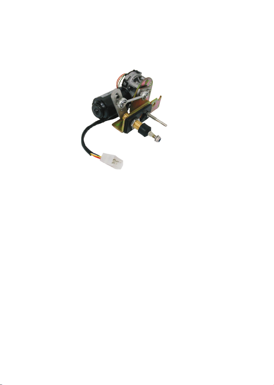
• Product Exalto windscreen wiper
• Type 223BS (Bulkhead tting, Slot adjustable, Open housing)
• Catalogue numbers XA2167.30/35 -/32 -/40 -/45 -/50 (12V)
XA2168.30/35 -/32 -/40 -/45 -/50 (24V)
2.2 Electrical data 12 Volt
• Torque (max.) 23 Nm
• Voltage 12 Volt
• Current 3A
• Power consumption (max.) 36 W
• Number of revolutions Low speed 38 rpm, high speed 59rpm
• Recommended cable 5 wires, 1½ mm² (16 g) or 2½ mm² (14 g) up to 10 m
long
• Recommended fuse 6 A slow blow
• Grounding Insulated earth return
2.2 Electrical data 24 Volt
• Torque (max.) 25 Nm
• Voltage 24 Volt
• Current 1.5 A
• Power consumption (max.) 36 W
• Number of revolutions Low speed 35rpm, high speed 56 rpm
• Recommended cable 5 wires, 1½ mm² (16 g) or 2½ mm² (14 g) up to 10 m
long
• Recommended fuse 4 A slow blow
• Grounding Insulated earth return
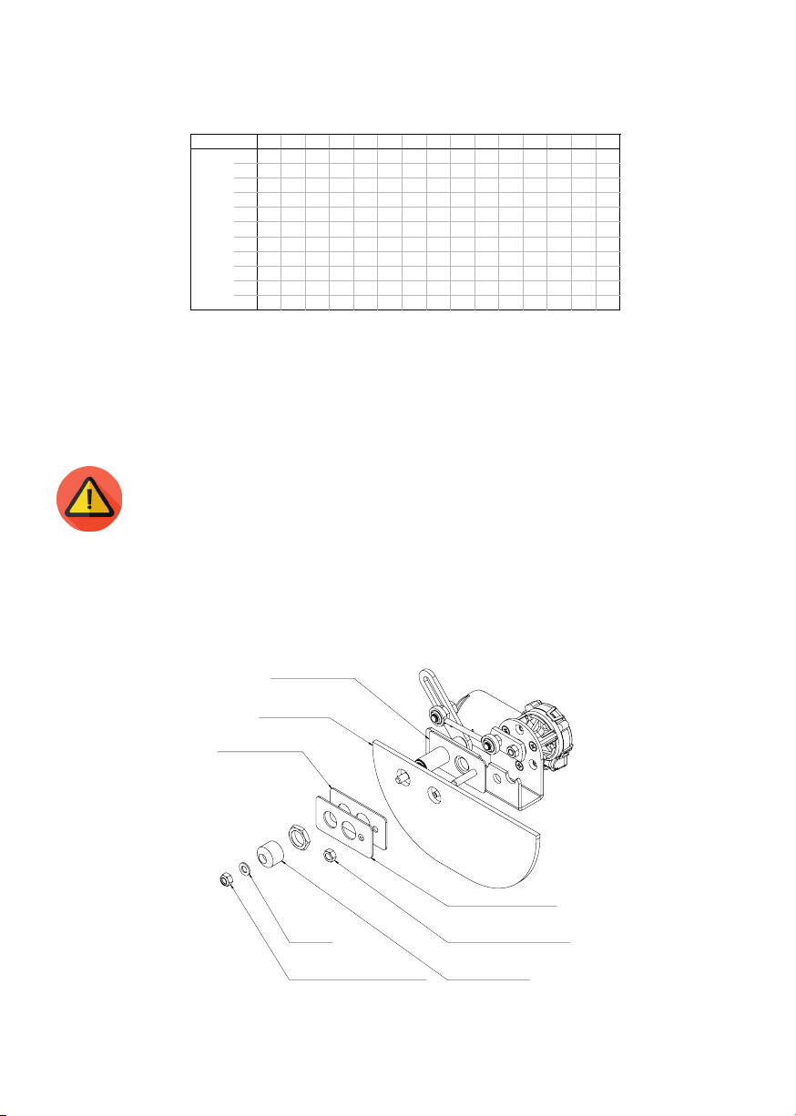
2.3 Mechanical data
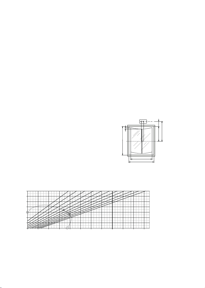
• Dimensions L x w x h = 173 x 107 x 131 mm
• Shaft diameters Drive shaft Ø 20 / support shaft Ø 8 mm at 50 mm ctrs
• Mounting In bulkhead (20mm up to 125 mm)
• Bearing Bronze housing, self-lubricating
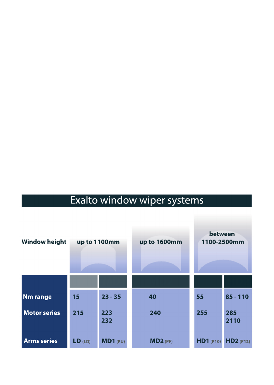
• Wiper arms Model MD1 (PU) up to 750 mm
• Wiper blades Up to 750 mm
• Wipe arc Wipe arc 40°-90°, adjustable (step-less)
• Weight Approx. 2,30 kg