Thales MissionLINK Certus 350 User manual

i
Installation Guide 84465 Rev. H
Installation Guide 84465 Rev. H
MissionLINK®
Installation Guide for Certus 350 and Certus 200
This document contains technology controlled for export by the U.S. Department of Commerce in
accordance with Export Administration Regulations. Diversion contrary to U.S. law prohibited.
MAY 2022
JUNE 2017
JUNE 2017
JUNE 2017
COPYRIGHT © 2022
THALES DEFENSE & SECURITY, INC.
ALL RIGHTS RESERVED
ii
Installation Guide 84465 Rev. H
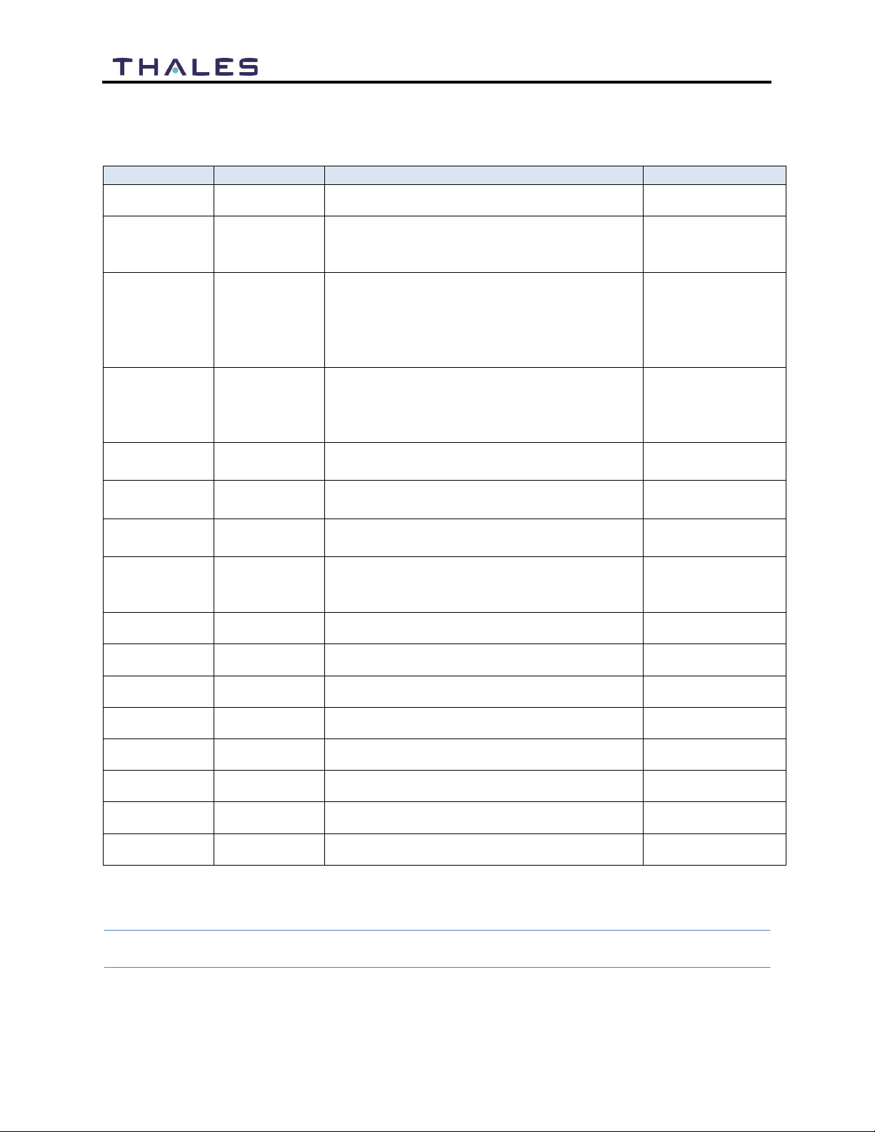
RECORD OF CHANGES
Rev
Date
Description of Change
Author
Rev A
June 2018
Initial Release
SJacques
Rev B
Sept 2018
ECN: 42141
Update based on Beta user feedback
and Testing
SJacques
Rev C
Jan 2020
ECN 43088
Added 700 kbps
Updated accessory list
Added Antenna dimensions and hole
pattern
SJacques
Rev D
Oct 2020
ECN: 53617
Updated based on new software release
2.2
Updated equipment PNs
SJacques
Rev E
Feb 2021
ECN: 53837
Updated to include Certus 200
SJacques
Rev F
May 2021
ECN:54065
Updated Industry Canada Cert
SJacques
Rev G
Dec 2021
ECN: 54408
Added Certus 200 Mounting
SPeters
Rev H
ECN 54668
Adds Brazil, Mexico, Korea and Japan
Certs and updated pictures
SPeters
WARNING –INFORMATION SUBJECT TO EXPORT CONTROL RESTRICTIONS
This document contains technology controlled for export by the U.S. Department of
Commerce in accordance with Export Administration Regulations (EAR). Diversion contrary
to U.S. law prohibited. Include this notice with any reproduced portion of this document.

iii
Installation Guide 84465 Rev. H
Export Compliance:
This product is controlled by the export laws and regulations of the United States of America. The U.S. Government may restrict the
export or re-export of this product to certain individuals and/or destinations. For further information, contact the U.S. Department of
Commerce, Bureau of Industry and Security.
This product User shall comply with all applicable laws related to export and import of this product in any jurisdiction and/or
government authority. User shall be responsible for complying with any and all export and import restrictions, laws and regulations in
any country User is conducting business.
Disclaimer:
This manual contains information that is current as of the date shown on the front cover. Every effort has been made to ensure the
correctness and completeness of the material in this document. The information in this document is subject to change without notice.
Thales®, Thales MissionLINK®, and any other Thales trademark or Thales service mark referred to or displayed in this document are
trademarks or registered trademarks of Thales.
Legal Notices
This product is subject to a Limited Warranty, Limitations, Exclusions, and Terms and Conditions, which can be found on line at
www.thalesdsi.com.
Prior to Installing this product, read and understand this Installation Guide and the User Manual, including the safety warnings and
information. Failure to do so could result in serious injury or death.
Intellectual Property
User acknowledges that the Products
involve
valuable patent, copyright, trademark, trade secret and other proprietary rights
of
Thales and others. No title to or ownership of any proprietary rights related to any Product is transferred to User or any Customer
pursuant to the use of this product. The purchase of any Thales products shall not be deemed to grant either directly or by implication
or otherwise, any license under copyrights, patents, or patent applications of Thales or any third party software providers, except for
the normal, nonexclusive, royalty free license to use that arises by operation of law in the sale of a product.
Content C opy rig ht
User is exclusively responsible for the use of this product, including proper use of third party copyrighted materials. If the User violates
these terms, the User agrees to defend, indemnify and hold Thales harmless with respect to any claims or actions by third parties
related to the improper use of copyrighted material and to pay all costs, damages, fines and other amounts incurred by Thales, or on
its behalf, in the defense of any such claims or actions.
Indemnity
User agrees to defend, indemnify and hold Thales harmless with respect to any claims or actions by any governmental entities or other
third parties related to any violation of law with use of the Product or Accessories, misuse of the Product or Accessories under these
Terms and Conditions, or any other violation of these Terms and Conditions and further agrees to pay all costs, damages, fines and
other amounts incurred by Thales, or on Thales’s behalf, in the defense of any such claims or actions.
SOF TWARE LICENSE
The following terms govern User’s access and use of the Thales-supplied software (“Software”) contained on the Product or
Accessories.
License. Conditioned upon compliance with these Terms and Conditions, Thales grants to USER a nonexclusive and nontransferable
license to use for USER’s internal purposes the Software and the Documentation. “Documentation” means any written information
pertaining to the Software and made available by Thales with the Software in any manner. USER shall use the Software solely as
embedded for operation of this product.
No other licenses are granted by implication, estoppel or otherwise.
Thales Pro duc t War ran ty Claim P roc ess
Please see the Thales website at www.thalesdsi.com.
User Documentation:
Thales Defense & Security, Inc. continually evaluates its user documentation for accuracy and completeness. Any suggestions you may
have for changes or additions should be sent to THALES_ILS@thalesdsi.com Subject Line: Thales MissionLINK® Installation Guide (PN
84465/84465-IETM).
iv
Installation Guide 84465 Rev. H
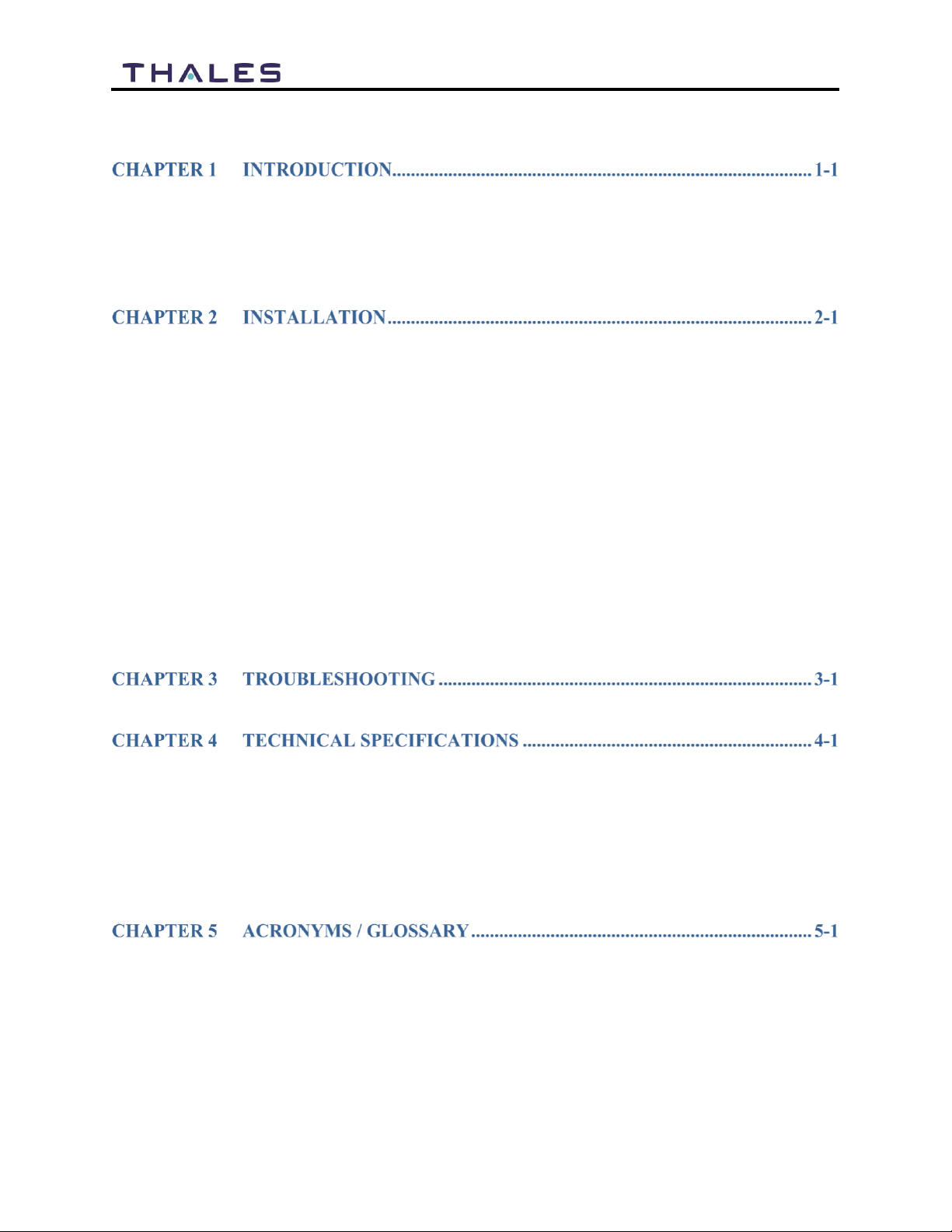
Table of Contents
INTRODUCTION .........................................................................................................................1-1
EQUIPMENT OVERVIEW ............................................................................................................1-1
Terminal Unit (TU)..............................................................................................................1-2
Broadband Active Antenna (BAA).......................................................................................1-5
MISSIONLINK KIT CONTENTS AND ACCESSORIES ...................................................................1-6
GENERAL GUIDELINES..............................................................................................................2-1
TOOLS AND SUPPLIES NEEDED FOR INSTALLATION...................................................................2-1
Preparation..........................................................................................................................2-1
Precautions During Installation..........................................................................................2-2
INSTALLATION ..........................................................................................................................2-2
INSTALLATION OF THE CERTUS 350 BROADBAND ACTIVE ANTENNA (BAA)........................2-3
Certus 350 Antenna Dimensions and Hole Pattern.............................................................2-4
Magnetic Mounting Detail...................................................................................................2-5
Hard Mounting Detail..........................................................................................................2-7
INSTALLATION OF THE CERTUS 200 BROADBAND ACTIVE ANTENNA (BAA)........................2-9
Certus 200 Antenna Dimensions and Hole Pattern...........................................................2-11
INSTALLING THE TU ...............................................................................................................2-12
CONNECTING POWER TO THE TU............................................................................................2-15
DC Power Connection.......................................................................................................2-16
SYSTEM STATUS INDICATORS .................................................................................................2-18
TROUBLESHOOTING ..................................................................................................................3-1
TECHNICAL SPECIFICATIONS.....................................................................................................4-1
TEMPERATURE..........................................................................................................................4-2
PHYSICAL CHARACTERISTICS ...................................................................................................4-2
CONNECTOR DETAILS...............................................................................................................4-3
General Purpose Inputs / Outputs (GPIO)..........................................................................4-3
TU 12V Connection Detail...................................................................................................4-4
TU 10-32VDC Connection Detail........................................................................................4-4
ACRONYMS /GLOSSARY...........................................................................................................5-1
INDEX.............................................................................................................................INDEX-1
APPENDIX ACERTUS 350 ANTENNA MOUNTING TEMPLATE (PN 3900013-1).........................A-1
APPENDIX BTERMINAL UNIT MOUNTING TEMPLATE (PN 3900011-1) ................................... B-1

v
Installation Guide 84465 Rev. H
List of Figures
FIGURE 1-1 MISSIONLINK SYSTEM WITH CONNECTED HARDWARE ............................................1-1
FIGURE 1-2 TERMINAL UNIT (TU)................................................................................................1-2
FIGURE 1-3 TERMINAL UNIT (TU) LEDS......................................................................................1-3
FIGURE 1-4 TERMINAL UNIT (TU) FRONT PANEL DETAIL ............................................................1-4
FIGURE 1-5 TERMINAL UNIT (TU) BACK PANEL DETAIL..............................................................1-5
FIGURE 1-6 BROADBAND ACTIVE ANTENNA (BAA) FOR CERTUS 350 &CERTUS 200 SYSTEMS..1-5
FIGURE 2-1 ANTENNA DIMENSION AND HOLE PATTERN...............................................................2-4
FIGURE 2-2 MAGNETIC MOUNT ANTENNA ...................................................................................2-5
FIGURE 2-3 HARD MOUNT ANTENNA ...........................................................................................2-7
FIGURE 2-4 CERTUS 200 PREMIUM L-BRACKET POLE MOUNT (1100855-503).............................2-10
FIGURE 4-1 GPIO CONNECTOR PIN DETAIL .................................................................................4-3
FIGURE 4-2 12V INPUT AND MATING CONNECTOR DETAIL..........................................................4-4
FIGURE 4-3 10-32 VDC AND MATING CONNECTOR DETAIL.........................................................4-4
List of Tables
TABLE 1-1 TERMINAL UNIT LED STATUS ....................................................................................1-3
TABLE 1-2 STANDARD KIT,MISSIONLINK CERTUS 350, LIST OF EQUIPMENT.............................1-6
TABLE 1-3 BASE KIT,MISSIONLINK CERTUS 350, LIST OF EQUIPMENT......................................1-7
TABLE 1-4 BASE KIT,MISSIONLINK CERTUS 200, LIST OF EQUIPMENT......................................1-7
TABLE 1-5 AVAILABLE MISSIONLINK ACCESSORIES...................................................................1-8
TABLE 2-1 MAGNETIC MOUNT KIT COMPONENTS (PN 1100790-501).........................................2-5
TABLE 2-2 INSTALLATION KIT,MOUNTING HARDWARE (LAND)(PN 1100792-501)...................2-7
TABLE 3-1 TROUBLESHOOTING.....................................................................................................3-1
TABLE 4-1 TECHNICAL SPECIFICATIONS .......................................................................................4-1
TABLE 4-2 OPERATING AND STORAGE TEMPERATURES................................................................4-2
TABLE 4-3 PHYSICAL CHARACTERISTICS......................................................................................4-2
TABLE 4-4 GPIO CONNECTOR PIN DEFINITION ............................................................................4-3
TABLE 5-1 LIST OF ACRONYMS.....................................................................................................5-1
TABLE 5-2 LIST OF DEFINITIONS...................................................................................................5-2
vi
Installation Guide 84465 Rev. H
Installation Guide 84465 Rev. H
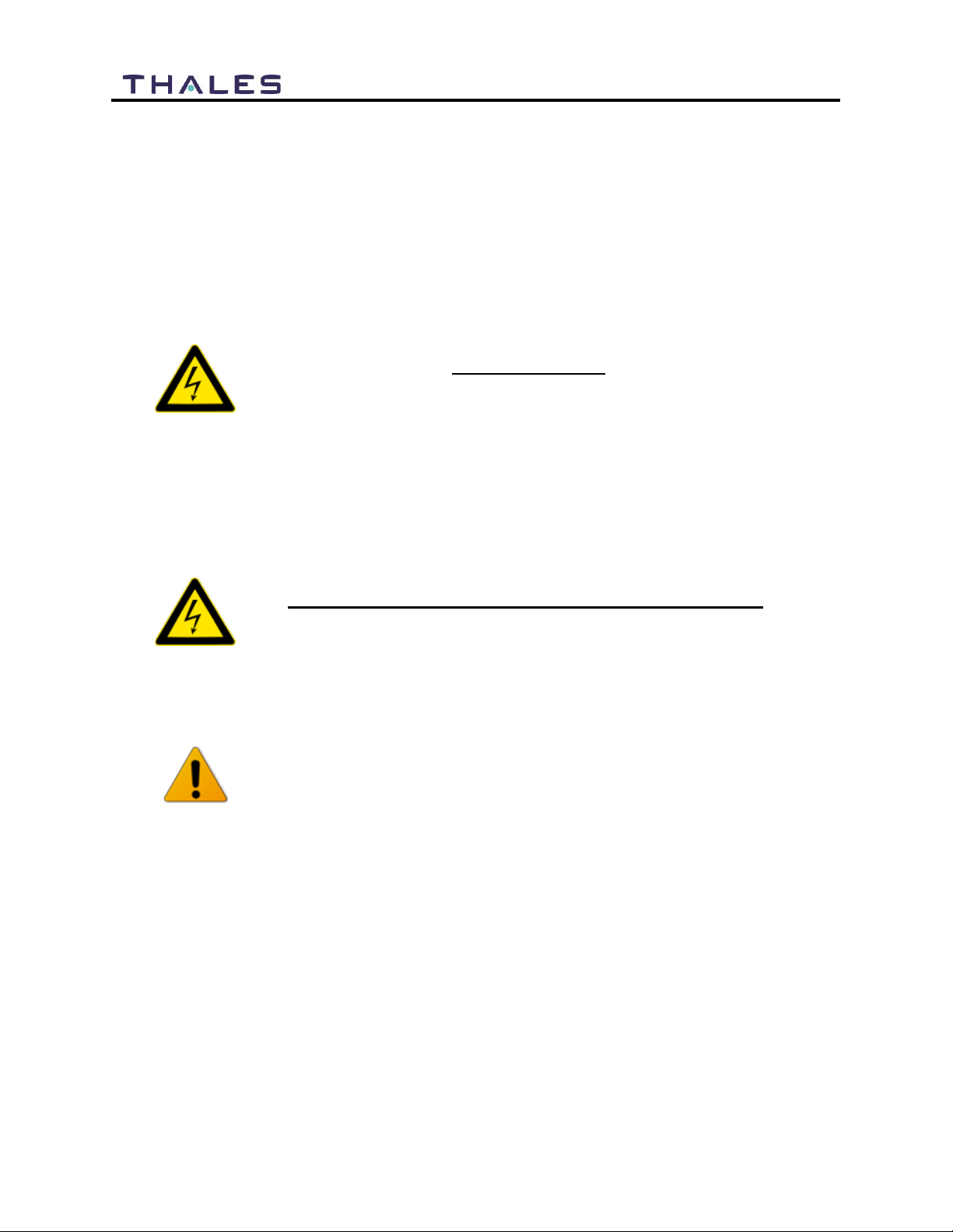
SAFETY
The Thales MissionLINK®system should only be installed by a qualified installer of land
electronic systems. Improper installation could lead to system failure or could result in injury.
The following are general safety precautions and warnings that all personnel must read and
understand prior to installation, operation and maintenance of the MissionLINK system. Each
chapter may have other specific warnings and cautions.
WARNING
USHOCK HAZARD
The MissionLINK system is a sealed system andis not meant to be opened
for repair in the field by operators or technicians. Covers must remain in
place at all times on the Terminal Unit (TU) and Broadband Active
Antenna (BAA) to maintain the warranty terms. Make sure the system is
correctly grounded and power is off when installing, configuring and
connecting components.
WARNING
DO NOT OPERATE IN AN EXPLOSIVE ATMOSPHERE
This equipment is not designed to be operated in explosive environments
or in the presence of combustible fumes. Operating this or any electrical
equipment in such an environment represents an extreme safety hazard.
CAUTION
LITHIUM ION BATTERIES
The TU contains a small Li-ion battery. Li-ion batteries have a very high
energy density. Exercise precaution when handling and testing. Do not
short circuit, overcharge, crush, mutilate, nail penetrate, apply reverse
polarity, expose to high temperature or disassemble. High case
temperature resulting from abuse of the cell could cause physical injury.
vii
Installation Guide 84465 Rev. H
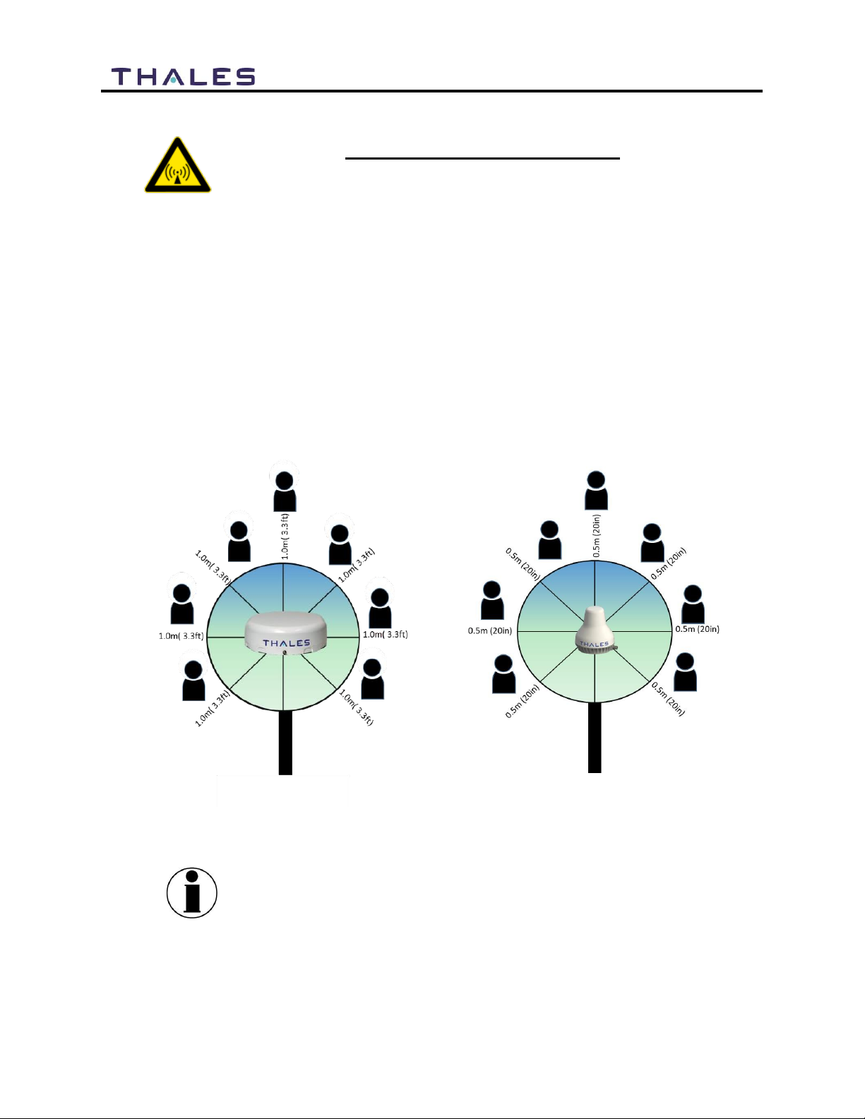
WARNING
ANTENNA RADIATION HAZARDS
To comply with FCC Radio Frequency radiation exposure limits, the
antenna must be installed at a minimum safe distance as shown below.
During operation, the antenna radiates high power at microwave
frequencies that can be harmful to individuals. While the unit is
operating, personnel should maintain a safe from the antenna. The
antenna should be mounted in an area that prevents the possibility of
close exposure to the antenna’s radiation.
For the Certus 350 antenna, please remain at least 1.0m (3.3 feet) from
the antenna while in operation.
For the Certus 200 antenna, please remain at least 0.5m (20 inches)
from the antenna while in operation.
Certus 350 Certus 200
NOTE
Este Equipamento não tem direito à proteção contra interferencia
prejudicial e não pode causar interferência em Sistemas
devidamente autorizados
viii
Installation Guide 84465 Rev. H
FCC Information
NOTE
Certus 350
FCC Identifier: OKCMF350BV
Contains FCC ID: OKCWROOM32U
NOTE
Certus 200
FCC Identifier: OKCMF200BV
Contains FCC ID: OKCWROOM32U
Changes or modifications not expressly approved by the manufacturer could void the user’s
authority to operate the equipment.
Note:
This equipment has been tested and found to comply with the limits for a Class B digital device,
pursuant to part 15 of the FCC Rules. These limits are designed to provide reasonable protection
against harmful interference in a residential installation. This equipment generates, uses and can
radiate radio frequency energy and, if not installed and used in accordance with the instructions,
may cause harmful interference to radio communications. However, there is no guarantee that
interference will not occur in a particular installation. If this equipment does cause harmful
interference to radio or television reception, which can be determined by turning the equipment
off and on, the user is encouraged to try to correct the interference by one or more of the
following measures:
Reorient or relocate the receiving antenna.
Increase the separation between the equipment and receiver.
Connect the equipment to a source on a circuit different from that to which the receiver is
connected.
Consult the dealer or an experienced radio/TV technician for help.
ix
Installation Guide 84465 Rev. H
Industry Canada Information
NOTE
Certus 350
Industry Canada: 473C-MF350BV
Contains IC: 473C-WROOM32U
NOTE
Certus 200
Industry Canada: 473C-MF200BV
Contains IC: 473C-WROOM32U
Under Industry Canada regulations, this radio transmitter may only operate using an antenna of a
type and maximum (or lesser) gain approved for the transmitter by Industry Canada. To reduce
potential radio interference to other users, the antenna type and its gain should be so chosen that
the equivalent isotropically radiated power (e.i.r.p.) is not more than that necessary for successful
communication.
Conformément à la réglementation d'Industrie Canada, le présent émetteur radio peut
fonctionner avec une antenne d'un type et d'un gain maximal (ou inférieur) approuvé pour
l'émetteur par Industrie Canada. Dans le but de réduire les risques de brouillage radioélectrique
à l'intention des autres utilisateurs, il faut choisir le type d'antenne et son gain de sorte que la
puissance isotrope rayonnée équivalente (p.i.r.e.) ne dépasse pas l'intensité nécessaire à
l'établissement d'une communication satisfaisante.
This radio transmitter (473C-MF350BV or 473C-MF200BV) has been approved by Industry
Canada to operate with the antenna listed in Table 4-1 with the maximum permissible gain and
required antenna impedance for each antenna type indicated. Antenna types not included in this
list, having a gain greater than the maximum gain indicated for that type, are strictly prohibited for
use with this device.
Le présent émetteur radio (473C-VF350BM ou 473C-MF200BV) a été approuvé par Industrie
Canada pour fonctionner avec les types d'antenne énumérés ci-dessous et ayant un gain
admissible maximal et l'impédance requise pour chaque type d'antenne. Les types d'antenne non
inclus dans cette liste, ou dont le gain est supérieur au gain maximal indiqué, sont strictement
interdits pour l'exploitation de l'émetteur
This device complies with Industry Canada license-exempt RSS standard(s). Operation is subject
to the following two conditions: (1) this device may not cause interference, and (2) this device
must accept any interference, including interference that may cause undesired operation of the
device.
Le présent appareil est conforme aux CNR d'Industrie Canada applicables aux appareils radio
exempts de licence. L'exploitation est autorisée aux deux conditions suivantes : (1) l'appareil ne
doit pas produire de brouillage, et (2) l'utilisateur de l'appareil doit accepter tout brouillage
radioélectrique subi, même si le brouillage est susceptible d'en compromettre le fonctionnement.

x
Installation Guide 84465 Rev. H
xi
Installation Guide 84465 Rev. H

xii
Installation Guide 84465 Rev. H
THALES DEFENSE & SECURITY, INC.
Declaration of Conformity with Radio Equipment Directive
The undersigned of this letter declares that the following equipment complies with the
specifications of Radio Equipment Directive (2014/53/EU) concerning Radio &
Telecommunications Equipment.
Equipment included in thisdeclaration
VF350BM Certus 350 VesseLINK Broadband Maritime Satellite Terminal and Antenna
VF200BM Certus 200 VesseLINK Broadband Maritime Satellite Terminal and Antenna
MF350BV Certus 350 MissionLINK Broadband Maritime Satellite Terminal and Antenna
MF200BV Certus 200 MissionLINK Broadband Maritime Satellite Terminal and Antenna
Equipment Applicability
The VesseLINK and MissionLINK provide voice and high speed data communication over
100% of the globe through the Iridium Certus broadband Satellite system.
Declaration
The health requirement is met by conforming to EU standard EN62311. . The safety
requirement is met by conforming to EN 60950-1:2006 w/A2:2013 (for Certus 350) and to
EN62368-1:2014 (for Certus 200). The electromagnetic compatibility asset out in Directive
2014/30/EU is met byconforming to the EU standards ETSI EN 301-489-1and ETSI EN
301-489-17. Effective andefficient use of radio spectrum in orderto avoid harmful
interference is met by conforming to the ETSI EN301-441standard.
Manufacturer
ThalesDefense & Security, Inc. 22605 Gateway Center Drive
Clarksburg, Maryland 20871 U.S.A.
Place and Date
Clarksburg, MD, 14 January 2021
Scott Peters
Director, Program Management

xiii
Installation Guide 84465 Rev. H

xiv
Installation Guide 84465 Rev. H
xv
Installation Guide 84465 Rev. H
xvi
Installation Guide 84465 Rev. H
xvii
Installation Guide 84465 Rev. H
1-1
Installation Guide 84465 Rev. H
INTRODUCTION
Introduction
This installation guide provides an overview of the MissionLINK equipment and instructions for
proper installation and initial start-up of the Certus 350 and Certus 200 MissionLINK systems. It
contains critical information and safety guidelines for those who install the system and perform
initial system activation and test.
After initial start-up, for more detailed operational procedures, refer to the MissionLINK User
Manual (Document # 84468) located on the Thales website and also accessible through the
terminal’s Management Portal.
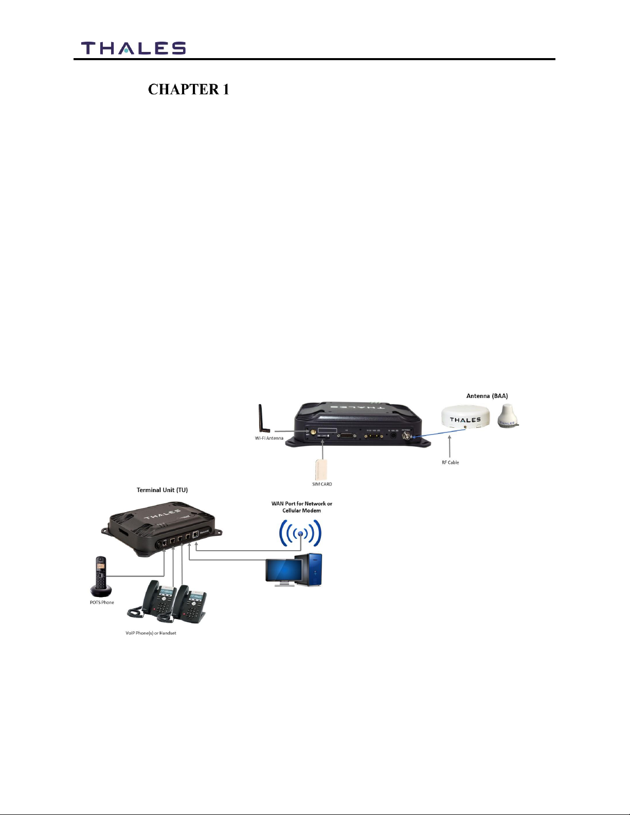
A typical MissionLINK user setup that includes standard kit items, accessories and user provided
items such as a POTS phone, VoIP phones and a computer is shown in Figure 1-1. A cellular
modem or other network modem can be connected to the WAN port for data least-cost routing
operations. Voice calls are always routed through the Iridium satellite system and not the WAN
port. Refer to Table 1-2, Table 1-3, Table 1-4 and Table 1-5 for a list of kit contents, available
accessories and spare parts.
Equipment Overview
Figure 1-1 MissionLINK System with Connected Hardware
1-2
Installation Guide 84465 Rev. H
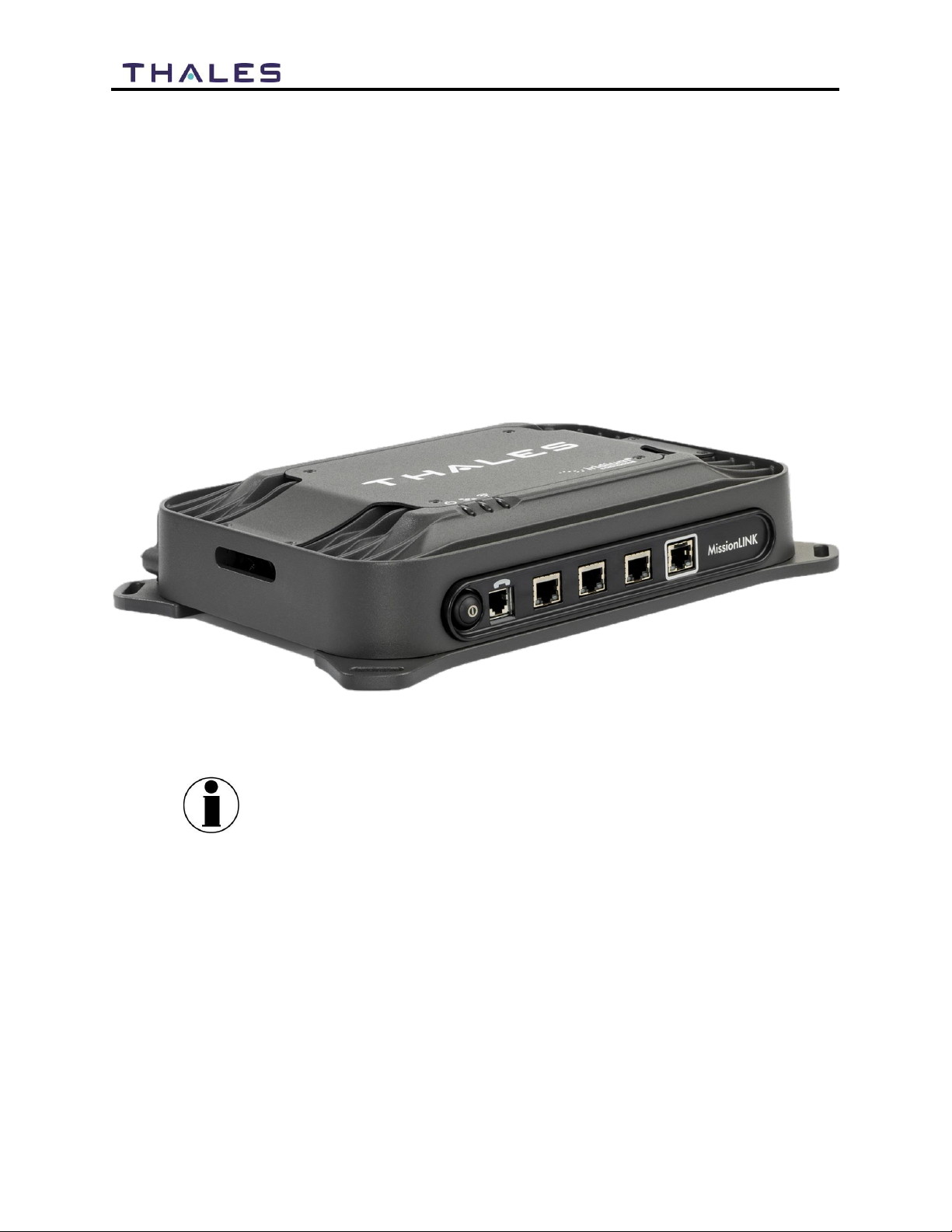
Terminal Unit (TU)
The Terminal Unit (TU) supports voice and data communications in a land mobile or terrestrial
fixed environment. The TU is capable of supporting wireless voice and data that links the user
with the Iridium satellite network. The TU, depending on Line of Site (LOS) and Low Earth
Orbiting (LEO) Satellites, will be able to maintain satellite connectivity while experiencing
conditions varying from urban canyons to high vibration from road movement. As a wireless
access point, the TU provides Wi-Fi (802.11) access for data and Voice over IP (VoIP) calls.
Three RJ-45 Ethernet connectors and one RJ14 connector enables the user to tether directly to
the TU, if desired. The Management Portal is a graphical user interface that can be used to
modify system settings and indicate system status. The TU is powered by either a DC power
cable with a 10-32V input range and remote start wire or an AC/DC power supply,
accommodating all types of vehicles, applications and power sources.
Figure 1-2 Terminal Unit (TU)
NOTE
Wi-Fi Access Point:
The internal Wi-Fi access point is not a high capacity Wi-Fi system.
If heavy simultaneous data usage is expected through Wi-Fi, it may
be best to use an external commercial Wi-Fi router connected to the
BDU’s LAN port.
1-3
Installation Guide 84465 Rev. H
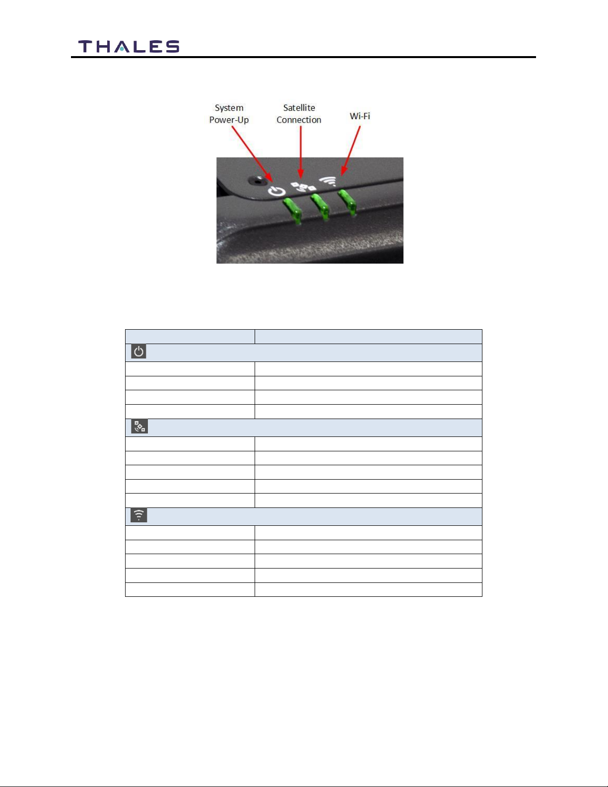
The TU has three status LEDs on the top of the unit that indicate status of system power-up,
satellite connection and the Wi-Fi.
Figure 1-3 Terminal Unit (TU) LEDs
Table 1-1 Terminal Unit LED Status
Indicator
Description
BSystem
Solid GREEN
System functioning properly
Flashing GREEN
System busy (Booting up)
Solid RED
Fault (minor issue)
Flashing RED
Critical fault (major issue)
BSatellite
Solid BLUE
Connected and passing data (over satellite)
Solid GREEN
System functioning properly
Flashing GREEN
Acquiring satellite
Solid RED
Fault (minor issue)
Flashing RED
Critical fault (major issue)
Wi-Fi
OFF
Wi-Fi OFF
Flashing GREEN
Wi-Fi busy
Solid Green
System functioning properly
Solid RED
Fault (minor issue)
Flashing RED
Critical fault (major issue)
This manual suits for next models
1
Table of contents
Other Thales Marine Equipment manuals


