OREX PcCR 1417 User manual

PcCR 1417ACL4 System
Automatic Cassette Loading
Version
User Manual
To be used with OREX Scanner Interface Version 2.5.1.0.9

OREX Ltd. is a market innovator in the field of portable Computed Radiography
Technologies—designed and priced for low-volume clinic or field unit needs.
Founded in 1995 under the name of Digident, the company initially entered the market of
desktop dental radiography providing high quality, portable CR reading units for dental and
orthodontic professionals around the world. The secret of Digident/OREX’s rapid success lies
in the best cost-performance ratio on the market.
OREX designs, manufactures and markets phosphor image laser scanners. These units replace
the traditional x-ray film and light box. The scanners allow the user to immediately read the x-
ray image from the phosphor plate, and transfer it to a DICOM 3 compatible digital computer
file. Once transferred, users can manipulate the digital image for close-up screening, or
transmit it for long-distance consultation. After each scan, the phosphor plates are
automatically erased by the unit, ready for re-use.
OREX provides clients with a full solution including phosphor image plates, laser readers,
software for image processing, storage, retrieval and communication in Picture Archiving and
Communications System (PACS) compatible format.
The company’s mission is to become a leading provider of compact personal CR systems.
Following the successful penetration of the global dental market, the company changed its
name from Digident to OREX and expanded its markets and product lines to serve the dental,
medical, military, industrial and veterinary fields.
“We are committed to assisting our customers in obtaining maximum value
from OREX products by providing excellent support at exceptional value.”
Technical Support
Israel Headquarters: Tel: ++972-4-959-1331
Fax: ++972-4-959-1262
US Office: Tel: ++1-617-244-9000
Toll free: 1-888-844-7775 (within US only)
Fax: ++1-617-244-9020
Document Part Number:AT095004-00
Printed in Yokneam, Israel 2002
Copyright © 2002, all rights reserved

Table of Contents
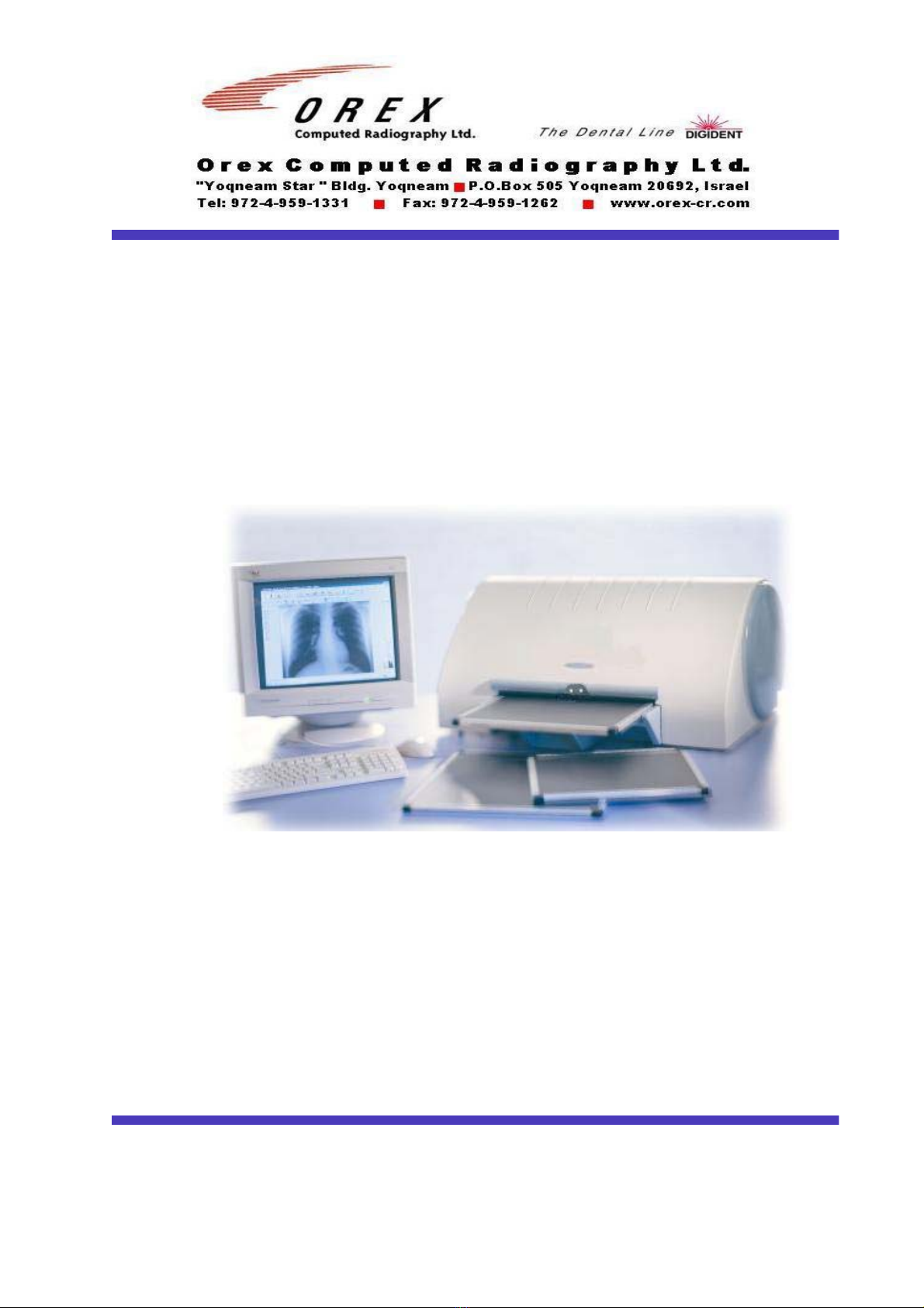
1. PcCR 1417 System Introduction .........................................................................................1
1.1 Overview ..................................................................................................................1
1.2 PcCR 1417 Operational Principles...........................................................................1
1.3 Scanner Mechanical Description..............................................................................2
1.4 Features ....................................................................................................................3
1.5 Technical Information and Specifications................................................................4
2. Using the PcCR 1417 System...............................................................................................5
2.1 Overview ..................................................................................................................5
2.2 Language Support ....................................................................................................5
2.3 Using the Image Plate with Cassette........................................................................7
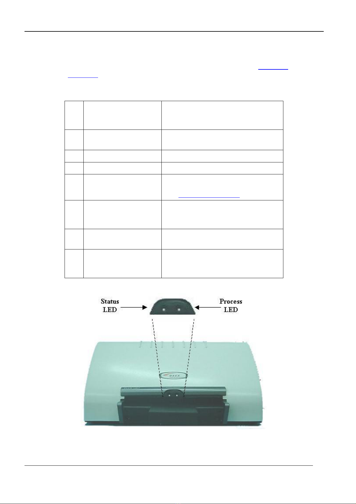
2.4 Plate Scanning Process.............................................................................................9
2.5 Entering The Setup Menu ......................................................................................17
2.6 Changing a PM Gain Value ...................................................................................18
2.7 Adjusting the System to an X-ray Unit ..................................................................20
2.8 Adding and Deleting Sub-organs ...........................................................................21
3. X-ray Machine-to-Scanner Calibration ...........................................................................22
3.1 Overview ................................................................................................................22
3.2 Calibration Procedure.............................................................................................22
4. Image Property ...................................................................................................................27
4.1 Overview ................................................................................................................27
4.2 Selecting an Image Path .........................................................................................27
5. Resolution, Orientation and Linearization ......................................................................28
5.1 Overview ................................................................................................................28
5.2 Setting Resolution, Orientation and Lineariztion...................................................28
6. Erasing Options and Automatic Scan ..............................................................................30
6.1 Overview ................................................................................................................30
6.2 Setting Erasing Options and Auto Scan .................................................................31
7. RAIS 2 .................................................................................................................................32
8. About OREX Software ......................................................................................................35
9. Troubleshooting..................................................................................................................36
9.1 Overview ................................................................................................................36
9.2 Error List ................................................................................................................36
9.3 Frequently Asked Questions ..................................................................................37
10. Recording Sub-Organ Offset and PM Gain Values ........................................................38
11. Cleaning the Rollers ...........................................................................................................40
11.1 Overview ................................................................................................................40
11.2 Using the Cleaning Plate to Clean the Rollers .......................................................40
12. Demo Scan...........................................................................................................................43
13. Installing Context Vision ...................................................................................................45
iii

List of Figures
Figure 1-1: PcCR 1417 Front View.................................................................................................2
Figure 1-2: PcCR 1417 Back View .................................................................................................3
Figure 2-1: AC Power and USB Cable Connections .....................................................................10
Figure 2-2: Loading the Cassette ...................................................................................................11
List of Abbreviations
FAQ – Frequently Asked Questions
LED – Light Emitting Diode
USB – Universal Serial Bus
GUI – Graphic User Interface
iv

Preface
This manual provides all the required information for scanning a medical plate using
the OREX PcCR 1417 reader. The manual is intended to be used by medical
personnel, and is comprised of the following sections:
Section 1: PcCR 1417 System Introduction
This section includes the PcCR 1417 System operation principles,
mechanical description, technical information, features, and
instructions on how to clean plates.
Section 2: Using the PcCR 1417 System
This section provides a general flowchart and step-by-step instructions
on how to scan and erase a plate using the PcCR 1417 System, and
instructions on how to change the photo multiplier gain (PM gain)
value of a poor or overexposed image.
Section 3: X-ray Machine-to-Scanner Calibration
This section provides step-by-step instructions on how to calibrate the
scanner to the local x-ray machine.
Section 4 Image Property
This section provides instructions for selecting an image format and location.
Section 5 Resolution, Orientation and Linearization
This section provides instructions for selecting a scanning resolution
and an image orientation, and for using the Linearization algorithm.
Section 6 Erasing Options and Automatic Scan
This section provides instructions for controlling the film erasing time
and working with the automatic scan/erase mode.
Section 7 RAIS 2
This sections describes the dual scan feature, mostly used for on-the-
spot study display.
Section 8 About OREX Software
This section depicts the layers of the system’s software, and the number
of scans performed since last reset.
Section 9 Troubleshooting
This section provides general guidelines for correcting malfunctions
that may occur while using the PcCR 1417 System, and answers to
Frequently Asked Questions (FAQs).
Section 10 Recording Sub-Organs Offset and PM Gain Values
This section provides a place for you to record the PM gain values you
set for various organs/sub-organs.
v

Section 11 Cleaning the Rollers
This section explains how to clean the rollers of the scanner with the
cleaning plate.
Section 12 Demo Scan
This section explains how to display a demonstration image on your
computer screen without connecting to the scanner.
Section 13 Installing Context Vision
This section walks you through installing the Context Vision filter.
Safety Summary
LIFTING HAZARD
The PcCR 1417 scanner weighs 40 Kg (88 lb). Do not try to lift the scanner
by yourself. Always seek assistance from another person. Lifting equipment
that is too heavy may result in serious injury to personnel and/or damage to
equipment.
WARNING
The PcCR 1417 scanner is a CLASS 1 Laser product.
- Do not remove the scanner cover!
- Cover removal should be done only by authorized service personnel!
Laser Safety Instructions
1. During normal operation, the scanner should always be enclosed in its
protective cover. This is to prevent the outside area from being exposed to
laser.
2. During normal operation, the cover should not be removed. Removing the
cover should only be done for service purposes by a qualified technician.
vi

1. PcCR 1417 System Introduction
1.1 Overview
The OREX PcCR 1417 System is used by medical personnel for reading phosphor
x-ray plates (CR).
The system is composed of two main parts:
• The OREX PcCR 1417 scanner (see Figure 1-1).
• The PcCR 1417 software package, that includes:
• The OREX Scanner
Interface software that
operates the scanner.
• An image viewing and
archiving software package
that supports the DICOM 3.1
standard and was approved
by OREX, such as HIPAX.
The following depicts the PcCR 1417 System operational principles, mechanical
description, technical information, features, and instructions on how to handle and
clean plates.
1.2 PcCR 1417 Operational Principles
The PcCR 1417 is a machine used for digital image acquisition and processing of
static projection radiography. The PcCR 1417 uses a phosphor plate with energy
storage capability as an x-ray image receptor.
After exposure, a laser beam, which stimulates luminescence proportional to the
local x-ray exposure, reads the plate. The luminescence signal is digitized. The
data is then subjected to digital image processing.
The OREX PcCR 1417 reader enables the user to read a plate quickly, and erase it
to be ready for the next read. The reader is compact and easy to use.
The main advantage of the PcCR 1417 system is that it enables radiologists to “go
digital” without changing their work practices or x-ray equipment.
1

1.3 Scanner Mechanical Description
The following depicts the scanner’s main parts and functions (see Figure 1-1 and
Figure 1-2):
N
o
.
Item Function
1. Cassette Tray Inserts the cassette into the reader for
reading and erasing.
2. 10" Width Plate Adapter Loads a centered 10" width plate.
3. 14" Width Plate Adapter Loads a centered 14" width plate.
4. SYSTEM LED
PROCESS LED
Indicate the status of the scanner.
(see Status Indicator chart in section 2)
5. Power Connector Connects the scanner to a power
source. (120VA/100–240 VAC @
50/60 Hz).
6. ON/OFF
Power Switch
Turns the scanner ON/OFF.
7. USB Connector Connects the reader to your computer,
by using the USB communication
protocol.
Figure 1-1: PcCR 1417 Front View
2

Figure 1-2: PcCR 1417 Back View
1.4 Features
• Large (14” x 17”) digital image reading and viewing archive.
• Plug and Play USB interface.
• The PcCR 1417 reader follows the provisions of the Medical
Device Directive 93/42 EEC for class 1 Devices.
The reader conforms with the following safety standards:
• EN60950 (1992)
• IEC60825-1 (1993-11)
• IEC60601-1-2 (1993)
The CE mark that is used on OREX products is .
3

1.5 Technical Information and Specifications
Scanning
Resolution
Standard format 14” x 17”
Standard format 14” x 14”
Normal format 10” x 12”
Normal format 8” x 10”
High resolution 8” x 10”
2.5 Lp/mm
2.5 Lp/mm
3.5 Lp/mm
3.5 Lp/mm
4.2 Lp/mm
8" x 10" plate size 110 x 110 µm pixel size
(or 100 x 100 µm at high
resolution)
10" x 12" plate size 126 x 126 µm pixel size
14" x 14" plate size 173 x 173 µm pixel size
Plate and Pixel Size
14" x 17" plate size 173 x 173 µm pixel size
Plate Type AGFA ADC-MD-30
(produced and licensed to OREX by AGFA-GEVAERT A.G.)
Reading Time 8" x 10" plate size
10" x 12" plate size
14" x 14" plate size
14" x 17" plate size
130 sec. ±10%
120 sec. ±10%
113 sec. ±10%
113 sec. ±10%
Erasing Time 8" x 10" plate size
10" x 12" plate size
14" x 14" plate size
14" x 17" plate size
35 sec. ±10%
45 sec. ±10%
52 sec. ±10%
62 sec. ±10%
Read/Erase cycle
time
8" x 10" plate size
10" x 12" plate size
14" x 14" plate size
14" x 17" plate size
165 sec. ±10%
165 sec. ±10%
165 sec. ±10%
175 sec. ±10%
File Size 10–13 MB (uncompressed) maximum, Up to 1 MB compressed
Reader Dimensions 78 cm x 64 cm x 34 cm (30.7" x 25.2" x 13.4")
Weight 40 Kg (88 lb)
Power Consumption 120VA/100–240 VAC @ 50/60 Hz
Environmental
Operating
Conditions
Temperature
Relative Humidity
Ambient Lighting
18–30 °C (normal lab conditions)
80% (max) non-condensing
Less than 1000 Lux
Reading Laser
Specifications
Visible Light Output
Max Output Power
635 nm–650 nm
30 mW
Customer's
Computer Min.
Requirements
Type
Operating System
Internal Memory
I/O Interface
Required Disc Space
Modem (for remote scanner
servicing)
UPS (APC or equivalent)
PIV, 1.8GHz or above
Win 2000
256M RAM (minimum)
USB 1.1
60M Bytes (for OREX
software package only)
4

2. Using the PcCR 1417 System
2.1 Overview
2.2
This section provides a general flowchart and step-by-step instructions on how to
scan a plate using the PcCR 1417 System, and instructions on how to change the
photo multiplier (PM) gain value of a poor or over exposed image.
Language Support
The PcCR 1417 system supports interface in different languages.
NOTE:
To enable language support, ensure that your computer runs on a Windows 2000,
system (English version).
To change the interface language
1. From the Desktop go to Settings ÎControl Panel; then
double-click the Regional Settings icon.
2. From the Change Locale pull-down menu, choose the
required language; for example, Chinese (PRC).
3. Click Set as default; then select the same language
again; for example, Chinese (PRC).
4. At the prompt, select Yes.
5. Check that the chosen language support is installed on
your computer.
6. Click OK to reboot the computer.
5

7. The computer restarts, running all applications,
including the PcCR 1417, with the selected language.
8. If the language used is Chinese, enter the Scanner
Interface – the Advanced tab.
9. From the Language drop-down menu, select
Chinese RPS.
6

2.3 Using the Image Plate with Cassette
An image plate comes in a cassette, and should remain there. The only time a plate
is out of the cassette is when the scanner automatically loads the plate for reading.
It is important to keep the image plate positioned correctly throughout any
procedure.
7

To load a cassette into the reader:
1. Verify that the scanner is On, and that the System LED is
green, indicating that the scanner is ready.
2. Insert the cassette into the scanner:
• The face (white) side faces up,
• The open edge points toward the scanner, and
• The cassette is centered exactly from side to side in the scanner slot.
The cassette locks when it reaches its proper position in the scanner. Once the
cassette locks, the image plate loads automatically.
Ordinarily, the cassette unlocks automatically after scanning, ready for re-use. In
case you need to unlock the cassette manually, pull the screw beneath the slot to
unlock the cassette.
8

2.4 Plate Scanning Process
The following flowchart depicts how to read a plate using the PcCR 1417 Reader.
The reading process is comprised of the following stages:
• Verifying the Prerequisites for Scanning
• Launching the Scanner Interface Software
• Loading a Cassette
• Setting Up the Reader
• Scanning and Erasing a Plate
9

2.4.1 Verifying the Prerequisites for Reading
Before the scanner reads the plate, check that the following conditions
exist:
• The USB cable connects your computer to the reader
(see Figure 2-1). When using the RAIS 2 option, it is possible to
connect two readers to one computer.
• The reader is connected to the AC Power source (see Figure 2-1).
• The reader and scanning driver were configured and calibrated
during installation by OREX authorized service personnel.
Figure 2-1: AC Power and USB Cable Connections
2.4.2 Launching the Scanner Interface Software
1. Switch ON the scanner Power Switch (see
Figure 1-2).
2. If you are using Orex CRW, launch this
program. For other programs, please get
instructions from OREX authorized service
personnel.
3. Insert a new patient file, or select an existing
patient file.
4. Click the Scan icon to start the scanning process.
• The OREX Scanner Interface main dialog opens.
• The scanner starts communicating with the computer.
• Within a few seconds, check that the scanner SYSTEM LED
turns green (see Figure 1-1), and the Insert plate message is
displayed on the main dialog.
5. Proceed with the following procedure, Loading a Cassette.
10

2.4.3 Loading a Cassette
Figure 2-2: Loading the Cassette
1. Place and center the cassette on the Cassette
Tray (10" or 14" cassette width, shown in
Figure 1-1).
2. Slightly push the cassette into the scanner (Figure 2-2) until it clicks
into the locked position, and the PROCESS LED turns orange and
starts blinking.
• The plate is automatically "pulled" and loaded into the scanner.
• The PROCESS indication LED changes from orange to green.
• In the Scanner Interface’s main dialog, the Scan, Erase, Exit,
Setup and Eject functions turn valid.
The reader is now in the correct condition to scan the loaded
plate. The Plate “inch” x “inch” is ready... message is
displayed on the main dialog.
At this point, you can choose to perform any of the following
actions:
• Unload the plate by clicking Eject.
• Erase the loaded plate by clicking Erase.
• Cancel and close the Scanner Interface by clicking Exit.
• Scan the loaded plate. Proceed with the following procedure,
Setting Up the Scanner.
If no scanning is performed within 2 minutes, the cassette is
ejected automatically.
11

2.4.4 Setting Up the Scanner
1. Click the Setup button in the scanner interface. The Setup dialog box
opens. In the Setup dialog box, select the Configuration tab.
2. To set the size of the area to be scanned, left click the Plate “inch” x
“inch” is ready… message. A drop-down-list appears. From the drop-
down list, select the desired holder size. A 14” x 17” holder can be read
partially by selecting a smaller holder size.
3. Select an Organ and a Sub-Organ by clicking the image of the body on
the left side of the main dialog.
a. Point your cursor at one of the body organs on the image.
A popup menu opens.
b. From the popup menu, select the sub-organ you want to scan.
4. Proceed with the following procedure, Scanning and Erasing a Plate.
12

2.4.5 Scanning and Erasing a Plate
IMPORTANT
While scanning, do not perform any other operation on your computer
(for example, printing, network operation, or emailing). These
operations may result in errors in the scanning process.
1. To begin scanning, click the Scan button.
First the Initializing scanning,and then the Scanning messages are
displayed on the main dialog.
If you want to stop the reading process, click the Abort button The plate is
automatically unloaded from the reader into the cassette without being erased.
While scanning, you can see these things:
• The scanner’s SYSTEM LED (see Figure 1-1) turns orange,
and the PROCESS LED is green.
• You can view the scanned image in the Image Preview
window.
• A countdown timer is displayed, indicating the time left for
reading the plate.
13

When the scanner has finished reading the plate, the digital image
appears on the viewer.
• If Auto erase has been set in advance, an Erase message
appears after scanning is completed. To view the Erase
message, you must re-activate the Scanner Interface.
• If Auto erase hasn’t been set in advance, insert the film, and
wait for system initialization to be completed. When the
Plate “width” x “length” is ready... message is displayed on
the main dialog, press the Erase button. A countdown timer
is displayed only in the non-automatic erasing mode.
2. Save the scanned image in the patient folder.
You have completed the plate scanning process.
At this point you can re-use the scanned and erased plate.
14
Other manuals for PcCR 1417
2
This manual suits for next models
1
Table of contents
Other OREX Medical Equipment manuals