OREX PcCR 1417 ACL4 User manual

PcCR 1417 ACL4 System
(AA095042-00)
Automatic Cassette Loading Version
Service Manual
Catalog number: AT095005-02
September, 2003 Ver. 01

OREX Ltd. is a market innovator in the field of portable Computed Radiography
Technologies—designed and priced for low-volume clinic or field unit needs.
Founded in 1995 under the name of Digident, the company initially entered the market of
desktop dental radiography providing high quality, portable CR reading units for dental and
orthodontic professionals around the world. The secret of Digident/OREX’s rapid success lies
in the best cost-performance ratio on the market.
OREX designs, manufactures and markets phosphor image laser scanners. These units replace
the traditional x-ray film and light box. The scanners allow the user to immediately read the
x-ray image from the phosphor plate, and transfer it to a DICOM 3 compatible digital
computer file. Once transferred, users can manipulate the digital image for close-up
screening, or transmit it for long-distance consultation. After each scan, the phosphor plates
are automatically erased by the unit, ready for re-use.
OREX provides clients with a full solution including phosphor image plates, laser readers,
software for image processing, storage, retrieval and communication in Picture Archiving and
Communications System (PACS) compatible format.
The company’s mission is to become a leading provider of compact personal CR systems.
Following the successful penetration of the global dental market, the company changed its
name from Digident to OREX and expanded its markets and product lines to serve the dental,
medical, military, industrial and veterinary fields.
“We are committed to assisting our customers in obtaining maximum value
from OREX products by providing excellent support at exceptional value.”
Technical Support
Israel Headquarters: Tel: ++972-4-959-1331
Fax: ++972-4-959-1262
US Office: Tel: ++1-617-244-9000
Toll free: 1-888-844-7775 (within US only)
Fax: ++1-617-244-9020
Document Part Number: AT095005-02
Printed in Yokneam, Israel 2003
Copyright © 2002, all rights reserved
Page ii

Page iii
Safety
Laser Safety Instructions
1. During nominal operation, the scanner is closed
and sealed with a protective cover. That is for
preventing the laser from being exposed to the
outside area, and to prevent access to the laser by
the user.
2. During nominal operation, the cover should not be
removed. Removing the cover shall be done only
for service purposes, and by a qualified technician
for service operations.
3. Any service operation shall be done without
activating the laser unit. Disconnecting the relevant
connector on the laser board will disconnect the
power supply to the laser, and deactivate the laser
unit for service operations.
4. In case the laser must be operated during service
operation, the service technician shall make sure
that the optical unit is located within the cylinder
area, where the laser beam is blocked and cannot
leak outside.
5. When a service operation is taking place, with
cover removed and laser activated, avoid direct
exposure to the laser beam.

Table of Contents
1. Terms and Conventions .........................................................................................1
2. Required Tools for FSE .........................................................................................2
3. Component Description .........................................................................................3
3.1 GENERAL ........................................................................................................3
3.2 SYSTEM BLOCK DIAGRAM ..............................................................................4
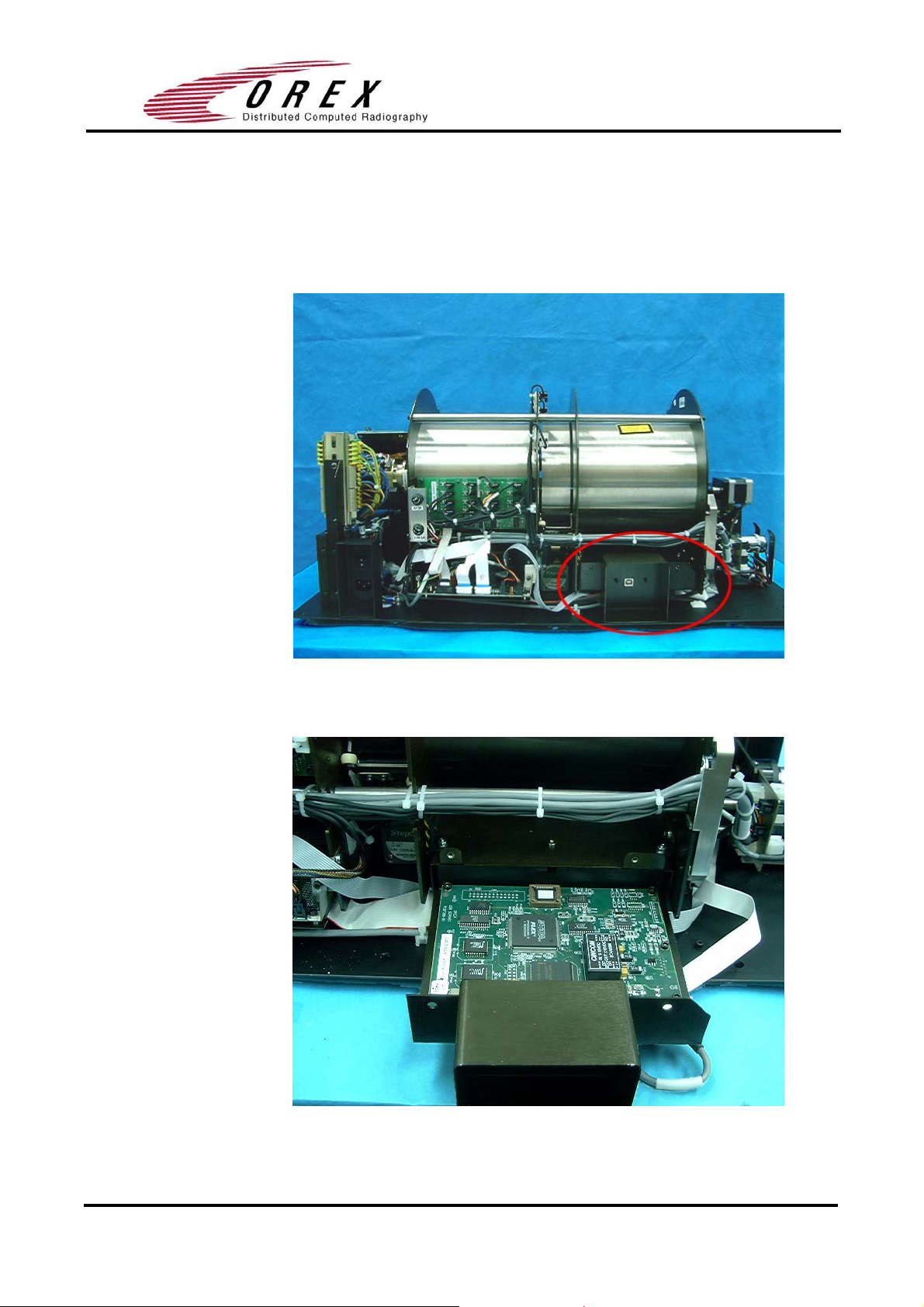
3.3 USB BOARD ...................................................................................................5
3.3.1 Location .................................................................................................5
3.3.2 Component.............................................................................................5
3.3.3 Description.............................................................................................6
3.4 MOTION BOARD..............................................................................................7
3.4.1 Location .................................................................................................7
3.4.2 Component.............................................................................................7
3.4.3 Description.............................................................................................8
3.5 SENSOR BOARD.............................................................................................10
3.5.1 Location ...............................................................................................10
3.5.2 Component...........................................................................................10
3.5.3 Description...........................................................................................11
3.6 PM ASSEMBLY .............................................................................................12
3.6.1 Location ...............................................................................................12
3.6.2 Component...........................................................................................13
3.7 LASER BOARD...............................................................................................13
3.7.1 Location ...............................................................................................13
3.7.2 Component...........................................................................................14
3.7.3 Description...........................................................................................14
3.8 LASER ...........................................................................................................15
3.8.1 Location ...............................................................................................15
3.9 ROLLER MOTOR............................................................................................16
3.9.1 Location ...............................................................................................16
3.9.2 Component...........................................................................................17
3.9.3 Description...........................................................................................17
3.10 STEP MOTOR SLIDE ......................................................................................18
3.10.1 Location ...............................................................................................18
3.10.2 Component...........................................................................................18
3.10.3 Description...........................................................................................19
3.11 STEP MOTOR CARRIAGE ...............................................................................20
3.11.1 Location ...............................................................................................20
3.11.2 Component...........................................................................................20
3.11.3 Description...........................................................................................21
3.12 POWER SUPPLY ASSEMBLY...........................................................................22
3.12.1 Location ...............................................................................................22
3.12.2 Component...........................................................................................22
3.12.3 Description...........................................................................................23
3.13 ERASE LAMPS SENSOR..................................................................................24
3.13.1 Location ...............................................................................................24
3.13.2 Component...........................................................................................24
Table of Contents Page iv

3.13.3 Description...........................................................................................25
3.14 LEFT ORIGIN SENSOR....................................................................................26
3.14.1 Location ...............................................................................................26
3.14.2 Component...........................................................................................26
3.15 RIGHT ORIGIN SENSOR .................................................................................27
3.15.1 Location ...............................................................................................27
3.15.2 Component...........................................................................................27
3.16 PLATE SIZE SENSOR ......................................................................................28
3.16.1 Location ...............................................................................................28
3.16.2 Component...........................................................................................28
3.17 ROLLERS SENSOR..........................................................................................29
3.17.1 Location ...............................................................................................29
3.17.2 Component...........................................................................................29
3.18 ERASE LAMPS ...............................................................................................30
3.18.1 Location ...............................................................................................30
3.18.2 Component...........................................................................................30
3.18.3 Description...........................................................................................31
3.19 INVERTERS ASSEMBLY..................................................................................32
3.19.1 Location ...............................................................................................32
3.19.2 Component...........................................................................................32
3.19.3 Description...........................................................................................33
4. Preventive Maintenance.......................................................................................34
4.1 CLEANING THE ROLLERS ..............................................................................34
4.1.1 Overview..............................................................................................34
4.1.2 Using the Cleaning Plate to Clean the Rollers.....................................34
5. Service Operation.................................................................................................37
5.1 REMOVING THE COVER .................................................................................37
5.1.1 Main Cover ..........................................................................................37
5.1.2 Service Panel........................................................................................38
5.2 REPLACING THE USB BOARD .......................................................................39
5.3 REPLACING THE MOTION BOARD..................................................................40
5.4 REPLACING THE SENSOR BOARD ..................................................................41
5.5 REPLACING THE PM TUBE AND PM BOARD .................................................42
5.6 REPLACING THE LASER BOARD.....................................................................44
5.7 REPLACING THE ROLLER MOTOR..................................................................45
5.8 REPLACING THE SLIDE ..................................................................................47
5.9 REPLACING THE STEP MOTOR CARRIAGE ......................................................51
5.10 REPLACING THE POWER SUPPLY ASSEMBLY.................................................54
5.11 REPLACING THE ERASE LAMPS INVERTERS ...................................................58
5.12 REPLACING THE ERASE LAMPS SENSORS ......................................................60
5.13 REPLACING THE LEFT ORIGIN SENSOR..........................................................62
5.14 REPLACING THE RIGHT ORIGIN SENSOR .......................................................63
5.15 REPLACING THE PLATE SIZE SENSOR............................................................64
5.16 REPLACING THE ROLLERS SENSOR ...............................................................66
5.17 REPLACING THE ERASE LAMPS .....................................................................69
6. Appendix A: Service Report................................................................................72
Table of Contents Page v

1. Terms and Conventions
Term Meaning
FSE Field Service Engineer
PSP Photo-Stimulate Plate
USB Universal Serial Bus
PM Photo multiplayer
Terms and Conventions Page 1 of 1

2. Required Tools for FSE
•Philips screw driver PH2
•Open end spanner 7.0mm
•Hexagon (Allan) key 1.5mm
•Hexagon (Allan) key 2.0mm
•Hexagon (Allan) key 3.0mm
•Hexagon (Allan) key 4.0mm
•Sharp nose pliers
•Electronic Side cutters
Required Tools for FSE Page 2 of 2

3. Component Description
3.1 General
The PcCR 1417 consists of 16 major assemblies, which can be replaced in
the field in case of malfunction.
USB BOARD
MOTION BOARD
SENSOR BOARD
PM +PM BOARD
LASER BOARD
ROLLER MOTOR
STEP MOTOR SLIDE
STEP MOTOR CARRIAGE
POWER SUPPLY ASSEMBLY
ERASE LAMPS SENSORS
L-ORIGIN SENSOR
R–ORIGIN SENSOR
PLATE SIZE SENSOR
ROLLERS SENSOR
ERASE LAMPS
INVERTERS ASSEMBLY
This chapter includes description for each part,
including its location and wiring.
Component Description Page 3 of 3

3.2 System Block Diagram
Component Description Page 4 of 4

3.3 USB Board
3.3.1 Location
3.3.2 Component
Component Description Page 5 of 5

3.3.3 Description
Connector 1 Destination: USB connector on pc.
Connector 2 Serial EPROM
Destination: 5v/12v power supply.
1 Red 5v
3 Black GND
Connector 3
J305
4 Yellow 12v
Connector 4
J300
Destination: flat cable to J1 on pm card.
Connector 5
J304
Destination: flex cable to J200 on motion card.
Component Description Page 6 of 6

3.4 Motion Board
3.4.1 Location
3.4.2 Component
Component Description Page 7 of 7

3.4.3 Description
Destination: J500 on sensor card
Connector 1
J208
Destination: J401 on laser card.
Connector 2
J203
Destination: J1 on front panel led card.
Connector 3
J205
Component Description Page 8 of 8

Destination: 12v power supply.
12vorange1
Connector 4
J213
Destination: connectors panel (rollers motor).
12vorange1
GNDBrown2
Rollers forward +12v ; rollers backwards -12v ; rollers
stop 0v
Connector 5
J206
Voltage on J206:
Destination: J2 on enhanced motion card.
Connector 6
J202
Destination: loader.
130Hz load/unloadOrange + blue
130Hz load/unloadRed + yellow
Connector 7
J204
Destination: connectors’ panel to stepper motor.
11KHz moving left/right ;
0KHz stop
Yellow + black
11KHz moving left/right ;
0KHz stop
Blue + white
Connector 8
J201
Destination: 15v power supply.
GNDblack1
15vred2
Connector 9
J211
Destination: 5v power supply.
GNDblack1
5vred2
Connector 10
Destination: J302 on USB card.
Connector 11
J200
Component Description Page 9 of 9

3.5 Sensor Board
3.5.1 Location
1.
3.5.2 Component
2.
Component Description Page 10 of 10

3.5.3 Description
J513 J514 J515 J516
J509 J510 J511 J512
J505 J506 J507 J508
J501 J502 J503 J504
J500
J500 connector connects to J208 on motion card.
J501 connects to sensor 4 on the drum.
J502 connects to sensor 5 on the drum.
J505 connects to sensor 1 on the drum.
J506 connects to sensor 2 on the drum.
J507 connects to sensor 3 on the drum.
J508 connects to loader sensor in back position.
J509 connects to roller sensor.
J511 connects to W0 sensor.
J513 connects to cassette presence sensor.
J514 connects to cassette lock sensor.
J515 connects to right limit sensor.
J516 connects to left limit sensor.
Typical Sensor connections
Connector Sensor
1
(Brown)
5v
2
(White)
Signal
3
(Blue)
GND
4
Not in
use
Sensor on 1 Brown 5v always
Component Description Page 11 of 11

2 White 0v
3 Blue GND always
(Flag in sensor)
4 Not in use
1 Brown 5v always
2 White 5v
3 Blue GND always
Sensor off
(Flag not in
sensor)
4 Not in use
Note:
Measuring voltage:
1. All sensors except J511: measure between pin 2 & 3 and insert object
between sensors.
2. For J511 only: measure between pin 2 & pin 3 from different sensor and
insert cassette to system. The voltage should be between 4.5-5v.
3.6 PM Assembly
3.6.1 Location
Component Description Page 12 of 12

3.6.2 Component
Destination: J300 on USB card.
3.7 Laser Board
3.7.1 Location
Component Description Page 13 of 13

3.7.2 Component
3.7.3 Description
Destination: J203 on motion card.1
Destination: encoder reader.2
GNDRed1
Index 41±0.5 HzBlack2
Encoder 41± 0.5 KHzBlue3
5vYellow4
Component Description Page 14 of 14

Destination: rotation motor card.3
GNDBrown1
12v rotation motor on.Blue2
Destination: laser assembly.4
Laser On 3.3VRed1
GNDBlack2
3.8 Laser
3.8.1 Location
Component Description Page 15 of 15
Other manuals for PcCR 1417 ACL4
2
This manual suits for next models
1
Table of contents
Other OREX Medical Equipment manuals