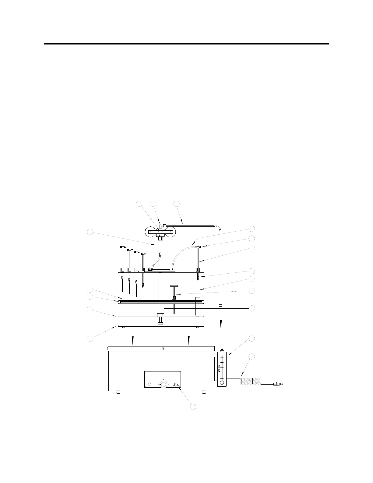
Organomation Associates N-EVAP 111 User manual

Nitrogen Evaporation System
Models 111, 112, 115
INSTRUCTION MANUAL
ORGANOMATION ASSOCIATES INC.
266 RIVER ROAD WEST
BERLIN, MA 01503
U. S. A.
Tel: 888-838-7300 Fax: 978-838-2786
TM
N-EVAP


TABLE OF CONTENTS
N-EVAPTM
Introduction
Instrument Items Shipped
Instrument Description
Instrument Part Identification
Safety Labeling and Descriptions
Installation
Location
Bath Setup
Instrument Setup
Safety Considerations - Read before operation
Operation
Instrument Control Identification
Planning and Preparation
Type Z Purge Intrinsically Safe Bath Option
Bath Operation
Instrument Operation
Optimization
Maintenance and Cleaning
Trouble Shooting
Technical Information
Parts List
Service and Returns
Shipping - Claims for damage or shortage
Specifications
UL - Underwriters Laboratories
Warranty
Wiring Diagrams
Z-Purge NFPA Guidelines
Accessories
Other Products and Services
Contacting Organomation and its Representatives
Product designs are subject to change without notice
© 2003 Organomation Associates Inc.
Printed in U. S. A.
N03.0


266 River Road West
Berlin MA 01503-1699 USA
Tel: 888 838-7300 Fax: 978 838-2786
e.mail: sales@organomation.com
Dear Customer,
Thank you for choosing a Sample Preparation Instrument from Organomation
Associates. We appreciate your business and believe that the instrument and
accessories you purchased will work very satisfactorily for many years to come.
Whether you have added another instrument to your laboratory, or have purchased
one for the first time, we will stand behind our equipment.
Should you have questions regarding the set up or operation of this instrument or
questions regarding other Organomation products please contact us. The toll free
telephone number for sales support and customer service is 888 838-7300. If you
purchased the instrument through one of our dealers you should contact them first.
Any comments from you would be much appreciated. We listen to our customers
which, in turn, enables us to provide the best instruments available. Please fill out the
Warranty and Service Registration Form and return it within ten days of receipt of
instrument. Once we have the completed form, your warranty will be activated as
stated. The Warranty Form can be mailed or faxed to us at 978 838-2786.
The operating manual contains literature and product lists describing our complete
line of laboratory instruments. It provides a convenient way to order new instruments,
accessories or repair parts. If you need a verbal or written quote on specific items
please call us at our toll free number or e.mail us at the address above.
Again, thank you for selecting ORGANOMATION ASSOCIATES products.
Sincerely,
Andrew McNiven
President
Sample Preparation Instruments for Analytical Laboratories Since 1959

N03.0
INTRODUCTIONN-EVAP
Items Shipped
Carefully check the contents of all cartons received for damage which may have
occurred in transit. Retain all cartons and packaging materials until all components have been
checked against the packing slip, the component list below, and the equipment has been
assembled and tested. Contact Organomation Associates Inc. immediately if any damage or
discrepancies are found.
Your shipment should contain one or more of the instruments shown below. Option codes are
listed on the next page.
Instrument Size
12 Position N-EVAP Nitrogen evaporation system
24 Position N-EVAP Nitrogen evaporation system
36 Position N-EVAP Nitrogen evaporation system (Obsolete - replaced by 11634)
Flowmeter Assembly with Mounting Bracket & Connector Tube
0-10 LPM for 12 position N-EVAP
0-20 LPM for 24 position N-EVAP
0-30 LPM for 36 position N-EVAP
Thermometer 0 - 100ºCelsius
19ga x 4” Stainless Steel Luer Lock Needles, blunt end
1 Dz for 12 Position N-EVAP
2 Dz for 24 Position N-EVAP
3 Dz for 36 Position N-EVAP
OA-SYS Water Bath 500W, for 12 position N-EVAP
OA-SYS Water Bath 800W, for 24 position N-EVAP
OA-SYS Water Bath 1200W, for 36 position N-EVAP
SS Gas Tube 1/4” (7mm) OD, 24 and 36 position only
T-Handle Hex Key adjustment tools
1 ea. 1/8” x 6” Long, for 12 & 24 position N-EVAP
1 ea. 5/32” x 6” Long, for 12 & 24 position N-EVAP
1 ea. 5/32” x 9” Long, for 36 position N-EVAP
Manual for N-EVAP models 11155, 11250, 11550
Pasteur Pippet Adapter with flow controller, 1 Dozen per set (Optional)
Cat #
11155
11250
11550
NA1124
NA1221
NA1521
NA1110
NA0603
B1102
B1201
B1501
V11291
V10127
V10128
V11437
V10124
NA0636
N-EVAP and OA-SYS are Trademarks of Organomation Associates Inc.
- 1 -

N03.0
INTRODUCTION
N-EVAP ™
Option Codes and additional items shipped
The following list contains option codes and items which may have been shipped in
conjunction with the standard parts shown on the previous page. Please check your packing
list and order information carefully to determine if these items are included in your shipment.
For a complete list of available accessories, please refer to the Accessories Section.
Your shipment may contain the following optional items:
Description
OA-SYS water bath supplied with digital controller (Model 111 only)
12, 24, or 36 position N-EVAP Instrument ordered without OA-SYS
water bath, includes a flowmeter mounting bracket (included with
flowmeter) for direct mounting to stand base versus to the bath.
Pasteur Pipet Adapters replace SS needles on the N-EVAP. 1, 2, or 3
dozen are provided with the respective N-EVAP size ordered, reference
part # NA0637. Includes glass pipet sample pack.
12, 24, or 36 position N-EVAP Instrument and OA-SYS water bath are
coated in Teflon. Instrument is black in color. The water bath is blue on
the outside and black on the inside.
Pasteur pippet adapters as above, provided with Teflon coated unit.
SS Needles 19 gauge x 4” (100mm) Long, are coated in Teflon and are
black in color.
OA-SYS water bath has been modified for the Type-Z Purge Intrinsically
Safe bath option. Additional parts include: differential pressure gauge,
mounting bracket, and tubing.
OA-SYS water bath is wired as a 240 Volt unit.
16 gauge x 4” needles replace 19 gauge x 4” needles.
OA-SYS Heating Unit for use with dry media, aluminum or glass beads.
The support tray is deleted from the instrument. Aluminum or glass me-
dia is provided.
Option
-E
-0
-P
-R
-RP
-RT or -T
-Z
-2
-16
-DA or -DG
Teflon is a registered Trademark of EI Dupont Inc.
- 2 -

N03.0
INTRODUCTION
N-EVAP ™
Instrument Description
The N-EVAP Nitrogen Evaporation System is designed for general evaporation and / or
concentration of analytical or biological samples in a variety of test tube based glassware under
controlled and reproducible conditions.
The instrument portion is circular and is designed to hold test tubes from 10 to 29 mm
OD. The unit will rotate in any direction and may be raised or lowered at will. 24 position
and larger units have spring lift assemblies. The instrument may be used with OA-SYS or oth-
er heating baths or may be ordered as a standalone unit. Construction is primarily 304 stain-
less steel, anodized aluminum, chrome plated brass, and Delrin (Acetal). Unit may be used
with SS needles or disposable glass pipets. Coating in Teflon is available for acidic applica-
tions. All tubing provided is Phthalate free.
The complete instrument is shown below.
Figure 1 - Model 112 shown
Organomation Associates Inc.
HEAT
POWER
OA-SYS
N-EVAP
266 River Road West
Heating System
TM TM
ON
OFF
LOW
HIGH
1
234567
8
9
1
2
3
4
5
1
2
3
Berlin,MA 01503
4
5
6
78 9
10
11
12
13
14
15
16
17
18
- 3 -

N03.0
INTRODUCTION
N-EVAP ™
Item
(1)
(2)
(3)
(4)
(5)
(6)
(7)
(8)
(9)
(10)
(11)
(12)
(13)
(14)
(15)
(16)
(17)
(18)
*
Part Name
Water Bath
Stand
Support Tray
Sample Spring
Sample Holder
Filter
Hoist Assembly*
Swivel Fitting*
Gas Tube*
Silicone Tubing
Needle Valve
Valve Tube Assembly
Luer Fitting
Blunt Needle
Teflon coated
(Optional)
Thermometer
Center Tube Assem.
Flowmeter / Bracket
Connector Tube
Available on Models
112 &115 only.
Description
Round water bath, provides heat.
Supports N-EVAP in bath or bench.
Supports test tube samples.
Holds and centers samples.
Holds various sized samples.
Removes particles from gas stream.
Assists lifting of instrument.
Connects gas tube for unlimited rotation.
Delivers gas to rotating instrument.
Delivers gas to each Valve Tube
Assembly, Phthalate free.
Adjusts gas flow to each sample.
Delivers gas to each sample.
Connects needle or Pipet Adapter.
Delivers gas into sample tube.
Teflon coated (Optional)
Measures bath temperature.
Allows mounted hardware to rotate.
Meters gas flow to all samples at one
time.
Connects gas from source to the
flowmeter.
11155
B1102
P1125
P1114
P0614
P0628
NA0403
N A
N A
N A
P0610
P0629
P0626
P0607
NA0603
NA0603-T
NA1110
P1117
NA1124
NA1101
11550
B1501
P1525
P1514
P0614
P1503
NA0403
P1525
V11425
V11291
P1510
P0629
P0626
P0607
NA0603
NA0603-T
NA1110
P1505
NA1521
NA1101
11250
B1201
P1225
P1214
P0614
P0715
NA0403
P1224
V11425
V11291
P0710
P0629
P0626
P0607
NA0603
NA0603-T
NA1110
P1205
NA1221
NA1101
PARTS LIST
- 4 -

N03.0
INSTALLATION
N-EVAP ™
Location
The N-EVAP Evaporator System should be located on a bench top or in a chemical
fume hood if hazardous or flammable materials and solvents are to be used. The location
should provide the necessary support services for the instrument. These include electrical
power (required for water bath) and a clean inert gas source (Air or Nitrogen). Please review
the Specifications Section for further information.
Bath Setup
1. Position the bath on a stable flat surface such as a lab bench or in a chemical fume hood.
2. Turn the bath toggle switch to the “OFF” position.
3. Turn the bath thermostat knob to its lowest position.
4. Plug the bath electrical cord into a 3 wire grounded electrical outlet rated for 110-120
VAC, 50-60 Hz, single phase, 15 amps.
Optional 220 VAC baths are clearly marked and should be plugged into a 3 wire
grounded electrical outlet rated for 220-240 VAC, 50-60 Hz, single phase, 15 amps.
5. GFCI (Ground Fault Circuit Interrupter) is an optional safety device which may be
installed on the N-EVAP power cord. For 110-120 VAC baths, this item replaces the
plug at the end of the power cord. For 220-240 VAC baths, this item is located inline
on the power cord approximately 12 inches behind the plug. Please proceed to to the
next step if your bath does not have this item installed.
A. After the power cord has been plugged in. Depress the “RESET” button on the
GFCI to activate the unit.
NOTE: Any time the electrical power to the outlet is disrupted, the GFCI must
be reset.
B. The GFCI may be tested by simulating a “fault” condition. Depress the “TEST’
button, the GFCI will detect the failure and trip off. Depress the “RESET”
button to re-energize the GFCI.
C. If you encounter difficulty using the GFCI or the GFCI continually trips off
during bath use, please review the troubleshooting section or call
Organomation Technical Department for assistance.
6. Fill the bath with water to within 0.5 inch of the bath rim. The use of de-ionized water
will reduce mineral build up and extend bath operational life and is recommended.
- 5 -

N03.0
INSTALLATION
N-EVAP ™
Bath Setup (Continued)
7. Type-Z Purge Intrinsically Safe Bath option - If you do not have this option, please
proceed to the next section. Procedures for operating this system may be found in the
Operation Section. Quick start instructions are posted on the front of the bath. A copy
of the NFPA (National Fire Protection Agency) guidelines for intrinsically safe equip-
ment are in the appendix. Please refer to Figure 3 below for parts list and installation.
A. Install the Type Z Purge Gauge Assembly to the rear of the bath as shown. The
bracket attaches to the rear of the bath and is held in place by a 6-32 x 1/4”
screw on the shoulder spacer and by a 1/4” bulkhead hex nut on the gas inlet
fitting.
B. Connect the small white silicone tube attached to the gauge to the gas inlet
fitting using the compression nut provided.
C. Attach the filter with 5 foot tube to the plastic elbow fitting located at the base of
the bath. Insert the filter into the fitting and tighten the nut. Connect the tube
to a clean gas source.
D. Test the system by turning on the gas flow to the Z Purge System. Adjust the
gas flow until the gauge reads 0.1 inches water pressure.
WARNING - If this unit is located in a hazardous area where volatile fumes are
present, the Z-Purge System must be activated for a minimum of 10
minutes prior to activation of bath power. Please review the Safety and
Operations sections.
FIGURE 3
Gauge and Housing
1/4 White Silicone Tube
Tube Fitting Nut
3/8 OD Clear Tube
Bulkhead Hex Nut
Filter
Plastic Elbow Fitting
Flowmeter Bracket
Thermostat Knob
Shoulder Spacer
Gas Inlet Fitting
Front
Z-Purge Assembly Diagram - Side View
6/32 x 1/4 Screw
- 6 -

N03.0
INSTALLATION
N-EVAP ™
Bath Setup (Continued)
8. Flowmeter Assembly - Provided with all N-EVAP Systems. If an OA-SYS bath was
purchased without an N-EVAP instrument, proceed to the next section.
A. Attach the flowmeter to the bracket mounted on the bath with the two 10/32 x
1/2” screws provided. The meter should be positioned with the needle valve
facing forward and positioned closest to the bench.
B. Connect the Connector Tube to a clean gas source (Air or Nitrogen). Source
should be capable of being regulated from 0 to 30 psig. If source is above
30 psig, then Organomation part # NA0630 Pressure Reducing Regulator will
be required. Please consult Organomation Technical Support for assistance.
9. Pressure Reducing Regulator Option - If you do not have this option, proceed to the next
section. When purchased with an N-EVAP System, this item is pre-installed onto the
flowmeter, between the flowmeter and the Connector Tube. Refer to Figure 4 below.
A. Remove the flowmeter from the bracket.
B. Remove the Connector Tube and fitting from the flowmeter.
C. Connect the Pressure Reducing Regulator to the lower fitting on the back of the
flowmeter. Position the regulator such that the adjustment knob is straight up
and the gauge points away from the bath.
D. Connect the Connector Tube to the regulator.
E. Re-connect the flowmeter to the bracket.
Figure 4
Thermostat Knob
Front
Presure Reducing Regulator Diagram - Side View
Flowmeter Bracket
Pressure Regulator
Connector Tube Adapter Fitting
Connector Tube
Pressure Gauge
Flowmeter
Needle Valve
Gas Tube Adapter Fitting
6/32 x 1/4 Screw
- 7 -

N03.0
Model 111
N-EVAP ™
Flowmeter Assembly
Additional Instructions:
Model 111 (12 Position) only. Push the filter into the upper fitting on the flowmeter.
The flow direction indicated by the arrow on the filter should point away from the flowmeter.
Push the end of the silicone gas tube over the end of the filter.
Figure 2
FLOWMETER
FILTER GAS TUBE
- 8 -

N03.0
INSTALLATION
N-EVAP ™
Instrument Setup
1. Place the instrument and stand into the water bath or on a flat level surface. The stand
is loose relative to the instrument and must be held in place while placing the assembly
into position.
2. Flowmeter Assembly - N-Evap Systems purchased without an OA-SYS water bath.
Please proceed to the next section if you have already set up a water bath.
A. Position the stand base so that one foot screw is positioned to the right and
centered (at approximately 3 o’clock).
B. Remove the cap nut, position the flowmeter bracket over the foot screw, and
replace the cap nut. Position the flowmeter so that it faces forward and tighten
the cap nut with a wrench.
3. Connect the silicone or SS gas line as follows:
A. For Model 111 only, connect the three foot silicone tube already connected to
the instrument manifold to the upper barb fitting on the flowmeter.
B. For Models 112 and 115, connect the SS Gas Tube into the swivel fitting at the
top of the instrument. Insert the tube into the fitting as far as it will go,
approximately 1/2 inch (13mm).
Connect the lower end of the SS Gas Tube to the fitting on the top of the
flowmeter. Secure with a wrench.
4. Loosen the Thumb Screw at the top of the unit. Raise the instrument to its highest
position, then retighten the Thumb Screw to hold the instrument in place.
5. Install the SS Thermometer into the fitting on the Sample Holder Assembly. Tighten
the nut to secure in place.
6. Adjustments for test tube sizes above or below 100mm length as follows:
A. Model 111, for test tube sizes between 25 and 100mm length, the lower
support tray may be raised by loosening the set screws in the collar. Raise the
tray to the correct height, align the slots on the tray to match the test tubes, and
retighten the set screws. For tubes less than 25mm the tray may be removed and
flipped over so that the collar is underneath the plate.
- 9 -

N03.0
INSTALLATION
N-EVAP ™
Instrument Setup (Continued)
B. Models 112 and 115, for test tube sizes between 25 and 100mm length, the lower
support tray may be raised by turning each of the three thumb screws located
on the upper surface of the sample holder plate. Rotate clockwise to raise the
support plate and counterclockwise to lower it. For mixed test tube sizes, the
support plate may be adjusted in a “tilted” position.
C. For test tubes greater than 100mm length or if Pasteur pipet adapters are used,
the top plate may be adjusted upwards to its second position on the center tube.
Locate the small hole approximately 35mm above the manifold in the center
tube. Loosen the set screws in the manifold and slide the top plate assembly
upwards until one set screw is over the upper hole. Retighten the set screws.
D. Sample Holder Plate Adjustment - This item may need to be adjusted from time
to time as follows:
1. Loosen the set screws located in the collar between the plates (under
positions 3 and 11) for Models 111 and 112 (old style) or in the collar
above the plate for Models 111,112, and 115 (current design).
2. Raise the sample holder to the desired height, align with the Valve Tubes
to center the needles, and secure in place with the set screws.
7. Needles and Pipets - SS Luer Lok Needles are supplied with the standard N-EVAP
system. Optional Pasteur Pipet Adapters allow the use of glass pipets. These fittings
replace SS Needles on the N-EVAP. Pasteur Pipet Adapters allow the use of both
needles and pipets.
A. SS Needles - Install into the Luer fitting at the bottom of the Valve Tube
assembly by rotating the needle 1/2 turn. Do not over tighten, finger tight only.
B. Pasteur Pipet “Push-On” Adapters - Push the pipet onto the end of the adapter.
The tubing on the end of the adapter will make a gas seal. Two sizes of tubing
are provided for larger or smaller diameter pipets. Once the pipet is on the
adapter, screw the adapter into the luer fitting on the instrument just like a
needle.
- 10 -

N03.0
INSTALLATION
N-EVAP ™
Instrument Setup (Continued)
8. Raise all Valve Tubes to their highest position. The plastic tube nuts on the top plate
should be adjusted so that the Valve Tubes slide easily by hand, but do not fall when
released.
8. Turn all needle valves on the Valve Tube Assembly off by rotating clockwise.
9. Close the valve on the flowmeter by rotating clockwise.
- 11 -

N03.1
SAFETY
N-EVAP ™
Safety Considerations
READ THIS SECTION BEFORE EQUIPMENT OPERATION!
This equipment is designed for use in the Analytical or Environmental Laboratory by trained
laboratory personnel for evaporative applications. Use of this equipment beyond its stated
intended purpose and operating parameters is not recommended and will be the sole
responsibility of the user. This equipment should not be modified or altered. Organomation
Associates, Inc. assumes no liability for any misuse of or modification to this product and such
misuse or modification will immediately void all warranties.
This equipment should be used in accordance with the operating instructions contained in this
manual. For alternative uses not covered in this manual, please contact Organomation
Associates Technical Support at 978-838-7300 for product suitability, safety, and alternative
operating instructions.
The following are general safety guidelines recommended when using this product. Please
consult your laboratory safety officer for any additional safety steps which may be necessary
for your specific application or material.
1. Thoroughly review your MSDS (Material Safety Data Sheets) for all chemicals to be
used with this equipment.
2. Do not use this equipment with materials with autoignition points below 100 ºC.
3. Hand and eye protection are recommended when using this product. Additional
protection may be required with respect to the materials being used. Please consult
your laboratory safety officer.
4. This product should only be used in a chemical fume hood with adequate ventilation.
5. Do not move the product when hot. Scalding from bath water may result.
6. Do not open bath enclosure while energized - SHOCK HAZARD!
7. Repairs of electrical components should be conducted by a trained electrical technician.
Incorrect replacement parts or assembly may damage the product and create a serious
safety hazard for the user. Factory repair is strongly recommended.
8. Highly flammable materials such as Petroleum Ether or Hexane should not be used
with this product unless the Type-Z Purge intrinsically safe bath option is installed and
operating.
9. Use of acidic or base materials may damage this product and are not recommended
unless the product was ordered with the optional protective coating in Teflon®.
- 12 -

N03.0
OPERATION
N-EVAP ™
Instrument Controls
Toggle Switch - Located on the front right bath label. Turns power to the bath on
and off.
Thermostat Knob - Located on the front center bath label. Adjusts the bath
or Digital Control temperature.
Amber Light - Located on the front left bath label. Indicates heating when
heaters are energized, will cycle at temperature set point.
Planning and Preparation
It is important to thoroughly understand the procedures and equipment operation prior to
the use of the equipment. High speed Nitrogen evaporation requires a balance of sample
volume, Nitrogen flow, bath temperature, needle position and adjustment. Improper use can
impair performance, contaminate samples or result in loss of samples. Environmental
conditions are also important, examples include use of dry or wet heating media, hood airborne
contaminates, gas purge purity, and sample handling procedures. If you are unfamiliar with the
use of the N-Evap System or are working with a new procedure, it is recommended that a trial
run be made using a sample blank to determine optimal operating conditions.
The N-EVAP System is designed to handle multiple samples simultaneously up to the capacity
of the equipment. Glass or plastic tubes from 10 to 29mm OD and up to 150mm height may be
accommodated. Centrifuge tubes, scintillation vials, small beakers and Erlenmeyers (50 ml)
may also be used. Choice of SS needles or disposable glass pipets (adapters) are available.
The N-EVAP System is manufactured utilizing inert materials. The translucent silicone rubber
tubing used in the gas distribution system is certified 100% Phthalate free.
Type Z-Purge Bath Operation - Optional
1. Turn on the gas flow to the Z-Purge System.
2. Adjust flow to 0.5 inches water pressure.
3. Purge bath for 10 minutes.
4. Adjust gas flow to 0.1 inches water pressure.
5. Proceed to next section
- 13 -

N03.1
OPERATION
N-EVAP ™
Bath Operation
1. Press the reset button on the GFCI (if present).
2. Turn the bath toggle switch on.
3. Thermostat Control - Adjust the bath thermostat to the desired temperature,
reference Figure 5 for approximate dial settings versus temperature.
Digital Electronic Control - Adjust the digital controller to the desired temperature
set point.
4. The controller set point may be adjusted by depressing the “*” on the front panel and
depressing the up or down arrow keys to the desired temperature. Release the “*” key
when the temperature desired is shown on the display. This setting will be retained
even after the system is turned off.
To view the current set point, depress and hold the the “*” key. Release when done.
N-EVAP water bath maximum temperature 75ºC (with bath floats 100ºC).
5. Allow the bath to heat to the desired temperature and stabilize, see figure 6.
6. Bath water level should be checked at the beginning of operation and every three hours
thereafter. Water level should be maintained at 0.5” from bath rim.
Over-Temperature
Temperature is controlled by Thermostat or Digital Temperature Controller. All Organomation
heating systems utilize a High Temperature Protection Switch to protect against temperature
control failure. In the event of temperature control failure, the heating unit will operate at max-
imum temperature levels. Equipment should be monitored periodically during use to ensure
user selected parameters are being maintained. Should abnormal temperature values be ob-
served, turn the unit off. Unplug it from the wall. Contact Organomation Technical Depart-
ment at your earliest opportunity.
Do not operate the equipment if loss of temperature control is detected.
- 14 -

N03.0
OPERATION
N-EVAP ™
Bath Heat Rate
w/oAnti-EvaporationFloats
0
10
20
30
40
50
60
70
80
90
100
010 20 30 40 50 60 70 80 90 100
Time (minutes)
MODEL 111
MODEL 112
MODEL 115
Figure6
0C
TEMPERATURE
CALIBRATION
0
10
20
30
40
50
60
70
80
90
100
0 1 2 3 4 5 6 7 8 9 10
BATHDIAL SETTING
0C
Figure 5
With Anti-Evaporation
Floats in Bath
- 15 -
This manual suits for next models
2
Table of contents
Other Organomation Associates Laboratory Equipment manuals