Organomation Associates ROT-X-TRACT-LC 13318 User manual

Liquid/Liquid Extraction System
Model 13318
INSTRUCTION MANUAL
for
CORNING ACCELERATED ONE-STEP
EXTRACTION
ORGANOMATION ASSOCIATES INC.
266 RIVER ROAD WEST
BERLIN, MA 01503
U. S. A.
Tel: 888-838-7300 Fax: 978-838-2786
ROT-X-TRACT-LC
TM


1
4
6
1
7
7
11
1
16
1
15
17
8, 22
18
23
1
24
1
25
1
26
27
28
29
1
27
TABLE OF CONTENTS
ROT-X-TRACT-LCTM
Introduction
Instrument Items Shipped
Instrument Description
Installation
Location
Bath Setup
Instrument Setup
Safety Considerations - Read before operation
Operation
Instrument Control Identification
Planning and Preparation
Type Z Purge Positive Pressure Bath Option
Bath Operation
Instrument Operation
Maintenance and Cleaning
Trouble Shooting
Technical Information
Service and Returns
Shipping - Claims for damage or shortage
Specifications
Wiring Diagrams
Contacting Organomation and its Representatives
Product designs are subject to change without notice
Printed in U. S. A.
V22.5

V22.5 - 4 -
INTRODUCTION
ROT-X-TRACT-LCTM
Items Shipped
Carefully check the contents of all cartons received for damage which may have occurred in
transit. Retain all cartons and packaging materials until all components have been checked
against the packing slip, the component list below, and the equipment has been assembled and
tested. Contact Organomation Associates Inc. immediately if any damage or discrepancies are
found.
Your shipment should contain one or more of the instruments and / or glass sets shown below.
Option codes are listed on the next page.
Instruments Only (Glassware Sold Separately)
8 Position ROT-X-TRACT-LC,
8 Position heating unit, 120 or 240 VAC.
Condenser Holder / Water Manifold Assembly
SS support rod
Extractor support system
Cover disk and hole covers
Tubing, Manual, Assembly Tools
Flow meter Assembly with Mounting Bracket & Tubing.
0-3500 CCM for condenser water supply.
OA-HEAT Water Bath, 1400W, Model 13318
Water / vacuum Services Tube Assembly, includes:
SS water inlet Tube 3/8” (mm) OD, PVC water outlet tube 1/2” (12mm) OD,
PE vacuum tube 1/4”, PE vacuum draw tube 3/8”, and Polypropylene
extendable jacket.
T-Handle Hex Key, 5/32” x 9” Long.
Manual for Model 13318
SS Cover disk assembly, includes: hole covers, collar, and tear drop handles.
Cat #
13318
P2121
11
B3103
ROT-X-TRACT is a Trademark of Organomation

Glassware Set (Sold Separately)
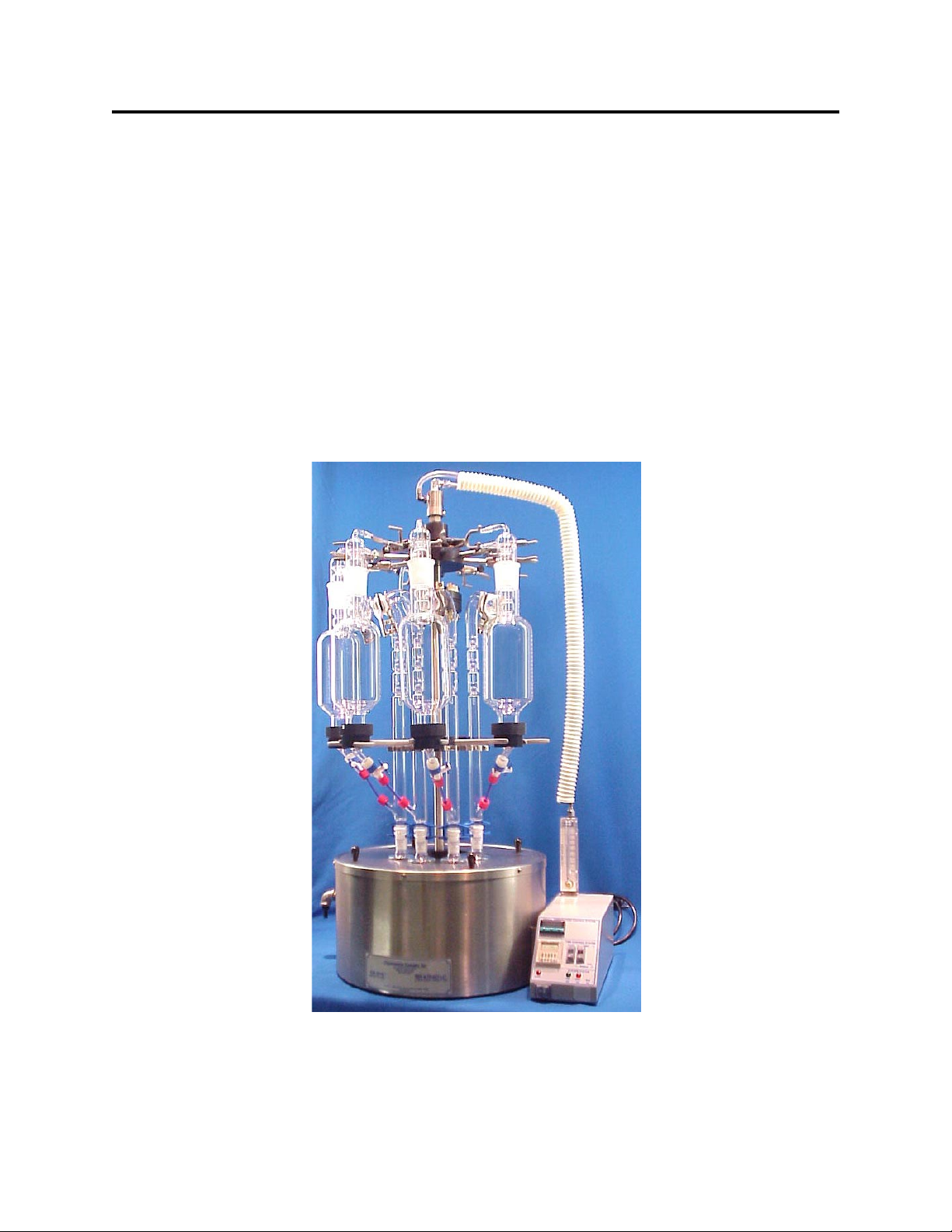
1 position Accelerated One-Step Extraction set, includes:
• GA3448: Ball joint clamp for J-Shaped Snyder column
• GA2273-A: Blue Delrin glassware clip for 24/40 joint, 2 piece adjustable
• GA2272-S: Nickel plated steel glassware clip for 19/22 joint
• GP3441: J-shaped 3-ball Snyder Column
• GP2243: Insulated Concentrator Tube 10ml, graduated
• GP3419: Cold Finger Condenser, 50x200mm, for 45/50 joint
• GP3442: Y-Shaped Drain cup and O-Ring
• GP3440: Extractor and Evaporator body, 1000 ml
• GP2240: Kuderna-Danish flask 100ml, for 19/22 (bottom) and 24/40 (top) joints
• GA3449: Membrane support screen, stainless steel
• GA3445: Membrane cup and plastic coupler
• GA2286-H: Thick wall FEP ribbed sleeve for 24/40 joints
• GA3447: Tubing, connectors, and FEP stopcock
GS3380
ROT-XTRACT-LCTM INTRODUCTION
Option Codes and additional items shipped
The following list contains option codes and items which may have been shipped in
conjunction with the standard parts shown on the previous pages. Please check your packing
list and order information carefully to determine if these items are included in your shipment.
Your shipment may contain the following optional items:
Option
-Z
-2
Description
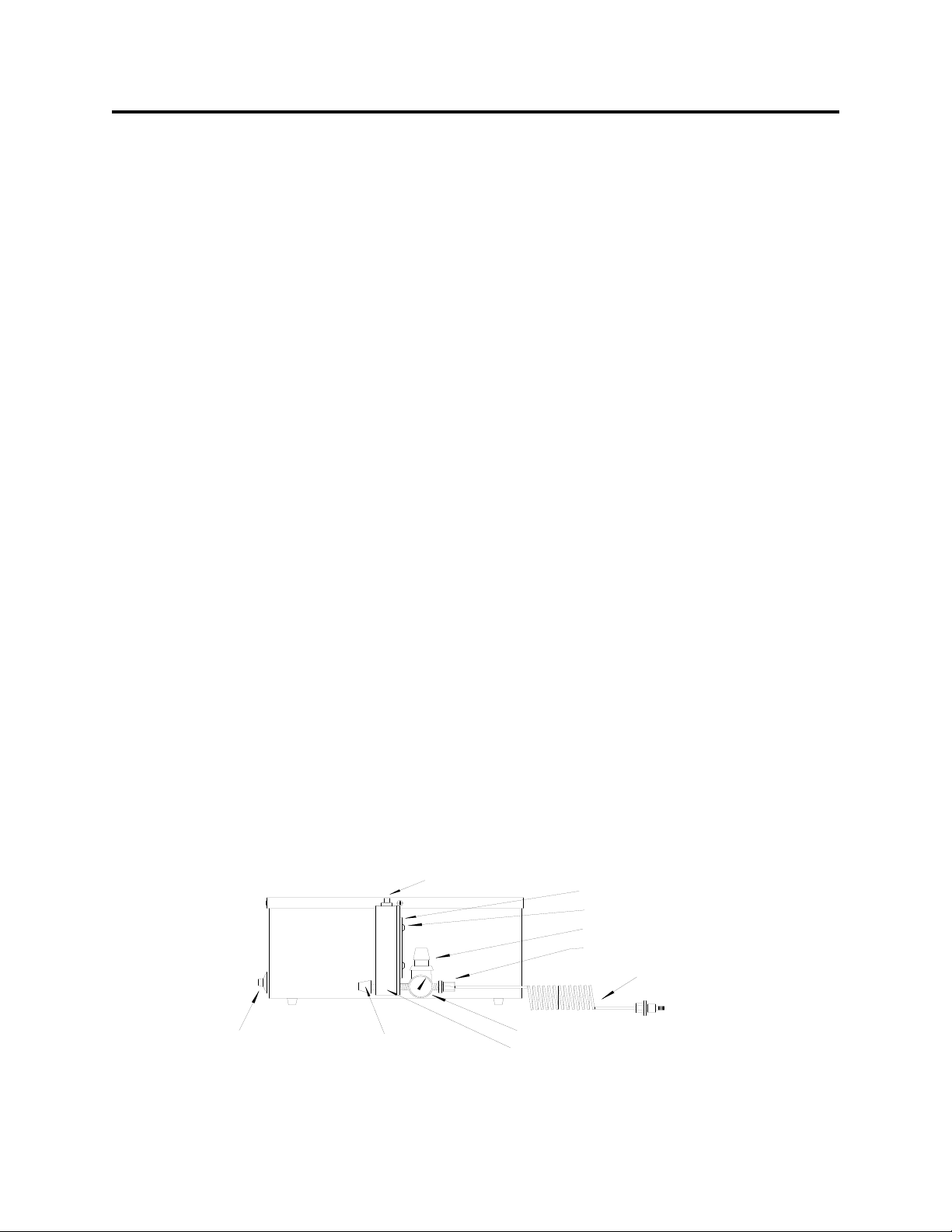
OA-SYS water bath has been modified for the Type-Z Purge Positive Pressure bath
option. Additional parts include: differential pressure gauge, mounting bracket, and
tubing.
OA-SYS water bath is wired as a 240 Volt unit.
V22.5 - 5 -

V22.5 - 6 -
INTRODUCTION
ROT-X-TRACT-LCTM
Instrument Description
The ROT-X-TRACT Solvent Extraction / Evaporation System is designed for general
evaporation and concentration of analytical or environmental samples to meet the needs of
specific methods under controlled and reproducible conditions.
The ROT-X-TRACT system features liquid / liquid extraction coupled with rapid
solvent evaporation with solvent vapor recovery. Solvent recoveries can exceed 90% by
volume under ideal conditions. The system may be used with cold tap water or a recirculating
chiller system. The digital controlled water bath provides even uniform heating without
scalding final samples. The parallel water manifold system provides even cooling water to
each of the eight condensers. The rotary water manifold allows unlimited instrument rotation
for front loading without condenser tubing wrapping about the instrument.
Figure 1

V22.5 - 7 -
INSTALLATION
ROT-X-TRACT-LCTM
Location
The ROT-X-TRACT evaporator system should be located on a bench top or in a
chemical fume hood if hazardous or flammable materials and solvents are to be used. The
location should provide the necessary support services for the instrument. These include
electrical power (required for water bath), cold water. Please review the Specifications Section
for further information.
Bath Setup
1. Position the bath on a stable flat surface such as a lab bench or in a chemical fume hood.
2. Turn the bath rocker switch to the “OFF” position.
3. Turn the heat switch to the center “OFF” position.
4. Plug the bath electrical cord into a 3 wire grounded electrical outlet rated for 110-120
VAC, 50-60 Hz, single phase, 15 amps.
Optional 220 VAC baths are clearly marked and should be plugged into a three wire
grounded electrical outlet rated for 220-240 VAC, 50-60 Hz, single phase, 15 amps.

V22.5 - 8 -
INSTALLATION
ROT-X-TRACT-LCTM
Bath Setup (Continued)
6. Type-Z Purge Positive Pressure Bath option - If you do not have this option, please
proceed to the next section. Procedures for operating this system may be found in
the Operation Section. Please refer to Figure 3 below for parts list and
installation.
A. Install the Type Z Purge Gauge Assembly to the rear of the bath as shown. The
bracket attaches to the rear of the bath and is held in place by a 6-32 x 1/4” screw
on the shoulder spacer and by a 1/4” bulkhead hex nut on the gas inlet fitting.
B. Connect the small white silicone tube attached to the gauge to the gas inlet fitting
using the compression nut provided.
C. Attach the filter with 5 foot tube to the plastic elbow fitting located at the base of
the bath or control box. Insert the filter into the fitting and tighten the nut.
Connect the tube to a clean gas source.
D. Test the system by turning on the gas flow to the Z Purge System. Adjust the
gas flow until the gauge reads 0.3 inches water pressure.
WARNING - If this unit is located in a hazardous area where volatile fumes are present,
the Z-Purge System must be activated for a minimum of 10 minutes prior
to activation of bath power. Please review the Safety and Operations
sections.
FIGURE 3
Gauge and Housing
1/4 White Silicone Tube
Tube Fitting Nut
3/8 OD Clear Tube
Bulkhead Hex Nut
Filter
Plastic Elbow Fitting
Flowmeter Bracket
Thermostat Knob
Shoulder Spacer
Gas Inlet Fitting
Front
Z-Purge Assembly Diagram - Side View
6/32 x 1/4 Screw
Side mount control box not shown here.

V22.5 - 9 -
INSTALLATION
ROT-X-TRACT-LCTM
Bath Setup (Continued)
7. Flow meter assembly - Provided with all ROT-X-TRACT Systems.
A. Units with control box
Attach the flow meter and bracket assembly onto the left rear corner of the
control box with the two 10/32 x 1/2” screws provided. The meter should be
positioned with the scale facing forward.
B. Connect the clear 1/4” ID x 3/8” OD tube to a cold water source (tap or chiller).
Source should be capable of producing 3.5 LPM (1 GPM) and being regulated to
30 psig maximum. If the source is in excess of 30 psig, then Organomation
part #XA0631 Pressure Reducing Regulator for water supply will be required.
The tube is connected to the lower fitting on the flow meter.
Figure 3

V22.5 - 10 -
INSTALLATION
ROT-X-TRACT-LCTM
Figure 4
Thermostat Knob
Front
Presure Reducing Regulator Diagram - Side View
Flowmeter Bracket
Pressure Regulator
Connector Tube Adapter Fitting
Connector Tube
Pressure Gauge
Flowmeter
Needle Valve
Gas Tube Adapter Fitting
6/32 x 1/4 Screw
Bath Setup (Continued)
8. Pressure Reducing Regulator Option - If you do not have this option, proceed to the next
section. When purchased with a ROT-X-TRACT System, this item is pre-installed onto
the flow meter, between the flow meter and the water inlet tube. Refer to Figure 4.
A. Remove the flow meter from the bracket.
B. Remove the water inlet Tube and fitting from the flow meter.
C. Connect the Pressure Reducing Regulator to the lower fitting on the back of the
flow meter. Position the regulator such that the adjustment knob is straight up
and the gauge points away from the bath.
D. Connect the water inlet tube to the regulator.
E. Re-connect the flow meter to the bracket.
F. The regulator may be adjusted by pushing the knob downwards and then rotating
the knob. The knob may be locked in position lifting it upwards.

V22.5 - 11 -
INSTALLATION
ROT-X-TRACT-LCTM
Instrument Setup
1. Place the instrument and stand into the water bath or on a flat level surface. The stand
is loose relative to the instrument and must be held in place while placing the assembly
into position.
2. Place the cover disk assembly onto the instrument. Slide the disk upwards 9” for 8.5”
deep baths and secure in place with the set screws in the disk collar.
3. Water services tube assembly
A. Connect the top of the water services tube assembly to the elbow fitting located
at the top of the instrument.
B. Connect the clear 3/8” ID tube at the top of the services tube assembly to the
black hose barb located at the top of the instrument. The spiral wrap prevents
the drain tube from collapsing at the bend.
C. Place the instrument into the water bath if not already installed.
D. Connect the lower SS tube of the services tube assembly to the top of the flow
meter located on the side of the bath or top of the control box.
E. Connect the drain tube at the bottom of the services tube to a suitable drain or
chiller system. Chiller systems purchased from Organomation have the proper
connection fittings provided, please reference the water chiller instructions for
proper chiller connections.
F. Once everything is in place and correctly positioned, tighten the SS nuts with a
wrench.

V22.5 - 12 -
INSTALLATION
ROT-X-TRACT-LCTM
Instrument Setup (Continued)
4. Cover Disk Adjustment – This item is pre-installed and need not be adjusted.
A. Install a single glass condenser into the condenser holder clamp located at the
top of the instrument.
B. Loosen the set screws in the cover disk collar so that the disk may be rotated.
C. Assemble a One-Step Extractor set. Rotate the cover disk until the glass
assembly can be placed vertically into position on the cover disk and connect to
the condenser.
D. Push the center tube downwards against the spring at the base of the stand a
distance of 6 mm (1/4”) and tighten the cover disk collar set screws. When the
center tube is released the cover disk should raise slightly. When fully loaded
with glassware, this will reduce drag on the bath rim and allow the instrument to
rotate more freely.
5. Place the hole covers onto the cover disk. They should be used whenever a glass set is
not present in a position.
6. Remove all glassware from the system, if present.
7. Fill the bath with water.

V22.5 - 13 -
INSTALLATION
ROT-X-TRACT-LCTM
Glassware setup
Note: Glassware manufactured by other sources may not fit or work correctly in the ROT-X-
TRACT system. Care and caution should be exercised relative to these instructions and in
operation of non Organomation glassware in the ROT-X-TRACT system.
1. Condenser Glassware Setup Procedures – The following procedures cover setup and
installation of Organomation glassware in the ROT-X-TRACT instrument.
A. Install the white silicone water tubes with quick connect fittings onto the glass
hose barbs on the condensers (two per condenser) secure with zip ties to ensure
the tubes do not pop off. When elbow QD’s are present, they should face each
other when installed.
B. Install each condenser in sequence around the water manifold. Condensers may
be installed by placing the condenser in the upper most three prong clamp with
the water tubes facing inwards.
C. Connect the water tubes on each condenser to the manifold. For optimal
position, connect each fitting on the water tube to the fitting on the manifold
which is three fittings to the left of the closest fitting to the condenser. Each
condenser will have one water tube connected to the upper and lower manifold.
2. Place the bottom half of the plastic coupler into a ring clamp located on the instrument.
This will act as a holder during assembly.
3. Attach the PTFE valve to the bottom of the Y-Cup as follows:
A. Remove the split nut from the Teflon valve.
B. Slide the split nut over the lower end of the Y-Cup.
C. Slide the blunt end of the Teflon valve into the lower end of the Y-Cup as far as
it will go. It is installed correctly when the white split nut will screw fully into
the blue nut on the Teflon valve. Screw the nuts together.
4. Place a Y-Cup with O-Ring (positioned under lip) into the separated plastic coupler.
5. Place the ceramic ring on top of the Y-Cup.
6. Place a hydrophobic membrane (sold separately) on top of the membrane screen.
7. Place the top half of the plastic coupler over the lower lip of the one liter extractor,
it will be loose.

V22.5 - 14 -
INSTALLATION
ROT-X-TRACT-LCTM
Glassware setup (Continued)
8. Carefully position the extractor onto the Y-Cup membrane assembly in the instrument.
When positioned, the plastic coupler halves may be screwed together until snug (do not
tighten fully at this point).
9. Rotate the extractor and Y-Cup assembly until the lower portion of the Y-Cup is in line
with the upper arm of the extractor.
10. Place an elongated boiling chip (sold separately – OAI Cat # GA2245) into the
concentrator tube.
11. Connect a 10 ML concentrator tube to the bottom of the Inline KD. Secure in place
with the 19/22 clip.
12. Place the 24/40 rigid PTFE sleeve into the top of the Inline KD.
13. Connect the snyder column into the top of the inline KD. Secure together using the
24/40 adjustable clip.
14. Place the snyder column / KD assembly into the instrument. The lip on the KD will
rest on the cover disk. The snyder column will clip to the lower clamp ring. The clip is
strong enough to hold the glassware in place when not connected to the extractor.
15. Connect the upper snyder column ball joint to the upper side on the extractor.
Secure in place using the 35/25 ball clamp.
16. Connect the short 1/4” tube between the snyder column and the valve. Secure
in place with the red screw caps. The septum within the cap has a PTFE face on one
side. The septum is correctly installed with the PTFE face against the glass
surface.
17. Place the condenser into the top of the extractor.

N96.0
INSTALLATION
ROT-X-TRACT-LCTM
V22.5 - 15 -
Instrument Controls – Analog Water Bath System
Toggle Switch - Located on the front right bath label. Turns power to the bath on
and off.
Thermostat Knob - Located on the front center bath label. Adjusts the bath
temperature.
Amber Light - Located on the front left bath label. Indicates heating when
heaters are energized, will cycle at temperature.
Instrument Controls - Digital Control Box System
Digital Controller - Controls bath temperature
Timer Controller - Controls timed functions when selected. Used for bath preheat
or automated control of services.
Time Switch - Starts or resets timed operation, momentary switch.
Heat Switch - Selects manual or timed control of heat system.
Time Light - Green, indicates timed operation in progress.
Alert Light - Red, indicates timed operation complete or inactive.
Heat Light - Amber, indicates heat system is active.

V22.5 - 16 -
SAFETY
ROT-X-TRACT-LCTM
Safety Considerations
READ THIS SECTION BEFORE EQUIPMENT OPERATION!
This equipment is designed for use in the Analytical or Environmental Laboratory by trained
laboratory personnel for evaporative applications. Use of this equipment beyond its stated
intended purpose and operating parameters is not recommended and will be the sole
responsibility of the user. This equipment should not be modified or altered. Organomation
Associates, Inc. assumes no liability for any misuse of or modification to this product and such
misuse or modification will immediately void all warranties.
This equipment should be used in accordance with the operating instructions contained in this
manual. For alternative uses not covered in this manual, please contact Organomation
Associates technical department for product suitability, safety, and alternative operating
instructions.
The following are general safety guidelines recommended when using this product. Please
consult your laboratory safety officer for any additional safety steps which may be necessary
for your specific application or material.
1. Thoroughly review your MSDS (Material Safety Data Sheets) for all chemicals to be
used with this equipment.
2. Do not use this equipment with materials with auto ignition points below 150 ºC.
3. Hand and eye protection are required when using this product. Additional protection
may be required with respect to the materials being used. Please consult your labora-
tory safety officer.
4. This product should only be used in a chemical fume hood with adequate ventilation.
5. Do not move the product when hot. Scalding from bath water may result.
6. Do not open bath enclosure while energized - SHOCK HAZARD!
7. Repairs of electrical components should be conducted by a trained electrical technician.
Incorrect replacement parts or assembly may damage the product and create a serious
safety hazard for the user. Factory repair is recommended.
8. Highly flammable materials such as petroleum ether should not be used with this
product unless the Type-Z Purge positive pressure bath option is installed and operating.
9. Use of acidic or base materials may damage this product and are not recommended
unless the product was ordered with the optional protective coating in PTFE.

V22.5 - 17 -
OPERATION
ROT-X-TRACT-LCTM
Planning and Preparation
It is important to thoroughly understand the procedures and equipment operation prior to
the use of the equipment. High speed solvent extraction and evaporation requires a balance of
sample volume, bath temperature, cooling water, correct setup, and adjustment. Improper use
can impair performance, contaminate samples, or result in sample loss. Environmental and
operating conditions are also important, examples include use of water or oil based heating
media, hood airborne contaminates, glass cleaning techniques, and sample handling procedures.
If you are unfamiliar with the use of the ROT-X-TRACT System or are working with a new
procedure, it is recommended that a trial run be made using a sample blank to determine
optimal operating conditions.
The ROT-X-TRACT System is designed to handle multiple samples simultaneously up to the
capacity of the equipment (8 positions).
CAUTION!!!
Samples containing ether based, fuel, munitions, or other extremely flammable or
explosive materials, compounds, or residues should not be used in this equipment unless
the heating unit is equipped with the TYPE -Z Purged Positive Pressure Bath Option.
Even equipped with this option, either passive or active, extreme care and caution must be
exercised when using these materials. The equipment must be placed in a location with
adequate ventilation and safe guards, recommendations include fire suppression system, shatter
proof glass, and adequate shielding for personnel. No other electronic devices should in the
same location unless they are either Z-Purge protected or are explosion proof. No flammable
solvents should be stored in this location. Materials capable of forming peroxides prior to or
during evaporation must be stabilized with sufficient anti-oxidant or they should not be used.
Under no circumstances should this equipment be used with materials capable of auto
ignition below 150 Degrees Centigrade including materials containing peroxides.
Please Contact Organomation Associates Technical Support if you have any questions
concerning the use of TYPE-Z Purged equipment or questionable materials in OAI
equipment.

V22.5 - 18 -
OPERATION
ROT-X-TRACT-LCTM
Bath Operation
1. Press the reset button on the GFCI (if present).
2. Check bath water level, fill if necessary.
Digital Control Box Systems
1. Turn the bath rocker switch on.
2. Digital Electronic Control - Adjust the digital controller to the desired temperature set
point.
The controller set point may be adjusted by depressing the “*” on the front panel and
depressing the up or down arrow keys to the desired temperature. Release the “*” key
when the temperature desired is shown on the display. This setting will be retained
even after the system is turned off.
To view the current set point, depress and hold the “*” key. Release when done.
Note: The controller set point can be set above the maximum heating capability of the
bath it is mounted in. Doing so will cause the bath to operate continually at
100% heat without temperature control. This type of operation defeats the
purpose of the controller, may cause a safety problem, and is not recommended.
Water bath maximum temperature 100 ºC.
3. Manual Heat Control
A) To operate the heat system manually, depress the heat switch to the lower posi
tion. The Amber heat light will glow indicating the heat system is active.
Temperature will be controlled by the digital temperature controller.
B) To turn off the heat service, simply return the switch to the middle “OFF”
position.

V22.5 - 19 -
OPERATION
ROT-X-TRACT-LCTM
Bath Operation (Digital Control Box Systems – Continued)
4. Timed Heat Control
The time control system allows several operating modes which can be set for different
operations. The timer may be used to preheat the bath in the morning prior to use, to shut
down the system after a specific period of time (unattended operation), or for non- dry
ness endpoint operations.
Preheat Bath Timed Operation
To begin heating the bath automatically prior to use the following morning, please follow
the procedures below.
A) Fill the bath with water to within 0.5 inches of the bath rim or up to the overflow
port if so equipped.
B) Turn the bath on.
C) Hold the MODE button until menu screen appears.
D) Screen to read “out.n” to select output operation mode, use directional arrows
to select program “ond.1” (On Delay). Hit MODE once to continue to select
time range.
E) Select time range under “t.rnG”, use directional arrows to determine the
desired range using h (hour), m (minute), s (second).
Hold MODE to return to standby.
Other menu options are not vital to the Preheat Bath process.
F) In standby, calculate the amount of time that will elapse from the point the bath will
be left until it will be needed the following day less 1 hour for heat up time.
Example: You leave at 5:30 PM and plan to arrive at 7:00 AM and want the
bath heated and ready to go.
Elapsed time is 13.5 hours less 1 hour for heating leaves 12.5
hours.
Use directional arrows to set desired time, for this example: 12h30m.
Hit MODE once to confirm time.
G) Set the heat switch to timed operation.
H) Set the gas switch to the middle position (OFF).
I) Press the start switch to begin the timed countdown operation. At the
completion of the operation the bath heat will be turned on automatically.

V22.5 - 20 -
OPERATION
ROT-X-TRACT-LCTM
Bath Operation (Digital Control Box Systems – Continued)
Automatic shutdown of heat services - unattended operation
To shut down the bath services after a period of time during a sample evaporative run,
ideal when each sample is to be taken to dryness and the operator will not be present at
the completion of the run. Please follow the procedures below.
A) Hold the MODE button to enter menu screen.
B) Screen to read “out.n” to select output operation mode, use directional arrows
to select program “ofd” (Off Delay). Hit MODE once to continue to select
time range.
C) Select time range under “t.rnG”, use directional arrows to determine the de
sired range using h (hour), m (minute), s (second).
Hold MODE to return to standby.
Other menu options are not vital to the Preheat Bath process.
D) In standby, use directional arrows to set time that is most ideal for the period
necessary to process the sample.
Example: You wish to process 8 samples. Experience has shown that this takes
approximately 5 hours to complete. It is already 3 PM and you
expect to leave before 6. Use the automatic time system to shut off
the bath heat after you leave:
Evaporation time is 5 hours plus 30 minutes for variance, this
gives 5.5 hours. Set the timer as follows: 5h30m
Hit MODE once to confirm time when set.
E) Set the heat switch to timed operation or manual to bypass timed control.
F) Press the start switch to begin the timed countdown operation. At the
completion of the operation the gas flow will be turned off automatically.
NOTE: To stop a timed run at any point simply push the reset switch.
Table of contents
Other Organomation Associates Laboratory Equipment manuals
Popular Laboratory Equipment manuals by other brands

BIO RAD
BIO RAD QX200 instruction manual

PHYWE
PHYWE 11207-30 quick start guide

Endress+Hauser
Endress+Hauser Liquistation CSF39 operating instructions

Millipore Sigma
Millipore Sigma SNAP i.d. 2.0 user guide

Showa Denko
Showa Denko Shodex IC SI-90 4E Operation manual

Caliper Life Sciences
Caliper Life Sciences Twister II user manual