- 4 -
GB
TABLE OF CONTENTS
0800_GB-Inhalt_1612
Recommendations
for work safety
All points refering
to safety in this
manual are
indicated by this
sign.
Table of contents
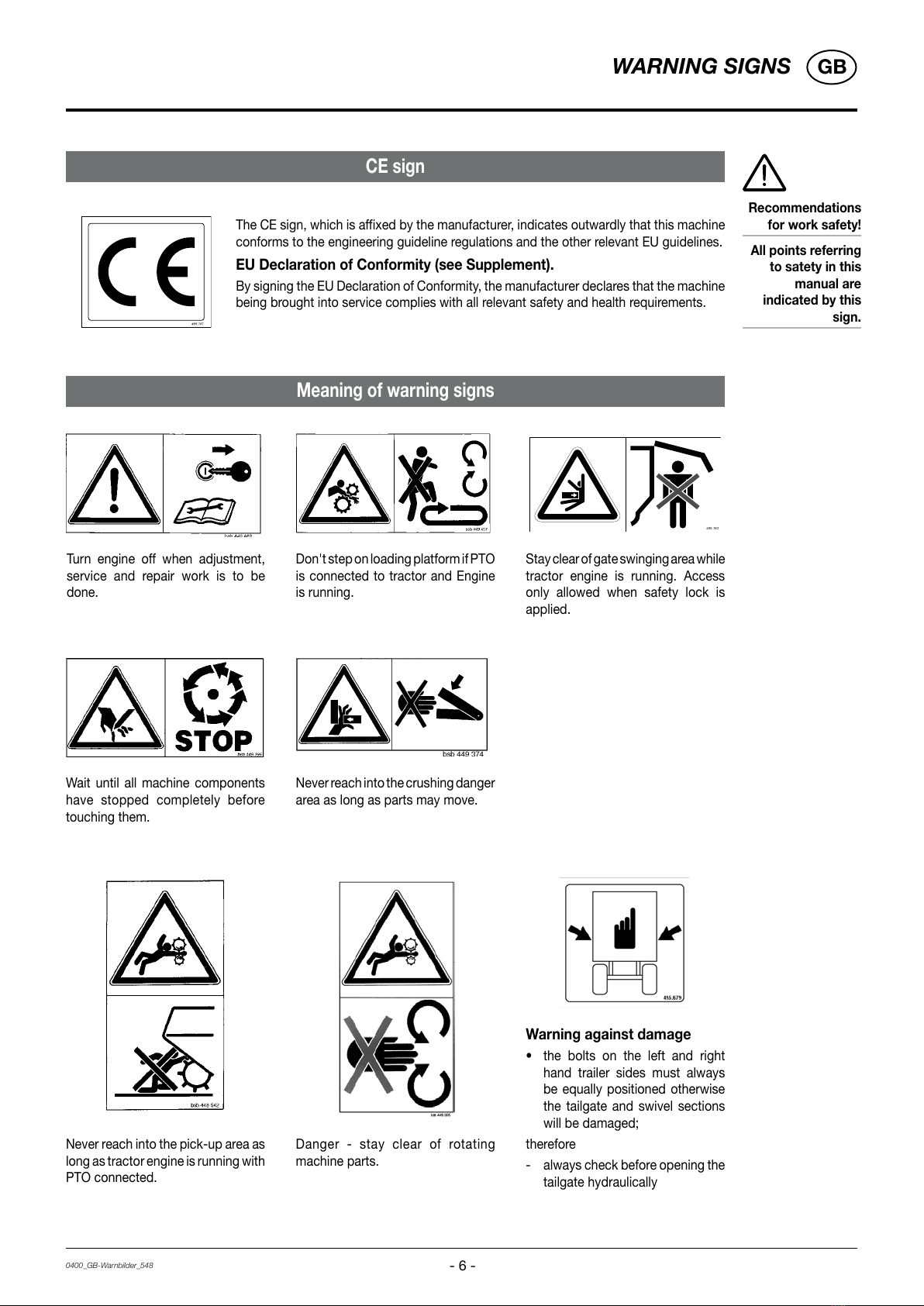
WARNING SIGNS
CE sign ..................................................................... 6
Meaning of warning signs......................................... 6
PUTTING INTO OPERATION
General safety tips for using the trailer..................... 7
Before starting work ................................................. 8
FIRST-TIME CONNECTION TO TRACTOR
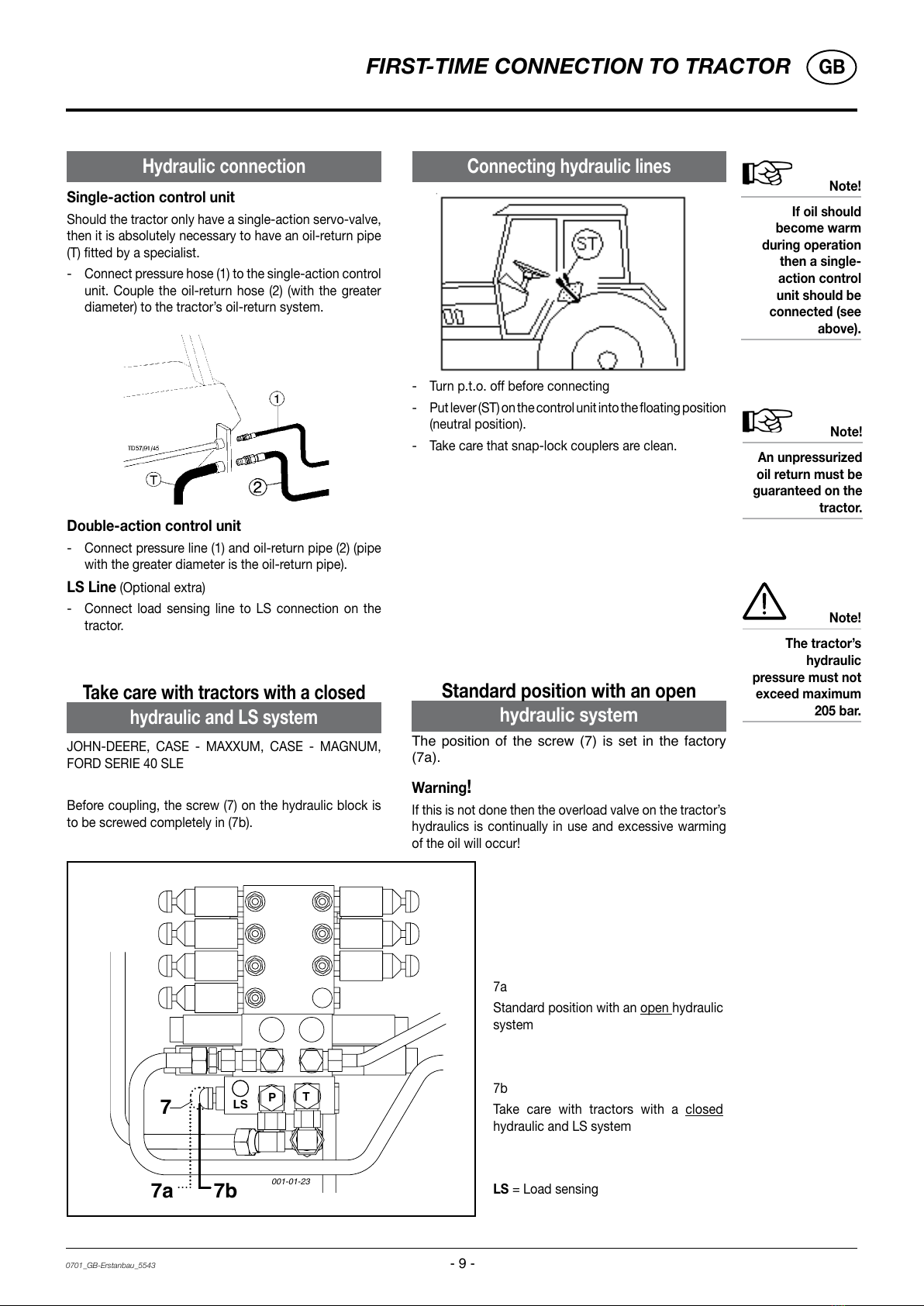
Hydraulic connection................................................ 9
Connecting hydraulic lines ....................................... 9
To make the connection to the tractor ................... 10
Adjusting the hose container.................................. 10
Adjusting the trailer coupling ................................. 11
Vibration absorption 1) ............................................ 11
Setting the pivoting drawbar .................................. 11
Locking the trailing front axle ................................. 12
Adjusting the drawbar ............................................ 13
Mounting the DST 2000 type forked drawbar ........ 13
Traction coupling ball.............................................. 13
SUPPORTING WHEEL
Raising the jack stand by hand .............................. 14
Garaging the trailer................................................. 14
PICK-UP
Setting of Pick-up pivoting area............................. 15
Setting the Pick-up load alleviation........................ 15
CUTTING UNIT, CUTTER BEAM
Cutting Unit............................................................. 16
External cutting unit buttons .................................. 16
Swinging the cutter beam....................................... 17
Adjusting the cutter beam ...................................... 18
Adjusting the cutters............................................... 18
Checking the clearance from the blades to the press
rotor ........................................................................ 19
TAILGATE
Safety mechanism ................................................. 20
Unloading using dispensing rollers......................... 20
Removal of regulating rollers .................................. 21
REGULATING ROLLERS
Scraper floor switch................................................ 22
Installing an oil pressure switch.............................. 22
TOP FRAME SECTION
Assembling the top frame section.......................... 23
DIRECT CONTROL - OPERATION
"DIRECT CONTROL" operating unit....................... 24
Carry out required hydraulic function ..................... 24
Loading functions ................................................... 25
Unloading functions................................................ 26
Pivoting drawbar / Forage top frame...................... 26
Automatic Loader- unloader 3) ............................... 27
Switching on automatic loader............................... 27
Switching on automatic unloader........................... 27
POWER CONTROL - OPERATION
Configuration .......................................................... 28
Control panel .......................................................... 28
Button indication .................................................... 28
Power control initial operation................................ 29
WORK Menu loading functions .............................. 29
WORK menu unloading functions .......................... 31
SET functions ......................................................... 34
Diagnostic functions............................................... 36
Cutting unit monitoring........................................... 36
Sensor test ............................................................. 37
Adjusting machines ................................................ 37
Wireless Power Control - Control........................... 38
Charging the AC ..................................................... 38
AC discharge .......................................................... 39
Radio contact range ............................................... 39
Pairing..................................................................... 39
ISOBUS - TERMINAL
Operation ISO-terminal........................................... 41
Start menu .............................................................. 42
Base setting menu.................................................. 42
Loading menu......................................................... 42
Unloading menu ..................................................... 43
Unloading menu ..................................................... 44
Data menu .............................................................. 45
Config-menu........................................................... 45
Set menu ................................................................ 46
TEST menu ............................................................. 47
Diagnostic menu.................................................. 48
Joystick - Loader wagon configuration.................. 49
Setting the Joystick ................................................ 49
Uses of tractor data................................................ 50
LOADING THE TRAILER
Loading process in general .................................... 51
Adjusting the pick-up ............................................. 51
Starting the loading process................................... 51
To observe during the loading process! ................. 51
UNLOADING
Unloading the trailer ............................................... 52
Regulating equipment shut-off clutch (NS) ............ 52
Finishing the unloading process............................. 52
MAINTENANCE
Safety point ............................................................ 53
General maintenance hints..................................... 53
Cleaning of machine parts...................................... 53
Parking in the ope................................................... 53
Winter storage ........................................................ 53
Drive shafts............................................................. 53
Hydraulic unit.......................................................... 53
Safety points........................................................... 54
Gas container ......................................................... 54
Overload clutch ...................................................... 54
Brake adjustment ................................................... 54
Opening the side protectors................................... 54
Pick-up ................................................................... 55
Press....................................................................... 56
Once a year ............................................................ 56
Cutting unit ............................................................. 57
Removing a stripper ............................................... 58
Transmission........................................................... 59
Chains..................................................................... 59
Oil pressure switch ................................................. 60
Safeguarding the electrical unit.............................. 60
Changing the filter .................................................. 60
Maintaining electronic parts ................................... 61
Adjusting measurement for end switch.................. 61
Connecting the brake hoses .................................. 62
Service and maintenance on the air brake unit ...... 62
Release position on the brake unit ......................... 63
Parking the wagon.................................................. 63