GB
TABLE OF CONTENTS
- 4 -
271.GB.809.0 INHALT
Table of contents
Meaning of warning signs.................................................................................................................................................................4
Hitching.............................................................................................................................................................................................5
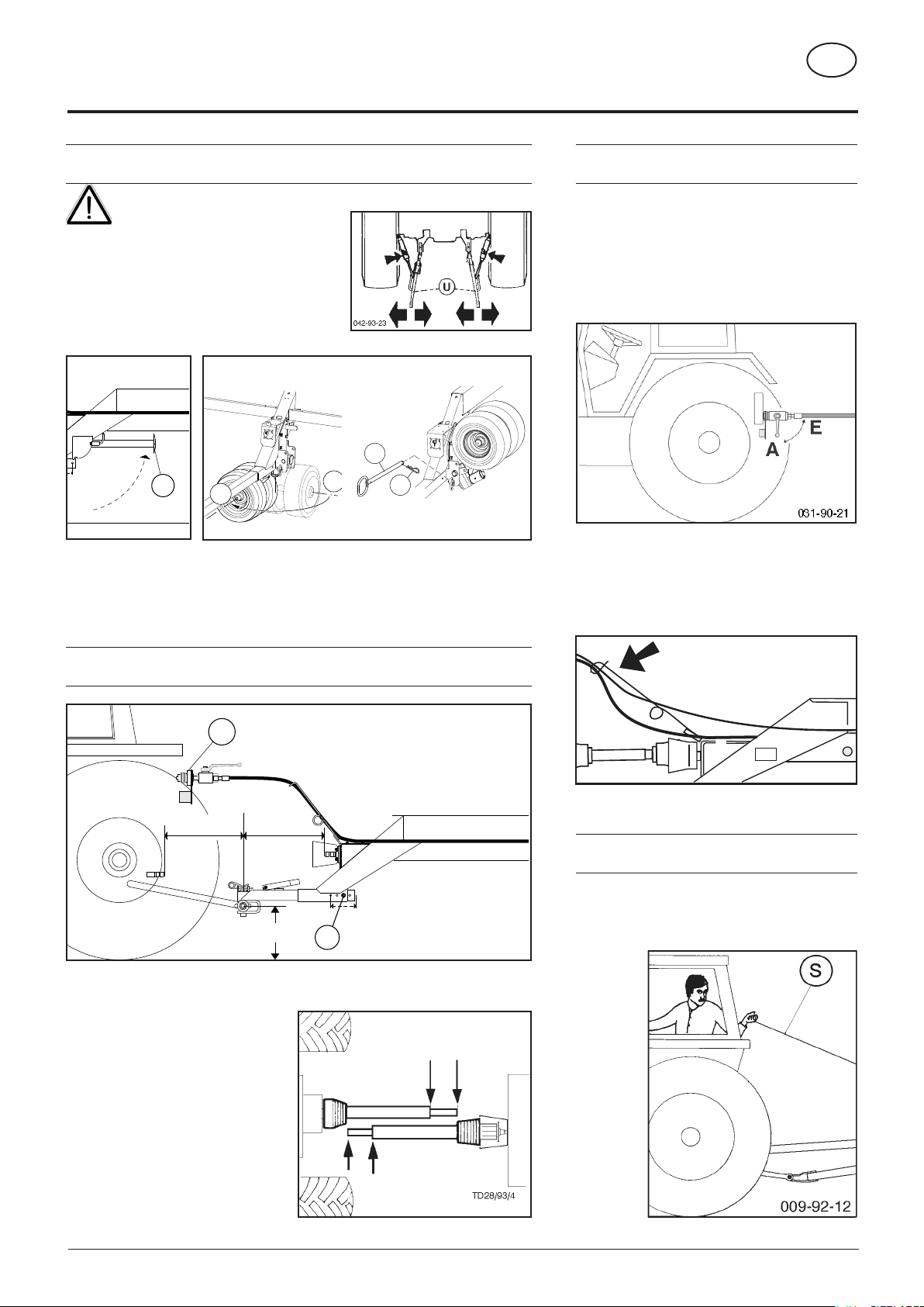
First-time connection to tractor.........................................................................................................................................................5
Hydraulic connection ........................................................................................................................................................................5
Release rope ....................................................................................................................................................................................5
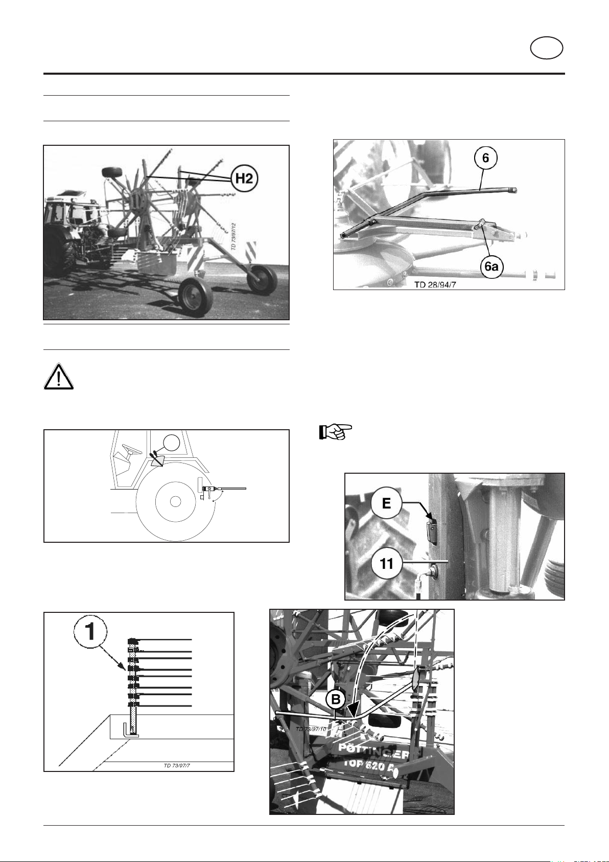
Lowering the machine ......................................................................................................................................................................6
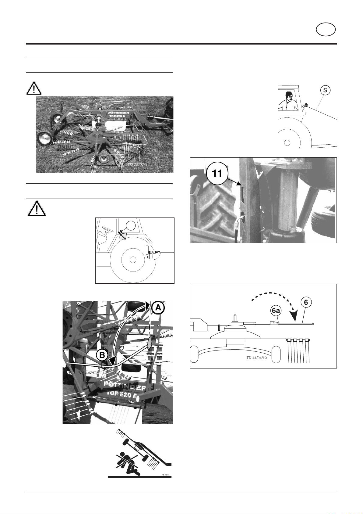
Driving on public roads.....................................................................................................................................................................6
Driving on public roads.....................................................................................................................................................................7
Conversion from working to transport position .................................................................................................................................7
Operating position ............................................................................................................................................................................8
Conversion from transport to working position .................................................................................................................................8
Preparing for operation.....................................................................................................................................................................9
Conversion to single rotor operation (border areas).........................................................................................................................9
Swather with „MULTITAST“ system ...............................................................................................................................................10
General guidelines for working with the machine...........................................................................................................................12
Safety hints.....................................................................................................................................................................................12
P.t.o. speed.....................................................................................................................................................................................12
Turning manœuvre in working position .........................................................................................................................................12
Take care when turning on slopes!.................................................................................................................................................13
working on slopes ..........................................................................................................................................................................13
Safety points...................................................................................................................................................................................14
General maintenance hints.............................................................................................................................................................14
Cleaning of machine parts..............................................................................................................................................................14
MAINTENANCE .............................................................................................................................................................................14
Parking in the open.........................................................................................................................................................................14
Winter storage ................................................................................................................................................................................14
Drive shafts.....................................................................................................................................................................................14
Hydraulic unit..................................................................................................................................................................................14
Transmission ..................................................................................................................................................................................15
Lubrication chart.............................................................................................................................................................................15
Technical Data................................................................................................................................................................................16
Position of Vehicle Identification Plate............................................................................................................................................16
Defined use of the Rotary Swather.................................................................................................................................................16
Optional equipment ........................................................................................................................................................................16
Supplement ....................................................................................................................................................................................17
Recommendations for work safety ................................................................................................................................................19
DRIVESHAFT.................................................................................................................................................................................20
Important! Additional Information....................................................................................................................................................23
Combination of tractor and mounted implement.............................................................................................................................23
CE sign
The CE sign, which is affixed by the manufacturer, indicates outwardly that this machine conforms to the engineering
guideline regulations and the other relevant EU guidelines.
EU Declaration of Conformit By signing the EU Declaration of Conformity, the manufacturer declares that the
machine being brought into service complies with all relevant safety and health requirements.
Meaning of warning signs
Do not enter rotor area while driving motor
is running.
Never reach into the crushing danger area as
long as parts may move.
Stay clear of swinging area of implements
495.173