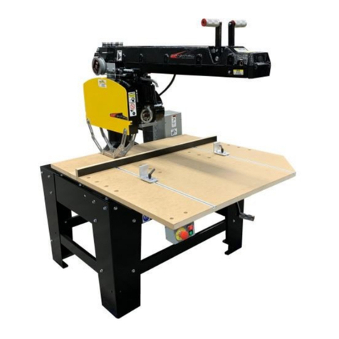
Original Saw Company 3551 Manual

1
This manual is provided for your convenience in the use
and care of your saw. These instructions include opera-
tion, precautions, preventative maintenance and other
pertinent data to assist you in assuring long life and de-
pendable service from your saw.
WARNING: FOR YOUR SAFETY READ AND UNDERSTAND THIS MANUAL
PRIOR TO USING THE SAW. REVIEW ALL SAFETY RULES AND OPERATING
INSTRUCTIONS FREQUENTLY.
RADIAL ARM SAW
TYPE 10 - cross cut only
16” models 3551, 3556, 3571, 3576
For Serial number 20190603790 forward
(March 2020)
Operations & Maintenance Manual
Original Saw Company
465 Third Ave SE
Britt, IA 50423 USA
PH 641-843-3868
800-733-4063
customerservice@originalsaw.com
www.originalsaw.com
Getting Started
Unpacking, general machine precautions, wiring,
installation

2
Service Record
Serial Number_____________________ Date Purchased ______________
Date Service Performed By

3
TABLE OF CONTENTS
SECTION PAGE
Service Record ……………………………………………………………………………. 2
Warranty Information ……………………………………………………………………… 3
Power Tool Safety ……………………………………………………………….………… 4-5
Preventative Maintenance …………………………………………………………….. 5- 6
Symbols / Decals ………………………………………………………………………….. 7
Decal Locations ……………………………………………………………………………. 8
Saw Components and Controls ……………………………………………………..…… 9
Product Specifications …………………………………………………………………....10-12
ANSI Conformance ………………………………………………………………….…….. 13
Saw Assembly and Installation …………………………………………………....……..14-18
Electrical Connections ………………………………………………………….... 14-17,30-31
Arbor Rotation ……………………………………………………………....……….…… 15
Changing Motor Voltage …………………………………………………….………... 15, 30
Operating Instructions ………………………………………………………………...….19- 23
Blade Mounting ……………………………………………………………………………. 18
Alignment and Adjustments ………………………………………………………….. 24-29
Parts Diagram and Listings …………………………………………………………..... 26-35
Troubleshooting …………………………………………………………………….… 32-34
Industrial Use Warranty Information
Your new Original Radial Arm Saw is precision manufactured under strict quality standards. In the un-
likely event there is trouble with your machine, the Original Saw Company warrants the machine for the
period of one year from the date of purchase. The warranty covers defects in materials and workman-
ship. We will cover the cost of the defective part and ground shipping. If a replacement part is sent
under warranty the defective part must be returned to Original Saw Company or you will be charged for
the replacement. The part must also be accompanied by a return goods authorization number. This
number can be obtained by calling customer service at 1-800-733-4063. When the part is returned it
may be repaired or replaced at our discretion. The part must be shipped prepaid to: The Original Saw
Company, Attn. Warranty Replacement Counter, 465 Third Avenue SE, Britt, Iowa 50423.

4
GENERAL RULES FOR SAFE OPERATION OF POWER TOOLS
1. KNOW YOUR POWER TOOL. Read the owner’s manual carefully. Learn the applications and
limitations as well as the specific potential hazards of the tool.
2. GROUND ALL TOOLS.
3. KEEP GUARDS IN PLACE. Keep guards in working order.
4. KEEP WORK AREA CLEAN. Cluttered areas and benches invite accidents.
5. AVOID DANGEROUS ENVIRONMENTS. Don’t use power tools in damp or wet locations. Keep
work area well lit.
6. KEEP CHILDREN AWAY. All visitors should keep a safe distance from the work area.
7. DON’T FORCE TOOL. The tool will do a better job if used at its designed rate.
8. WEAR PROPER APPAREL. Loose clothing, gloves or jewelry may get caught in moving parts.
Rubber footwear is recommended when working outdoors.
9. USE PROTECTIVE GLASSES. If operation is dusty also wear a dust mask.
10. DON’T OVER REACH. Keep proper balance and footing at all times.
11. MAINTAIN TOOLS WITH CARE. Tools kept sharp and clean provide the best and safest
performance. Follow instructions for lubricating and changing accessories.
12. DISCONNECT TOOLS FROM POWER SOURCE. When not in use, before servicing, when changing
accessories, blades, or cutters, the tool should be disconnected and locked out.
13. REMOVE ADJUSTING KEYS AND WRENCHES. Make it a habit to ensure keys and adjusting
wrenches are removed prior to starting tool.
14. USE RECOMMENDED ACCESSORIES. Consult your distributor or Original Saw Company for
recommended accessories. Using improper accessories may cause hazards.
15. SECURE YOUR WORK. Use clamps or a vise to hold work when practical.
16. NEVER LEAVE TOOL RUNNING WHILE UNATTENDED.
17. ONE OPERATOR ONLY. The person who operates the saw should also position the work.
18. DO NOT REMOVE SMALL SCRAPS FROM THE TABLE WITH YOUR FINGERS.
POWER TOOL SAFETY
CAUTION
ALL GUARDS MUST REMAIN IN PLACE FOR SAFE CUTTING OPERATON.
NOTE:
This manual is not totally comprehensive. It does not and
cannot cover every possible safety and operational factor
which may arise during the life of the machine.

5
Modifications:
− • Any modifications to the machine including in-
corporation into an assembly, addition of integrat-
ed feeds or other changes are the responsibility of
the end user and the end user must ensure ongo-
ing compliance.
Additional Safety Actions to be Take by End
User
− • Lock out Tag out procedures to be adopted dur-
ing all maintenance.
− • Lock out Tag out procedures to be observed
when changing blade
Functional Testing
− • Braked run down times test—tested monthly
(30 second brake run down )
− • Upper Guard locking—tested monthly, prove
there is an inability to open upper guard without
tools.
− • Test lower guards for hang ups make sure upper
plastic section drop down to cover blade
− • Test lower ring guard (inner) test to make sure it
moves freely, it is not bent, and does not hang up–
must drop freely to lower portion of blade
Instructions for Use:
− • Always observe the safety instructions and
applicable regulations.
− • Ensure the material to be sawn is firmly secured
in place.
− • Apply only a gentle pressure to the tool and do
not exert side pressure on the saw blade.
− • Avoid overloading.
− • Install the appropriate saw blade.
− • Do not use excessively worn blades.
− • The maximum rotation speed of the tool must
not exceed that of the saw blade.
− • Do not attempt to cut excessively small pieces.
− • Allow the blade to cut freely. Do not force.
− • Allow the motor to reach full speed before
cutting.
− • Make sure all locking knobs and clamp handles
are tight.
− • Never run the machine without the guards in
place.
− • Never lift the machine by the table top.
Preventative Maintenance
Original Radial Arm Saws are designed to provide
you with precision cutting with a minimal amount
of maintenance. The frequency of the mainte-
nance depends on the amount of use and the
desired cutting quality.
Always disconnect and lockout power supply
before performing maintenance.
Daily
− • Wipe down the machined tracks in the arm,
this will prevent wood pitch buildup on the
machined surfaces
− • Dust off and remove excess saw dust
Monthly
− • Repeat daily tasks but use denatured alco-
hol or paint thinner to wipe down tracks
− • Remove arbor nut, collars, and saw blade.
Inspect the saw blade teeth for sharpness
and broken tips. Replace or re-sharpen as
necessary
− • Remove end cap and remove carriage and
rest on the table (do not remove wiring) then
wipe off the bearings with denatured alcohol
or paint thinner to remove all wood pitch
buildup, DO NOT lubricate the tracks this will
case premature track wear due to sawdust
sticking to the tracks.
− • Inspect arbor, are the arbor bearings still
tight and free of play? If not then they will
need to be replaced by a technician or at a
electric motor shop.
− • Inspect all wiring to check for cracks, re-
place if worn or cracked.
− • Using compress air blow out the cooling
ducts in the motor by blowing through from
the arbor side of the motor to the back o the
motor, (use Personal Protection equipment ie
safety glasses and a face mask to protect
from the dust)
− • Dust off all surfaces using a vacuum remove
all saw dust from the table and the frame.

6
MANTAINENANCE RECORDS
Preventative Maintenance … Continued
− • After many years of use your saw may need
replacement parts. If any of the following
wears out all others listed should be checked
also.
− • Roller head bearings: Check for free, smooth
rotation. Do not attempt to lubricate.
− • Arm Tracks: If the saw is used primarily for
short cut-offs, the tracks may wear making it
difficult to adjust the roller head bearing for full
length arm travel. Arms can generally be re-
machined—contact Original Saw for pricing
and shipping instructions.
− • Motor bearings: Check for free, smooth rota-
tion. Do not attempt to lubricate.
− • Elevating mechanism: Remove, clean and
lubricate with type EP grease. Check for wear
between nut and jack screw. Replace assem-
bly if loose.
Use this space to record service or use
page 2 for a more detailed recording for
your Original radial arm saw.

7
SYMBOLS / DECALS
Always replace damaged, missing, or illegible decals.
Contact Original Saw at 641.843.3868 for replacement
parts.
6
.Denotes hearing and eye
protection required.
7
.Denotes guards required to be
in place.
8
.
Denotes general safety hazard.
See operators manual for more
information pertaining to these
areas.
9
.Denotes lift point.
Denotes risk of injury, loss of life,
or
damage to the tool in case of not
observing the instructions in this
manual.
1
.
Denotes risk of electrical shock.
2
.
Denotes risk of pinching hazard.
3
.
Denotes hazard of rotating
blade.
4
.
Denotes hazard of entangle-
ment.
5
.

8
SYMBOLS / DECALS
Guard:
Index # 4 Hazzard Rotating blade
# 6 Hearing and eye protection
# 7 Guards required to be in place
- Do Not rip or plough from this
end
- rotation direction
- use blades rated at 3600 rpm
Arm:
- General Caution
Frame:
Index # 9 Denotes lift point
Note there are 2 on front of frame
and 2 on the rear of the frame
Danger
# 2 Hazardous
Voltage
ARM:
- Caution , do no operate
with safety stop removed
Caution
E-stop yellow Surround
back plate
Caution
# 3 denotes a pinch point between
bevel stop and roller head
# 5 denotes hand entanglement
with spring return cable.

9
Components and Controls A
Caution
E-stop yellow Surround
back plate
B
C
D
Econtrols & components
locations
A. Miter Latch Handle
B. Arm Clamp Handle
C. Elevating Control Handle
D. Miter Scale
E. On/Off Switch
F. E-stop
G. Adjustable Arm Stop (not shown
attaches on this side of the arm)
H. Swivel index handle
I. Operating Handle
J. Bevel Index handle
K. Bevel Scale
L. Bevel Clamp Handle
M. Serial Number Plate (on front of frame)
N. Carriage lock clamp
O. Carriage return spring
P. Magnetic starter assembly
(Usually mounted on wall)
Q. Blade guard (upper)
R. Blade guard (lower) 2 pcs
S. Front table
T. Fence board
U. Spacer boards
V. Manual clamp stops
W. Base Clamp handle
F
I
J
K
L
H
M (on front of frame)
V
W
P
N
G
S
T
U
R
R
Q
O

10
PRODUCT SPECIFICATIONS
3551-208/230 3571-208/230 3571-460 3571-575
Motor Power (output continuous) HP / W 5 / 3728 7.5 / 5592 7.5 / 5592 7.5 / 5592
Voltage V208-230 208-230 460 500-600
Fuse Amp 90 40 30 20
Blade Diameter max Inches / mm 16 /400 16 /400 16 /400 16 /400
Blade Bore Inches / mm 1 / 25.4 1 / 25.4 1 / 25.4 1 / 25.4
Spindle Diameter Inches / mm 1 / 25.4 1 / 25.4 1 / 25.4 1 / 25.4
No load spindle speed 50Hz rpm - 2825 2825 2825
No load spindle speed 60Hz rpm 3400 3400 3400 3400
Brake time
Depth of cut at 90o
seconds
Inches / mm
25
4.375 / 111
25
4.375 / 111
25
4.375 / 111
25
4.375 / 111
Depth of cut at 45oInches / mm 2 / 50 2 / 50 2 / 50 2 / 50
Max crosscut capacity at 0o
I” / 25mm stock Inches / mm 23 / 600 23 / 600 23 / 600 23 / 600
Max Miter cut capacity at 45o
1” /25mm stock Inches / mm 16 / 400 16 / 400 16 / 400 16 / 400
Max rip cut width Inches / mm 30.75 / 1035 30.75 / 1035 30.75 / 1035 30.75 / 1035
overall dimensions (with legs) Inches / mm 60” x 46” x 44“
1520x1190x1117 mm
60” x 46” x 44“
1520x1190x1117 mm
60” x 46” x 44“
1520x1190x1117 mm
60” x 46” x 44“
1520x1190x1117 mm
Dust extraction adapter
(optional equipment ) Inches / mm 4” / 100 mm 4” / 100 mm 4” / 100 mm 4” / 100 mm
Weight Lbs / kg 900 / 408 900 / 408 900 / 408 900 / 408
Standard equipment:
Machine, Complete upper and lower blade guard, carriage return aachment wrench kit, magnec
starter with overload/ low voltage protecon, low voltage start/stop staon, oversized MDF table
top, heavy gage steel frame and leg stand with leg braces
GENERAL SPECIFICATIONS
Manufacturer ……………………………………………….. Original Saw Company
Electrical Drawing ………………………………………….. 121239-75
Enclosure Rating …………………………………………… IP65
Material to be Cut …………………………………………… Wood products / plastics only
Stock Sizes to be Cut 3571 / 3551...……………………….. up to 23” wide x 4.375” thick
SD Series
16 inch / 400 mm 3 phase model 3571 — 1 phase model 3551

11
PRODUCT SPECIFICATIONS
3556 3576 –208/230 3576-460 3576-575
Motor Power (output continuous) HP / W 5 / 3728 7.5 / 5592 7.5 / 5592 7.5 / 5592
Voltage V208-230 208-230 460 500-600
Fuse Amp 90 40 30 20
Blade Diameter max Inches / mm 16 /400 16 /400 16 /400 16 /400
Blade Bore Inches / mm 1 / 25.4 1 / 25.4 1 / 25.4 1 / 25.4
Spindle Diameter Inches / mm 1 / 25.4 1 / 25.4 1 / 25.4 1 / 25.4
No load spindle speed 50Hz rpm - 2825 2825 2825
No load spindle speed 60Hz rpm 3400 3400 3400 3400
Brake time
Depth of cut at 90o
seconds
Inches / mm
25
4.375 / 111
25
4.375 / 111
25
4.375 / 111
25
4.375 / 111
Depth of cut at 45oInches / mm 2 / 50 2 / 50 2 / 50 2 / 50
Max crosscut capacity at 0o
I” / 25mm stock Inches / mm 32 / 812 32 / 812 32 / 812 32 / 812
Max Miter cut capacity at 45o
1” /25mm stock Inches / mm 21.625 / 549 21.625 / 549 21.625 / 549 21.625 / 549
Max rip cut width Inches / mm 48.75 / 1238 48.75 / 1238 48.75 / 1238 48.75 / 1238
overall dimensions (with legs) Inches / mm 60” x 46” x 44“
1520x1190x1117 mm
60” x 46” x 44“
1520x1190x1117 mm
60” x 46” x 44“
1520x1190x1117 mm
60” x 46” x 44“
1520x1190x1117 mm
Dust extraction adapter
(optional equipment ) Inches / mm 4 / 101.6 4 / 101.6 4 / 101.6 4 / 101.6
Weight Lbs / kg 900 / 408 900 / 408 900 / 408 900 / 408
Standard equipment:
Machine, Complete upper and lower blade guard, carriage return aachment wrench kit, magnec
starter with overload/ low voltage protecon, low voltage start/stop staon, oversized MDF table
top, heavy gage steel frame and leg stand with leg braces
GENERAL SPECIFICATIONS
Manufacturer ……………………………………………….. Original Saw Company
Electrical Drawing ………………………………………….. 121239-75
Enclosure Rating …………………………………………… IP65
Material to be Cut …………………………………………… Wood products / plastics only
Stock Sizes to be cut 3576 / 3556 ……………………….. Up to 32” wide x 4.375” thick
SD Series
16 inch / 400 mm 3 phase 3576 , 1 phase 3556

12
ANSI-Declaration of conformity
3551/3556-01-208/230, 3571/3576-03-208/230, 3571/3576-
03-460, 3571/3576-03-575/600
Original Saw declares that these power tools have been de-
signed in compliance with ANSI Machine Standards 01.1-
2013. For more informaon, please contact Original Saw at the
address below or refer to the address on back of the manual.
Noise Exposure
• It is the responsibility of the installer and end user to
ensure The Noise Exposure requirements of 29 CFR
1910.95 are satisfied.
3551/3556-01-208/230, 3571/3576-03-208/230, 3571/3576-
03-460, 3571/3576-03-575/600
LpA (sound pressure) dB(A)* 85.5 85.5
LWA (acoustic power) dB(A) 93.5 93.5
* at the operator’s ear
Take appropriate measures for the protection of hearing if
the sound pressure of 85 dB(A) is exceeded.
Original Saw Company
465 Third Ave SE
Britt, IA 50423
PH 641-843-3868 FX 641-843-3869
e-mail: custom[email protected]
Intended Use of Machine
• Machines for Wood and plastic cutting only
• Maximum size of material
• 3551/3556-01 , 3571/3576-03 width 24 / 36” depth
4.375”
Residual Risks
The following risks are inherent to the use of radial arm
saws:
In spite of the application of the relevant safety regulations
and the implementation of safety devices, certain residual
risks cannot be avoided.
These are:
• Impairment of hearing.
• Risk of accidents caused by contact with the uncov-
ered parts of the rotating saw blade.
• Risk of injury when changing the blade.
• Risk of pinch hazard between base and carriage of
machine.
• Health hazards caused by breathing dust developed
when sawing wood, especially oak, beech, MDF.
Dust / Chip Collection
End user must ensure that the machine is installed in a
well ventilated area with chip and dust extraction system
fitted to the extraction points
• The machine is set for indoor use only and must be
connected to a dust/chip collection system.
• The dust collection system must be switched on be-
fore cutting operations can begin.
• The hoses on the dust collection must be grounded to
PE
• There are dust collection shrouds available as acces-
sories please call customer service at 641-843-3868
or email custom[email protected] with any
questions
Eye Protection
• Eye protection must be worn at all times during use.
Trip / Slip Hazard
• Make sure power cable is routed in a manner to en-
sure there is no trip / fall or a slip hazard
• Keep work area around saw clean and free of
hazards.
Blades
• Use only blades that are rated at the specified 3600
RPM when machine is operate at 60Hz or 2825 when
machine is operated on 50 Hz the RPM on the ma-
chine guard no blade shall be used that is not rated for
the rpm of the machine.
Lighting requirements
• The area around the machine must be well lit.
ANSI Conformance

13
SAW ASSEMBLY AND INSTALLATION
UNPACKING YOUR SD SERIES SAW
Your Super Duty series saw system has been completely assembled, tested, and then partially
disassembled. The shipment of your saw contains the following items:
• The Super Duty Series Saw, (4) frame legs, arbor wrenches, allen hex wrench kit,
hardware to attach legs.
Your machine will be banded down to a shipping skid with the legs removed and
packaged under the table top. To uncrate simply remove the corners and the framing
from the skid and cut the bands that hold the saw to the skid. The unit can them be
picked up with a forklift under the steel frame and then the legs can be installed using the
3/8 bolts, lock washers, and heavy hex nuts. If you purchased extension tables the
brackets can be also added at this time.
Install bolts finger tight and place machine where it is to be set up then tighten legs this will
allow machine to level itself to the floor.
Important
All cable lengths have been adjusted during manufacture to allow for proper movement of
the arm and rollerhead. However, you should check the cables to ensure full range of
movement. If adjustment is necessary, loosen the cable clamp (at right rear of arm) and
adjust the cables so rollerhead is free to travel the total length of the arm with the motor
pivoted in the roller head so the blade is on the right hand side. Also, check to ensure there is
enough slack in the cables between the rear of the arm and the starter enclosure so the arm
can be swung to the right a full 900while the arm is elevated to its highest position.
FLOOR MOUNTING DIMENSIONS
Your saw may be mounted to the floor using 1/2”
diameter hardware appropriate for the floor
surface and located according to the diagram to
the right. All dimensions are center-to-center.
Connecting Electrical Current
The motor is properly connected to the magnetic switch at the factory for operation on the elec-
trical voltage specified. Make sure incoming voltage from your power supply conforms to the
voltage specified on the cover of magnetic starter.
Remove the magnetic switch cover and insert power supply cable through the dust proof fitting.
Connect wires to L1, L2 and L3 for 3 phase; L1 and L2 for single phase (See page photo). Do not
attach power to the transformer. Attach the ground wire to the ground lug inside starter enclo-
sure. Wiring must conform to the National Electrical Code and any applicable local codes.

14
Check Arbor Rotation (3 Phase Only)
Check arbor rotation with arbor nut and arbor collars removed. Open line disconnect to the saw
to remove arbor nut and collars, close the line disconnect and start saw. The rotation of the ar-
bor must be clockwise as indicated on the arrow on the nameplate. If the rotation is counter-
clockwise, the incoming wires are not properly connected to the switch box. To change the di-
rection reverse any two of the wires leading to the switch box from the power supply.
Changing Voltage on dual voltage motors and Resetting Thermal Protection
Dual voltage motors can be operated on either of the two voltages indicated on the motor
nameplate. The voltage setting from the factory can be found on the cover of the magnetic
starter . To change the voltage:
1. Change the motor lead connections as shown on the diagram on the inside cover of the
motor conduit box. This is also found on page 23 in this manual. Disconnect and lockout the
power supply before attempting voltage change.
2. Reconnect the transformer in the magnetic starter as shown in the diagram on the inside of
the starter box cover. This is also found on pages 23 of this manual.
3. Replace or adjust the thermal overload protectors (D) using dial (A), see below right) with
those rated at the desired amperage range. See page 23 of this manual. If the overloads
trip you will need to press reset button (C) to resume operation.
SAW ASSEMBLY AND INSTALLATION
T1, T2, T3
Power out
to Motor
Overload
Block (D)
Thermal
setting
Dial (A)
Reset button
(C )
L1, L2, L3
Power In
from supply
Control Panel layout and components
Overload Protection
Your saw is equipped with automatic reset thermal overload protection. To restart after ther-
mals have tripped, wait until the motor cools, then press the saw start button. If overloads con-
tinue to trip, the machine is being overloaded. Do not continue to operate under these condi-
tions. This could indicate an electrical problem take the time to find the trouble and correct it,
see the electrical trouble shooting section of this manual.

15
SAW ASSEMBLY AND INSTALLATION
Connecting Electrical Current
The motor is properly connected to the VFD at the factory for operation on the electrical voltage
specified. Make sure incoming voltage from your power supply conforms to the voltage specified
on the cover of VFD enclosure.
Remove the VFD enclosure cover and insert power supply cable (customer supplied hole). Con-
nect wires to R/L1, S/L2 and T/L3 on terminal strip for 3 phase; Do not attach any wire to N/-. At-
tach the ground wire to the ground lug inside enclosure. Wiring must conform to the National
Electrical Code and any applicable local codes.
Saws equipped with Variable Frequency Drives (VFD)
R/L1 S/L2 T/L3
Ground lug

16
Note: Always check arbor shaft rotation before installing blade, arbor nuts, or collars.
Wire sizes in this chart are the result of high start up amps.
Note: Wire too large to insert into the provided magnetic starter will need to be terminated in
a fused disconnect and #10 wire ran into the magnetic starter using less than 10 feet of cable.
Recommend Copper Wire Sizes (A.W.G.)
To obtain maximum efficiency from your saw motor, the feeder wire from the power source to the machine should comply with the table below.
Always follow NEC rules and guidelines along with local AHJ.
Electrical Connection—
Recommended Copper Wire Sizes
1 Phase 3 Phase 3 Phase 3 Phase
Up to 60' from power supply 200-240 V 200-240 V 440-480 V 550-600 V
3 hp #8 AWG #8 AWG #10 AWG #10 AWG
5 hp #6 AWG #8 AWG #10 AWG #12 AWG
7.5 hp N/A #6 AWG #8 AWG #10 AWG
60 - 100' From power supply 200-240 V 200-240 V 440-480 V 550-600 V
3 hp #6 AWG #6 AWG #8 AWG #10 AWG
5 hp #2 AWG #6 AWG #6 AWG #8 AWG
7.5 hp N/A #4 AWG #6 AWG #6 AWG
100 - 160' From power supply 200-240 V 200-240 V 440-480 V 550-600 V
3 hp #4 AWG #4 AWG #6 AWG #8 AWG
5 hp #0 AWG #2 AWG #6 AWG #6 AWG
7.5 hp N/A #2 AWG #4 AWG #6 AWG
Over 160' From power supply 200-240 V 200-240 V 440-480 V 550-600 V
3 hp #2 AWG #2 AWG #4 AWG #4 AWG
5 hp #00 AWG #2 AWG #2 AWG #4 AWG
7.5 hp N/A #0 AWG #2 AWG #2 AWG
Recommended Fuse / Breaker Size
(Located in the disconnect enclosure) 1 Phase 3 Phase 3 Phase 3 Phase
200-240 V 200-240 V 440-480 V 550-600 V
3 hp 60 AMP 20 AMP 20 AMP 20 AMP
5 hp 90 AMP 30 AMP 20 AMP 20 AMP
7.5 hp N/A 45 AMP 20 AMP 20 AMP

17
Mounting the Blade (Caution! Disconnect power source before mounting blade)
1. Place the hex box wrench over the arbor nut and place the long allen wrench in the arbor shaft end
hole. Place a wood striking block under the allen wrench to avoid marring the tabletop. Push down on
the hex wrench to loosen nut (left hand thread). (See figure 2)
2. Remove the nut and first arbor collar. Wipe the arbor collar faces and mounting area on the blade.
Slide the blade on the shaft with the directional arrow away from the motor and pointing clockwise.
3. Place the arbor collar, recessed sides against the blade, arbor nut and tighten securely. ( See figure 1)
Guard Mounting note guard is installed when machine is shipped
(Caution! Disconnect/lockout power source before mounting guard)
See parts listing and diagram on page 26
1. Remove the 1/4”x 20 Hex nut from the right front lower guard mounting stud and remove the retainer
washer.
2. Remove the right lower guard by sliding it backward and down.
3. Place the guard over the blade, tilting the guard to the right so the HDPE lower guard sections
clears the end of the arbor.
4. Seat the die cast guard mount bracket in the groove on the front of the motor arbor end bell with the
guard stud through the hole in the guard. Secure with nut.
5. Reconnect the lower right guard and replace the parts removed.
6. Move the carriage forward across the fence to verify proper operation then pull to the limit of its trav-
el.
FIGURE 1 FIGURE 2
Adjusting the Saw Guard
The guard can be pivoted by loosening the (2) nuts on back of guard mounting bracket .
CAUTION—DO NOT ADJUST THE GUARD, OR ANTI-KICKBACK WHILE BLADE IS
MOVING. KEEP ALL ADJUSTING MECHANISMS TIGHT.
SAW ASSEMBLY AND INSTALLATION
!Caution disconnect / lock out power source before mounting blade!
!!! CAUTION !!!
FOR ILLUSTRATION PURPOSES ONLY , THE GUARDS HAVE BEEN REMOVED FOR THE PHOTOS USED IN THIS
MANUAL. IN ACTUAL USE BOTH UPPER AND LOWER GUARDS MUST REMAIN IN PLACE FOR SAFE CUTTING
OPERATION.

18
General Safety Precautions
1. Be sure the blade rotates clockwise when facing the saw from the left side. Blade must rotate to
the front of the saw.
2. Be sure all clamp handles are tight before turning motor on.
3. Keep the blade sharp and properly set.
4. Hold material firmly against the guide strip when cutting.
5. Be sure the blade and arbor collars are clean and the recessed side of the collars are against
blade.
6. Never oil or grease arm trackways or motor.
7. Do not start machine without proper tool guard.
8. Do not remove the anti-kickback device from the blade guard. Adjust it to just clear the work. If
applicable.
9. Keep motor air slots clean.
10. Return roller head to full rear after each operation.
General Cautions When Using the Lower Blade Guard:
1. The lower blade guard will provide protection from contact with the side of the blade. It is not
designed to prevent contact with the front or rear of the blade. When the lower guard contacts
the fence or material being cut it will rise up exposing the blade. Be careful to keep your hands
out of the line of the cut.
2. Lower blade guards may become caught in prior kerfs in the fence or table. Replace guide fence
frequently. If guard becomes caught stop saw before attempting to remove.
3. Short cut-off pieces of wood may become caught between the lower guard and the blade. If this
happens shut off the saw and wait until blade stops to remove the piece.
4. The lower blade guard’s effectiveness is limited in bevel operations. It may have to be raised out
of the way when setting the bevel angle. Be sure the power is off/locked out and blade is
completely stopped before making any adjustment.
5. Catching the lower guard in saw kerfs when changing the saw setup can be avoided by elevating
the saw until the bottom of the guard clears the fence.
6. When ripping narrow strips the lower guard may have to be raised to rest on top of the guide
fence. Be sure to use a pusher stick to feed the work.
7. Do not use the lower guard with any accessory other than the correct size blade.
Using the Adjustable Rollerhead Stop
The rollerhead stop should be used whenever rollerhead travel needs to be limited for example when
repetitive cross cuts are being made. Use of the rollerhead stop will also prevent the blade from
throwing small cut off pieces on the return stroke. Do not adjust the rollerhead stop unless the
power is off and locked out and the blade stopped. The rollerhead stop must be used on the
right side of the arm. Proper adjustment of the rollerhead stop is completed as follows:
1. Pull the rollerhead forward far enough for the blade to sever the material and travel 1/4” past the
material.
2. Lock the rollerhead to the arm with the riplock and place the rollerhead stop so it is touching the
rollerhead and tighten the knob.
3. Loosen the riplock and return the rollerhead behind the fence.
Operating Instructions

19
Alternate Guide Strip Positions
Your saw was assembled with the guide strip in the
most frequently used position on the work table
(see figure 3). The guide strip may be moved to
alternate positions to accommodate varying uses.
Moving the guide strip behind the spacer board will
allow for maximum cross cutting capabilities. Mov-
ing the guide strip back to the rear board will pro-
vide for maximum ripping capability.
Table Setups for Heavy Duty Cutting
If the depth of cut exceeds 1 5/8” it is advisable to
replace the original guide strip with a higher fence.
Make a 5/8” x 15/16” notch in a straight 2 x 4; re-
move the original guide strip and replace with the
notched 2 x 4. If a greater depth of cut is desired or
a larger diameter blade is used is used attach a
spacer to the 2 x 4 fence. Be certain all spacer fas-
teners are clear of saw kerfs. (See figure 4.)
When making heavy cuts high above the table,
such as rafter notching or dado cutting, the follow-
ing setup is suggested. Replace the spacer board
and the guide strip with 2 straight 2 x 4’s or 2 x 6’s.
Attach several gusset boards to the rear 2 x 4 or 2 x
6 to back up the fence. (See figure 4.)
Figure 3
Figure 4
Operating Instructions
Table Clamps
The table clamps are
manually adjusted. If it
is desired to insert a 2 x 4
or 2 x 6 on its narrow
side as a fence, remove
the existing spacer
board, and use the
guide strip as a back up
for the high fence

20
Revolving the Motor Vertically in the
Yoke
Raise the arm to allow the saw blade sufficient
clearance above the table top. Release the
bevel clamp handle , grasp the saw guard
with the left hand and lift the bevel latch han-
dle. The motor can now be swung to a bevel
position as indicated on the bevel scale. Lock
the motor by engaging the bevel latch han-
dle (possible only at 0o, 45o and 90o) and by
locking the bevel clamp handle.
Bevel latch
Bevel clamp
standard manual
clamp / material stop …. continued
During operations where the arm is swung left
or right could put the clamp in the path of
the blade. If this is going to happen simply
add scrap board that will allow the clamp to
be moved further out on the table and clear
the blade path. (Red arrow 1)
Inset photo: Also pay attention to the
clamping handle and clearance to the lower
guard making sure the clamp does not ob-
struct the guard and hand up, simply pull the
handle gently and rotate the grip out of the
way. (Red arrow 2)
Operating Instructions
1
2
This manual suits for next models
3
Table of contents
Other Original Saw Company Saw manuals

Original Saw Company
Original Saw Company 3691-01-03 User manual

Original Saw Company
Original Saw Company 3579-16M User manual

Original Saw Company
Original Saw Company 3553 Manual

Original Saw Company
Original Saw Company OS 040032-06-24-00 User manual

Original Saw Company
Original Saw Company 3531-01 Manual

Original Saw Company
Original Saw Company 3579-16L Manual

Original Saw Company
Original Saw Company 3531-01 Manual

Original Saw Company
Original Saw Company 3512-01 Manual