Original Tractor Cabs 12278 User manual

1
YESTERDAY TODAY
Cab # 12278 for Kioti CS2210, 2410 and 2610
PARTS LIST –ASSEMBLY INSTRUCTIONS
IMPORTANT!
READ THIS MANUAL CAREFULLY AND KEEP FOR FUTURE REFERENCE
CAUTION!
REMOVE THE VINYL PANELS FOR TRANSPORT IN AN OPEN TRUCK OR
TRAILER
WARNING
THIS CAB WILL NOT PROTECT OPERATOR FROM INJURIES CAUSED BY ROLLOVER,
COLLISION, OR OTHER ACCIDENTS
122780222
Go to our YouTube Channel and watch the Installation Video.

2
LIMITED WARRANTY
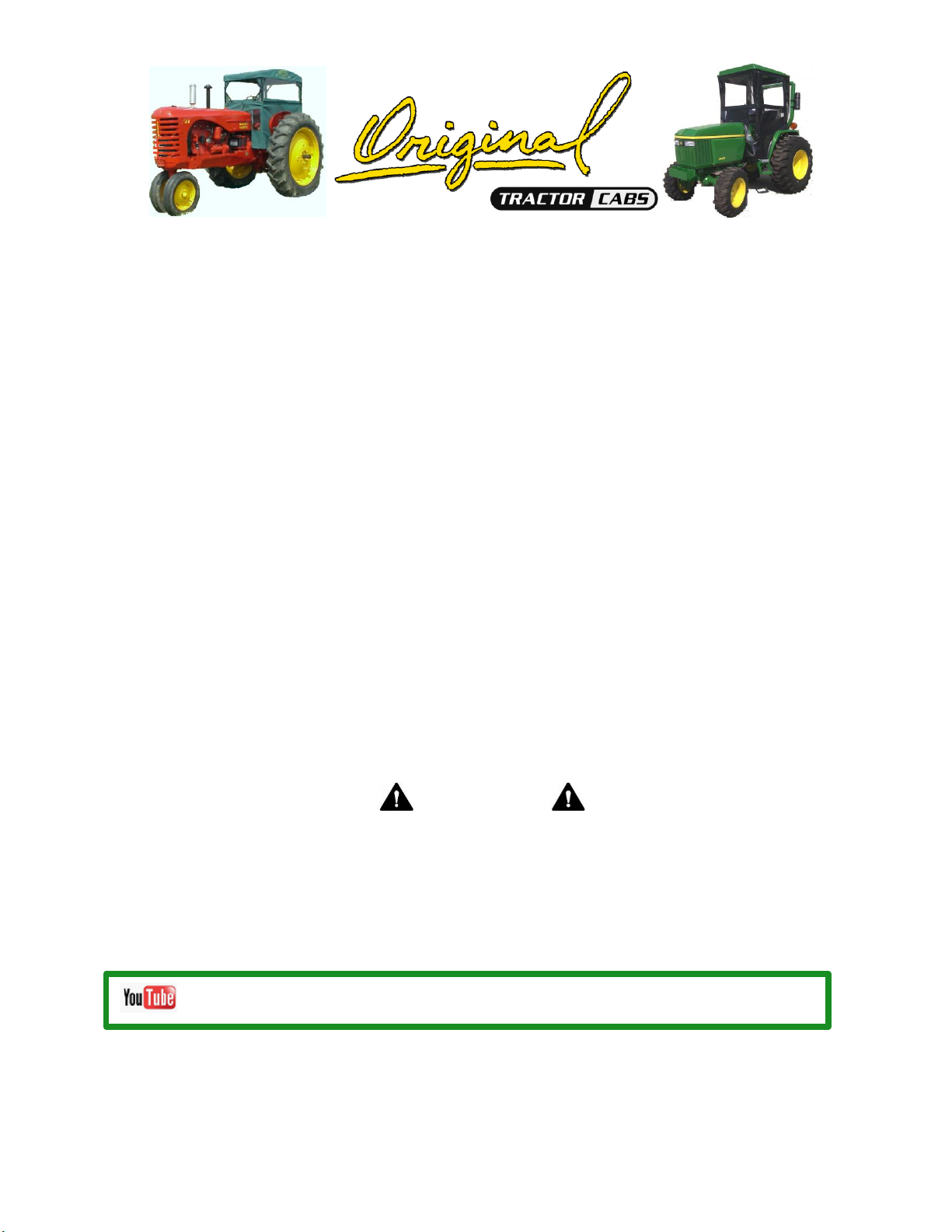
SNOW REMOVAL EQUIPMENT CABS
COVERED BY WARRANTY
ORIGINAL TRACTOR CAB CO., INC., (the "Company") warrants to the owner that each new product listed below is
merchantable and free of defects in workmanship and material.
During the warranty period, the dealer from whom the product was bought, or the Company, will provide, free of charge,
parts and the shipping costs of parts necessary to correct any defect in workmanship and material.
WARRANTY PERIOD
The company products listed below are warranted for the stated period from the date of the original purchase:
1. Cabs for tractors and snow removal equipment 1 Year
2. Company manufactured accessories for above cabs 1 Year
3. Sunshades for lawn and garden tractors 1 Year
4. Repair parts 1 Year
OWNER'S RESPONSIBILITIES
The owner of a new Company manufactured product must do the following to qualify for warranty service:
1. Retain the original invoice or other proof of purchase to avoid unnecessary difficulties in determining eligibility for warranty
work.
2. Notify the dealer from whom the product was bought, or the company, as soon as possible after discovery of a possible
defect, and provide proof of original purchase.
To notify the company write to: Original Tractor Cab Co., Inc., P.O. Box 97, Arlington, IN 46104.
3.The owner may, upon notification by the Company, be required to return the defective part, or parts, to the Company for
inspection and warranty service.
NOT COVERED BY WARRANTY
The following are not covered by this warranty:
1. Transportation charges to and from servicing dealer or the company.
2. New products which have been subject to misuse, negligence or accident, or have been altered or repaired in a manner
not authorized by the company.
3. Windshield wipers, lights, or accessories that are warranted separately by their respective manufacturers, except
company agrees to make available to the owner whatever warranty benefits may be made available to the Company by
the manufacturers.
All implied warranties, except to the extent prohibited by any applicable law, shall have no greater duration than
the warranty period for the applicable product, some states do not allow limitation on how long an implied
warranty lasts, so the above limitation may not apply to you.
The Company’s liability arising out of warranties representation, instructions, or defects from any abuse, shall
be limited exclusively to repair or replacing parts under the condition in the warranty, and in no event will
Company be liable for incidental or consequential damages. Some states do not allow the exclusion or limitation
of incidental or consequential damages, so the above limitation or exclusion may not apply to you.
This warranty gives you specific legal rights, and you may also have rights that vary from state to state.

3
WARNING
This cab is designed to provide foul weather protection only. It does not provide protection from
noise, exhaust fumes, chemicals or injury from roll-over, collision, or other accidents.
1. Do not operate machine in confined areas without proper ventilation.
2. Thoroughly check area of operation before using machine.
3. The cab adds height to the machine. Low tree limbs and other overhead structures that did
not interfere with the operation of the machine before, may now be obstacles.
MAINTENANCE INSTRUCTIONS
Periodically check all bolts to see that they are tight. If bolts become loose, failure of cab parts may
occur.
Door latches and hinges should be lubricated with light machine oil for proper operation.
DO NOT CLEAN THE CLEAR PLASTIC WINDOWS WHEN THE PLASTIC IS DRY.
THE CLEAR PLASTIC WILL SCRATCH.
Avoid contact with plastic windows. Keep plastic windows clean by washing them with clear running
water and rubbing with your bare hands, only. The use of a rag, sponge or brush will scratch the
plastic. Liquid soap may also be used for window cleaning. During freezing weather, an automotive
windshield washer solvent may be used.
Use liquid soap and water to clean colored vinyl portions. Scrubbing with a brush or rag is also
permitted on the colored vinyl portions.
STORAGE INSTRUCTIONS
Prior to storage clean the windows and colored vinyl parts with a mild automotive detergent, rinse
with clean water and allow it to thoroughly dry. Store cab in a clean dry place out of direct sunlight.
Avoid folding plastic windows.
INSTALLATION
READ THIS MANUAL COMPLETELY BEFORE BEGINNING INSTALLATION.
The right side of the machine is determined from the operators seated position.
The words "bolt" will refer to a 1/4”x5/8” bolt and "lock nut"’ will refer to a 1/4” lock nut unless
specified otherwise.
Do not tighten bolts during assembly unless instructed to do so.
Park vehicle on level ground and remove start key.

4
Carton Contents For Cab # 12278 Kioti CS2210, 2410, 2610
Key #
Part #
Qty.
Description
1
12279
1
Foot, RH
2
12280
1
Foot, LH
3
12281
1
Front Panel Frame
4
12282
1
Front Panel Frame Brace
5
12283
1
U Clamp
6
12287
1
Front Post, RH
7
10926
1
Front Post, LH
8
10002
1
Top Frame Brace, RH
9
10003
1
Top Frame Brace, LH
10
12232
2
Rear Bracket
11
12288
1
Rear Post, RH
12
40063
1
Rear Post, LH
13
12286
1
Rear Curtain Support
14
12289
1
Side Panel Support
15
12238
2
Vinyl Stay
16
12284
1
ROPS Bracket, RH
17
12285
1
ROPS Bracket, LH
18
12291-B
1
Rear Curtain
19
12292-B
1
Front Panel Vinyl
20
12293-B
1
Door
21
12294
1
Door Bottom
22
12295-B
1
Side Panel
23
10000
1
ABS Plastic Top
24
10001
1
Top Frame
25
10749
1
Windshield
9820-1
1
Door Hardware Package
12290
1
Hardware Package (Contents listed below)
786
18
1/4”-20 x 5/8” Bolt
788
3
1/4”-20 x 3/4” Bolt
0926
1
1/4”-20 x 1” Bolt
5144
2
1/4”-20 x 2 3/4” Bolt
0929
1
1/4”-20 x 3” Bolt
1514
4
1/4” Flat Washer
60217
25
1/4”-20 Nylock Nut
9448
4
M8-1.25 x 45mm Bolt
0784
2
5/16”-18 x 3/4”Bolt
9842
2
5/16”-18 Flange Lock Nut
60497
4
5/8” x 5/8” Heavy Wall Spacer
4902
2
Notched Vinyl Cap for Top of Rear Post

5
Step 1; See Figure 1:
Use the parts list and Figure 1 to identify the steel parts.
1
2
3
4
5
6
7
8
9
10
10
11
12
14
13
15
15
16
17
24

6
Tools Required:
7/16” Socket and Wrench
½” Socket and Wrench
17mm Wrench
19mm Wrench
¼” x 3”
¼” x 2-3/4”
M8 x 45mm
5/16” x ¾”
¼” Flat
Washer
¼” x 1”
¼” x ¾”
¼” x 5/8”
5/8” x 5/8”
Heavy
Wall
Spacer
5/16”
Flange
Locknut
¼” Nylock
Nut
Vinyl Cap

7
Step 2; See Figure 2, 2A and 2B:
Install Right Foot (1)
A. Remove the two bolts at Reference
A with a ½” socket.
B. Place two 5/8” x 5/8” spacers from
the hardware package over the bolt
holes as shown in Figure 2A.
C. Place the foot over the holes as
shown in 2B then insert two M8x45mm
bolts, do not fully tighten.
Figure 2
Figure 2A
Figure 2B
A
1

8
Step 3; See Figure 3, 3A and 3B:
Install Left Foot (2)
A. Remove the two bolts at Reference
A with a ½” socket.
B. Place two 5/8” x 5/8” spacers from
the hardware package over the bolt
holes as shown in Figure 3A.
C. Place the foot over the holes as
shown in 3B then insert two M8x45mm
bolts, do not fully tighten.
Figure 3
Figure 3A
Figure 3B
A
2

9
Step 4; See Figure 4, 4A, 4B, 4C and
4D:
Install Front Panel Frame (3)
A. Open the hood, place the feet of the
Front Panel Frame over the holes
shown in reference A and B.
B. Hold a 5/16” Flange lock nut under
the hole and insert a 5/16” x ¾” through
the Front Panel frame and the bolt hole
then repeat for the other side, do not
fully tighten.
Figure 4
Figure 4A
Figure 4B
Figure 4C
Figure 4D
A
B
3

10
Step 5; See Figure 5 and 5A:
Install Front Panel Frame Brace (4) and U Clamp (5)
A. Attach one end of the Front Panel Frame Brace to the tab on the left of the Frame
using a ¼” x 5/8” bolt and a nylock nut, do not fully tighten.
B. Put the U Clamp on the steering column using a ¼” x 3” bolt as shown in Figure 5,
attach the other end of the Front Panel Frame Brace to the outside of the U Clamp on
the bolt then add a nylock nut. Do not fully tighten.
Figure 5 Figure 5A
4
5

11
Step 6; See Figure 6, 6A and 6B:
Install Front Post (7) and Top Frame
Brace (9)
Note: Bent ends of Top Frame
Braces will point rearwards and lay
flat when properly installed.
Note: If you are installing the safety
glass windshield omit Top Frame
Braces.
A. Insert a ¼” x 5/8” bolt outward
through the hole in the Foot and the
lower hole in the Front Post. Add a
nylock nut, do not fully tighten.
B. Insert a ¼” x ¾” bolt forward through
the tab on the Front Post, the end of the
Front Panel Frame and then the lower
end of the Top Frame Brace. Add a
nylock nut, tighten just enough to
hold the brace up.
Figure 6
Figure 6A
Figure 6B
9
7

12
Step 7; See Figure 7, 7A and 7B:
Install Front Post (6) and Top Frame
Brace (8)
Note: Bent ends of Top Frame
Braces will point rearwards and lay
flat when properly installed.
Note: If you are installing the safety
glass windshield omit Top Frame
Braces.
A. Insert a ¼” x 5/8” bolt outward
through the top hole in the Foot and the
hole in the Front Post. Add a nylock nut,
do not fully tighten.
B. Insert a ¼” x ¾” bolt forward through
the tab on the Front Post, the end of the
Front Panel Frame and then the lower
end of the Top Frame Brace. Add a
nylock nut, tighten just enough to
hold the brace up.
Figure 7
Figure 7A
Figure 7B
8
6

13
Step 8; See Figure 8, 8A and 8B:
Install ROPS Bracket RH (16) and
ROPS Bracket LH (17)
A. Using a 17mm wrench, loosen the
nut holding the hazard light shown in
Figure 8.
B. Put the ROPS Bracket onto the bolt
behind the light as shown in Figure 8A
then tighten the nut.
C. Repeat on Right Side.
Figure 8
Figure 8A
Figure 8B
17

14
Step 9; See Figure 9 and 9A:
Install the Top Frame (24)
Note: The front of the Top Frame has
the “L” tabs located closest to the
corners.
A. Place The rear half of the Top Frame
onto the bent ends of the ROPS
Brackets.
B. Insert two ¼” x 5/8” bolts up through
the ROPS Brackets and add nuts, do
not fully tighten.
C. Attach the front half of the Top
Frame to the rear half and place it on
the bent ends of the Front Posts and
Top Frame Braces.
D. Insert four ¼” x 5/8” bolts up through
the Front Posts and the Top Frame
Braces. Add nuts, do not fully tighten.
Figure 9
Figure 9A
24

15
Step 10; See Figure 10, 10A and 10B:
Install Rear Post RH (11) and Rear Post
LH (12)
Note: Only the Rear Post LH (12) has a
door latch.
A. Insert a ¼” x 5/8” bolt up through the
Rear Post and the Top Frame. Add a
nut, do not fully tighten.
B. Repeat for left side.
Figure 10
Figure 10A
Figure 10B
11
12

16
Step 11; See Figure 11, 11A and 11B:
Install Rear Bracket (10) and Vinyl Stay
(15) on the Left Side
A. Slide the Rear Post Bracket onto the
ROPS and insert a ¼” x 2 ¾” bolt
outward through the Bracket and add a
nut, do not fully tighten.
B. Insert a ¼” x ¾” bolt through the front
hole of the Rear Bracket, the Rear Post
and the Vinyl Stay. Add a nut, do not
fully tighten.
C. Make sure the Rear Bracket is level
then tighten the bolt, tighten the bolt in
the vinyl stay so it remains straight up
and down.
Figure 11
Figure 11A
Figure 11B
10
15

17
Step 12; See Figure 12, 12A, 12B,
12C and 12D:
Install Rear Bracket (10), Vinyl Stay
(15) and Side Panel Support (14) on the
Right Side
Note: The bend in the Side Panel
Support (14) should go closer to the
back of the tractor as shown in Figure
12C.
A. Slide the Rear Post Bracket onto the
ROPS and insert a ¼” x 2 ¾” bolt
outward through the Bracket and add a
nut, do not fully tighten.
B. Insert a ¼” x 1” bolt through the front
hole of the Rear Bracket, the Rear Post,
the Side Panel Support and the Vinyl
Stay. Add a nut, do not fully tighten.
C. Attach the other end of the Side
Panel Support to the open hole in the
RH Foot using a ¼” x 5/8” bolt.
D. Make sure the Rear Bracket is level
then tighten the bolt, tighten the bolt in
the vinyl stay so it remains straight up
and down.
Figure 12
Figure 12A
Figure 12B
Figure 12C
14
10
15

18
Step 13; See Figure 13 and 13A
Adjusting the Loader Control Arm
A. Using a 19mm wrench, loosen the
nuts on the loader control arm.
B. Turn the arm in enough to where it
won’t contact the side panel support
then tighten the nuts.
Figure 13
Figure 13A
Step 14; See Figure 14:
Install Rear Curtain Support (13)
A. Place the Rear Curtain Support
between the Rear Brackets and insert
two ¼” x 5/8” bolts through the Support
then the Bracket. Add nuts, level the
support then tighten.
Figure 14
13

19
Step 15; See Figure 15:
Install the Door for Frame/Door
alignment.
A. Follow the instructions in the Door
Hardware Package to install the Door
Bottom and the Door Latch.
B. Install, close and latch the Door.
C. Tighten all bolts from previous
steps at this time.
D. Remove the door by lifting the door
up and out of the bottom hinge then
lowering out of the top hinge.
E. Place a plastic protector over the
bent ends at the top of each rear post.
Figure 15

20
Step 16; See Figure 16, 16A, 16B and
16C:
Install Rear Curtain (18)
A. Press the Velcro together around the
top frame at the back and corners.
B. Press the Velcro together over the
Rear Posts and Vinyl Stays.
Note: The bottom of the Rear Curtain
tucks in front of the toolbox.
Figure 16
Figure 16A
Figure 16B
Figure 16C
18
Table of contents
Other Original Tractor Cabs Tractor Accessories manuals

Original Tractor Cabs
Original Tractor Cabs 10121 User manual

Original Tractor Cabs
Original Tractor Cabs 30520 User manual

Original Tractor Cabs
Original Tractor Cabs 12297 User manual

Original Tractor Cabs
Original Tractor Cabs 11876 Datasheet

Original Tractor Cabs
Original Tractor Cabs CAB 12152 User manual

Original Tractor Cabs
Original Tractor Cabs 12022 Datasheet

Original Tractor Cabs
Original Tractor Cabs 4421381 Datasheet

Original Tractor Cabs
Original Tractor Cabs 12317 Datasheet

Original Tractor Cabs
Original Tractor Cabs 12244 User manual

Original Tractor Cabs
Original Tractor Cabs 9551 User manual