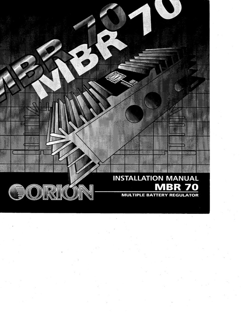
Orion MBR 70 User manual

INSTALLATION
MANUAL
_
MBR
70
MULTIPLE
BATTERY
REGULATOR


INTRODUCTION
You
have
purchased
the
finest
voltage
protection/charging
system
available
on
the
market
today.
The
Wired
MBR
70
incorporates
the
latest
technological
advancements
to
exceed
cur¬
rent
measurement
standards
of
performance,
craftsmanship
and
reliability.
Your
MBR
70
includes
these
built-in
features:
■
Isolates
batteries
when
ignition
is
off.
■
Mounts
in
front
or
rear
of
vehicle.
«
Senses
charge
voltage
of
auxiliary
batteries.
«
Brings
charge
voltage
up
on
the
vehicle's
battery,
then
begins
charging
the
auxiliary
batteries.
■
Enables
the
stereo
system
to
draw
off
all
the
batteries
when
engine
is
running.
*
Can
be
installed
without
cutting
into
factory
harnesses.
*
Has
LED's
to
inform
of,
POWER
and
CHARGE
status.
Wired's
MBR
70
takes
a
totally
new
approach
to
ensure
proper
voltage
levels
in
multiple
battery
systems.
The
MBR
70
is
a
"smart"
regulator/
isolator
that
senses
the
needs
of
the
vehi¬
cle's
battery
and
any
additional
batteries.
Unlike
conventional
battery
isolators,
the
MBR
70
requires
no
cutting
into
the
factory
electrical
system.
It
allows
all
the
batteries
in
your
vehicle
to
become
a
collective
voltage
source.
The
MBR
70
ensures
the
proper
voltage
level
in
the
vehicle's
battery
by
concentrating
solely
on
that
battery
until
it
sees
a
charge
voltage
above
12.5
volts.
Once
this
voltage
level
has
been
established,
the
MBR
70
couples
all
the
batteries
so
they
can
all
be
charged.
When
your
engine
is
running,
the
MBR
70
allows
the
alternator
to
feed
the
auxiliary
batter¬
ies
a
regulated
charge
up
to
70
amps.
When
the
ignition
is
turned
off,
the
MBR
70
becomes
a
"one-way
gate",
isolating
the
cur¬
rent
in
the
vehicle's
battery
from
passing
through
to
the
auxiliary
batteries.
This
"one-way
gate"
ensures
that
the
vehicle's
battery
will
always
have
enough
charge
to
start
the
car,
regardless
of
the
charge
level
in
the
auxiliary
batteries.

Wiring
diagram
Vehicle's
Battery
Fuse
holder

INSTALLATION
:
Tools
Required
,
«
Electric
drill
/drill
bits
■
*
*
Phillips
and
flathead
screwdrivers
■
l
■
Wire
cutters
/
strippers
•
•
■
Wire
brush
and
emery
sand
paper
■
»
Soldering
iron
and
solder
■
*
Felt
tip
pen
or
center
punch
■
■
Volt
/
ohm
meter
■
Requited
Parts
(not
included
in
this
package)
■
4
gauge
Wired
Power
Cable
(length
varies
depending
on
installation)
■
Two
Wired
battery
terminals
per
battery,
one
positive
and
one
negative.
■
Four
wired
ring
terminals
per
battery,
two
positive
and
two
negative.
■
Two
Wired
100
Amp
circuit
breakers
and
four
positive
ring
terminals.
■
Number
10
self
tapping
metal
screw
(to
attach
MBR
70's
ground
wire
to
chassis)
■
3/8"
lug
connector,
nut,
bolt
and
two
flat
washers
(one
set
per
battery)
■
One
Wired
Distribution
Block.
Utility
knife
Pliers
(standard
and
needle
nose)
Wire
crimping
tool
Rubber
grommets
Nylon
tie
wraps
Heat
shrink
tubing
Electrical
tape
General
Precautions
Before
installation,
make
sure
you
select
a
dry
location
that
will
provide
adequate
ventilation
around
the
MBR
70.
The
heatsink
has
fins
to
couple
generated
heat
to
the
surrounding
air
space
via
thermal
conduction.
We
recommend
that
you
mount
the
MBR
70
flat
on
the
floor
of
the
trunk
or
under
the
hood,
in
a
location
that
will
protect
it
from
water
damage.
Remember,
heat
travels
up
away
from
the
heatsink
fins.
improper
wiring
connections
can
seriously
damage
the
MBR
70
and
your
vehicle.
Be
sure
to
care¬
fully
follow
the
connection
instructions
in
this
manual.
NOTE:
If
you
are
not
sure
of
the
connections,
contact
your
dealer.
When
making
power
connections,
make
sure
that
each
connection
is
clean
and
properly
secured.
Failure
to
do
so
may
result
in
damage
to
the
MBR
70
and
your
vehicle.
In
addition,
please
observe
these
precautions.
■
Mount
the
MBR
70
in
a
dry
location,
■
Do
not
mount
the
MBR
70
on
a
plastic
surface
or
other
low
combustion
point
material,
»
Do
not
place
a
glass
or
metal
cover
over
the
MBR
70
unless
you
have
a
cooling
fan
at
one
end.
Direct
cool
air
along
the
length
of
the
fins,
rather
than
across
them.
»
Do
not
use
more
than
2
auxiliary
batteries
per
MBR
70.

WIRING
8k
MOUNTING
t.
Select
mounting
location
of
the
auxiliary
batteries
and
the
MBR
70.
Make
sure
you
observe
the
General
Precautions
listed
on
the
previous
page.
2.
Use
a
multi-meter
or
test
light
to
locate
the
ignition
wire
at
the
fuse
box.
Be
sure
that
it
reads
12
volts
positive
<+)
when
the
engine
is
running
and
0
volts
when
the
ignition
switch
is
off
(not
on
accessory).
Mark
this
wire
with
a
piece
of
electrical
tape.
3.
With
the
ignition
off,
disconnect
the
negative
{-)
lead
and
positive
(+)
lead
from
die
vehicle's
battery.
4.
Install
auxiliary
batteryfs)
with
manufacturer's
approved
hardware.
5.
Mount
a
100
amp
circuit
breaker
within
18
inches
of
the
vehicle's
battery.
WARNING:
Failure
to
install
a
circuit
breaker
at
this
location
could
result
in
severe
damage
to
the
MBR
70
and
your
vehicle.
6.
Route
a
4
gauge
power
wire
from
the
fuse
holder
to
the
proposed
location
of
the
MBR
70.
At
convenient
points,
fasten
the
power
wire
to
the
vehicle's
body
with
tie
wraps.
Use
this
technique
to
keep
the
wire
from
dangling
across
engine
compo¬
nents.
Use
rubber
grommets
where
power
wire
penetrates
sheet
metal.
CAUTION:
Do
not
connect
the
power
wire
to
the
battery
terminal
at
this
time.
7.
Position
the
MBR
70
and
use
either
a
felt-tip
pen
or
center
punch
to
mark
locations
for
the
mounting
holes.
Drill
a
small
pilot
hole
at
each
marked
location.
CAUTION:
Do
not
drill
into
the
fuel
tank,
fuel
lines,
brake
lines
(under
chassis),
or
through
any
electrical
wiring.
8.
Mount
a
100
amp
circuit
breaker
within
18
inches
of
the
auxiliary
battery(s).
WARNING:
Failure
to
install
a
circuit
breaker
at
this
location
could
result
in
severe
damage
to
the
MBR
70
and
your
vehicle.
9.
Remove
the
plastic
plug
on
bottom
of
the
MBR
70,
insert
the
4
gauge
power
wire
coming
from
the
circuit
breaker
mounted
in
step
5,
into
the
lug
marked
IN,
then
insert
a
4
gauge
power
wire
coming
from
the
circuit
breaker
mounted
in
step
8,
into
the
lug
marked
OUT.
10.
Be
sure
to
check
both
lugs
to
make
sure
you
have
made
a
solid
and
tight
connection
with
the
set
screws.
Snap
plastic
plug
back
into
the
access
hole,
then
mount
the
MBR
70
securely
in
the
desired
location
with
four
self-tapping
screws.
CAUTION:
Do
not
drill
into
the
fuel
tank,
fuel
lines,
brake
lines,
(under
chas¬
sis)
or
through
any
electrical
wiring.
11.
L
ocate
a
metal
chassis
component
that
is
within
the
reach
of
the
MBR
7Q's
attached
ground
(black)
wire.
Cut
away
any
carpet
and
scrape
off
the
body
paint
to
expose
bare
metal.
Be
sure
to
clean
the
area
with
sandpaper
until
you
see
a
bright,
shiny
finish.

12.
Drill
a
small
pilot
hole
{'/«“
diam.)
in
the
selected
area
and
use
a
No.
10
self-tapping
screw
to
securely
attach
the
crimped
lug
{on
the
end
of
the
ground
wire)
to
the
metal
chassis.
CAUTION:
Do
not
drill
into
the
fuel
tank,
fuel
lines,
brake
lines,
(under
chassis)
or
through
any
electrical
wiring.
13.
After
the
ground
has
been
properly
attached,
cover
the
exposed
bare
metal
with
paint
or
grease
to
prevent
rust.
14.
Route
the
red
wire
from
the
MBR
70
along
the
vehicle's
interior
wiring
channels
until
it
reaches
the
ignition
wire
you
previously
marked
with
tape
in
step
2.
Make
the
appro¬
priate
connections
and
watch
for
any
sharp
edges
on
passage
holes.
Use
rubber
grom¬
mets
where
ignition
wire
penetrates
sheet
metal.
15.
Locate
a
metal
chassis
component
that
is
within
18
inches
of
the
auxiliary
battery(s).
Be
sure
to
dean
the
area
with
sandpaper
to
expose
bare
metal.
Drill
a
Vs*
hole
in
the
selected
area.
CAUTION:
Do
not
drill
into
the
fuel
tank,
fuel
lines,
brake
lines,
(under
chassis)
or
through
any
electrical
wiring.
16.
Use
a
battery
terminal
and
ring
terminals
to
add
a
4
gauge
ground
wire
from
the
auxiliary
battery's
negative
{-)
post
to
the
chassis.
Securely
attach
the
wire
using
a
Vs"
lug
connector,
bolt,
nut
and
flat
washers.
17.
Connect
the
4
gauge
power
wire
coming
from
the
OUT
lug
on
the
MBR
70
.
to
the
100
amp
circuit
breaker
mounted
in
stepS.
18.
Connect
the
100
amp
circuit
breaker
to
the
auxiliary
battery(s)
positive
(+}
terminal
with
a
4
gauge
power
wire.
VI
19.
Use
a
battery
terminal
and
ring
terminals
to
add
an
additional
4
gauge
ground
^
wire
from
the
vehicle's
negative
(-)
battery
post
to
the
chassis.
Securely
attach
the
wire
using
a
Vs"
lug
connector,
bolt,
nut
and
flat
washers.
20.
Check
all
wiring
and
mounting
to
verify
proper
installation,
and
make
sure
the
vehicle's
ignition
switch
is
OFF.
21.
Use
a
battery
terminal
and
ring
terminals
to
connect
the
vehicle's
positive
{+)
battery
lead
to
the
circuit
breaker
mounted
in
step
5.
22.
Start
engine,
and
check
the
status
LED's
on
MBR
70.
The
MBR
70
should
be
on
and
should
show
charging
status
within
a
couple
of
minutes.
Note:
If
the
vehicle's
battery
is
low,
auxiliary
battery
charging
will
not
start
until
vehicle's
battery
has
a
charge
voltage
of
12.
S
volts.
BATTERY
TERMINAL

WARRANTY
&
SERVICE
ORION
warrants
this
product
to
be
free
from
defects
in
material
and
workmanship
under
the
following
terms:
PARTS
and
LABOR
are
warrantied
for
a
period
of
1
year
from
the
date
of
the
first
consumer
purchase
from
an
Authorized
ORION
Dealer.
Except
as
specified
below,
this
warranty
covers
ALL
defects
in
material
and
work¬
manship
in
this
product.
The
following
are
not
covered
by
this
warranty:
1.
Any
product
which
is
NOT
purchased
from
an
Authorized
ORION
Dealer.
If
you
are
uncertain
as
to
whether
your
dealer
is
authorized,
please
contact
ORION
(480)
705
5600.
In
countries
other
than
the
USA,
each
distributor
warranties
the
ORION
products
which
it
sells.
2.
Any
product
which
the
serial
number
has
been
defaced,
modified
or
removed.
3.
Damage
of
malfunction
resulting
from;
a.
accident,
misuse,
abuse,
unauthorized
modification
or
failure
to
follow
the
instructions
provided
with
the
product
b.
repair
by
anyone
NOT
authorized
by
ORION
c.
damage
due
to
shipping
(these
claims
must
be
presented
to
the
freight
carrier)
d.
removal
or
installation
of
the
product
e.
any
failure
that
has
NOT
been
caused
by
a
defect
in
material
or
workmanship
This
warranty
is
in
effect
for
the
original
purchaser
only.
ORION
will
pay
for
labor
and
material
expense
for
covered
items.
ORION
does
not
cover
removal
or
installation
charges,payment
of
shipping
charges
to
ORION,
payment
of
OUT-OF-WARRANTY
shipping
charges,
or
damage
to
other
property
caused
by
any
defects
in
this
product.
To
obtain
service,
take
or
ship
the
product
(pre-paid)
in
its
original
packaging,
if
you
do
not
have
the
origi¬
nal
packaging
the
product
must
be
packed
so
no
damage
will
incur
to
the
product
during
shipment
to:
ORION
Attn:
Repair
Department
9235
S.
McKemy
Street
Tempe,
AZ
85284
For
IN-WARRANTY
service
you
must
include
a
copy
of
the
original,
dated
sales
receipt,
including
serial
number,
from
Authorized
ORION
Dealer.
Please
also
enclose
your
name,
return
address
(No
P.O.
Boxes)
and
a
detailed
description
of
the
problem.
This
Warranty
gives
you
specific
legal
rights
and
you
may
also
have
other
rights
which
vary
from
state
to
state.
#ORION
HIGH
PERFORMANCE
CAR
AUDIO
9235
South
McKemy
Street
Tempe,
Arizona
85284
480.705.5600
9000-0094
REVB
Table of contents
Other Orion Controllers manuals

Orion
Orion VCB-X Quick start guide

Orion
Orion 41710 HP-RB1 User manual

Orion
Orion GPC Plus Controller Configuration guide

Orion
Orion vortex R10 User manual

Orion
Orion Multiple Battery Regulator MBR70 User manual

Orion
Orion OriLink 23408 User manual

Orion
Orion VCB-X Quick start guide
Orion
Orion SynScan GoTo User manual

Orion
Orion OPM-4260 User manual
Popular Controllers manuals by other brands

SKYDANCE
SKYDANCE V4-U manual

Banner
Banner DXM100 instruction manual

Baader Planetarium
Baader Planetarium Steeldrive II manual

SEW-Eurodrive
SEW-Eurodrive MOVI-C UHX45A Series manual

Siemens
Siemens 3TW7291-1A Installation, operation & maintenance instructions

Eliwell
Eliwell FREE Panel EVP 3300/C installation manual