ORKEL HiQ smartbaler User manual
Serial number:
Manufacturer:
Orkel AS Johan Gjønnes veg 25
N-7320 Fannrem Norway
Operator’s manual
Orkel HiQ smartbaler
Original operator’s manual. Published 2013
From serial number: 20319001

2
Congratulations on the purchase of your new Orkel HiQ Smartbaler
Orkel machines are well-known for their quality and strength. They are designed for use in
tough environments and high efficiency. This is the result of continuous product develop-
ment and thorough quality control prior to shipping. We have conducted an assessment pro-
cedure in accordance with the EC -machinery directive and the machine is CE-marked.
1.Introduction
1.1 Identification:
A plate, stating the round bailer serial number is located at the drag bars right side.
An additional serial number (wrapper) is stamped on the top of the left rear main frame.
Serial numbers must always be at hand when contacting your supplier to order spare parts or
any other technical support.
Before any operational use or maintenance of this machine, you must read the safe-
ty instructions in this manual. Read them carefully to ensure that you are familiar
with all the safety issues.
This Operator’s manual is standard for:
Orkel HiQ smartbaler, New Holland Rollbaler 135 Ultra, Case IH RB 544 Silage pack HD
Check that this Operator’s Manual matches your baler. We require that the instructions in
this manual are followed in order to maintain your personal safety and ensure the lifespan of
the machine. Remember – always state the serial number when ordering spare parts!
Information in the manual relating to personal safety is marked with
the above sign and with bold text. Please pay special attention to these sections.
Yours sincerely,
Orkel AS
Serial number (plate), round bailer Serial number, wrapper

3
INDEX:
1.Introduction
1.1 Identification
1.2 General
1.3 Dimensions and weight
1.4 Safety
1.5 Main sections
2. Safety instructions
2.1 Introduction
2.2 General safety instructions
2.3 Mechanical connection and disconnection
2.4 Adjustment
2.5 Maintenance and service
2.6 Lifting
2.7 Use
2.8 Transport
2.9 Parking
2.10 Dismantling
2.11 Warning signs/ labels
2.12 Warning signs, explanations
3. Connections
3.1 Electrical
3.2 Hydraulic
3.3 Mechanical
3.4 PTO axle
3.5 PTO speed
4 Settings
4.1 Height /tow bar adjustment
4.2 Settings in control box
4.3 Mechanical settings
4.4 Hydraulic settings
5 Preparations before driving
5.1 Installing the wide film or net roller to the HiT system
5.2 Installing wrapping film
5.3 Lubrication system. Refill
5.4 Ensiling fluid.

4
6. Start-up
6.1 Control before starting up
6.2 Control box, introduction
6.2.1 Control box unit, general function
6.2.2 Control box, menus
6.3 Driving technique
6.3.1 Driving technique, hillsides /slopes
6.4 Obstruction in pick-up or feeder unit
7 Technical information
7.1 Electric system
7.2 Hydraulic system
7.3 HiT system overview
7.3.1 HiT system, hydraulic valves
7.3.2 HiT valves, adjustment
7.4 Lubrication system
7.4.1 Lubrication system, troubleshooting
7.5 Drive chains
7.5.1 Sprockets
7.6 Sensor overview and location
7.6.1 Sensor scheme
7.7 Program menus
7.7.1 Main programs
7.7.2 Ensiling fluid/Additives
7.7.3 Timers and speeds
7.8 Program menu, screen pictures in control box
7.8.1 Program menu, chamber calibration
7.8.2 Program menu, pick up settings
7.9 Hydraulic scheme
7.10 Wrapper, manual operation
7.11 Wrapper film, overlap adjustment

5
8 Maintenance
8.1 Daily maintenance.
8.2 Knives
8.2.1 Knives, disassembly/assembly
8.2.2 Knives, changing/sharpening
8.2.3 Knives, control
8.4 Release lever Hit system, adjustment
8.5 Lubrication, manual points
8.6 Service
8.7 Cleaning.
8.8 Long time storage, winter storage.
8.9 Wheels and tyres
8.10 Jacking points
8.11 Spare parts
9 Contact
9.1 Vital phone numbers.
9.2 e-mail and webpage.
10 Technical data
10.1 Specifications
10.2 Options
11 Transport
11.1 Tying down / strap
11.2 Lift/Hoist
11.3 Parking
12 Declaration of conformity
13 Warranty
13.1 Terms and conditions
13.2 Warranty and warranty claims
14 Notes:

6
1.2 General
The Orkel HiQ Smartbaler is meant for baling grass, straw and hay, and for these
purposes only. The HiQ is a high effective baler, designed for farmers and
entrepreneurs acting on a larger scale.
The bales will have a diameter up to 1300 mm, and a width of 1220 mm.
The bales might weigh 1000 kg or more.
The HiQ Smartbaler has to be used accordingly to the instructions given in this
manual.
If you are in doubt regarding the range of use of the machine, contact Orkel AS, or
your local Orkel representative.
1.3 Dimensions and weight:
HiQ smartbaler (Rollbaler 135 Ultra / RB 544 Silage pack HD)
Weight: 5200Kg
Height: 280cm
Width: 275/292cm
Length: 620cm
1.4 Safety
Before any use, or doing any kind of work on the machine, the
“safety instructions” in chapter 2 has to be read carefully and understood.
7
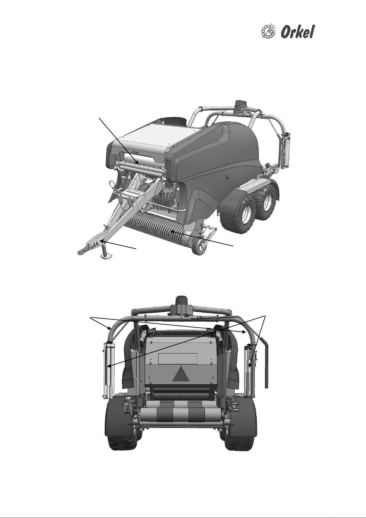
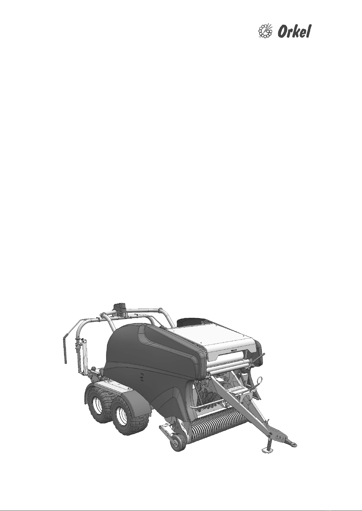
1.5 Main sections
Drag bar
Net/film holder
Pick up
Wrapper
Wrapper table
Wrapper arms Film holders
Chamber
8
2. SAFETY INSTRUCTIONS, INDEX
2.1 Introduction
2.2 General safety instructions
2.3 Mechanical Connection/disconnection
2.4 Adjustments
2.5 Maintenance
2.6 Lifting
2.7 Use
2.8 Transport
2.9 Parking
2.10 Dismantling
2.11 Label warnings
2.12 Label warnings, explanation

9
2.1 Safety introduction
Danger of severe injury is present if the machine is not being handled pursuant to
descriptions made in this Operator`s manual /safety instructions.
All care and attention has been taken in design and production of this Orkel machine, to min-
imize the danger in operating the baler. However, there is a certain amount of risk to person-
nel operating the baler. It is strongly recommended that the operators, take all possible pre-
cautions to ensure both their own safety, and others who may be in the area.
NOTE: Orkel HiQ smartbaler can only be used for baling grass, hay and straw!
Before operating, adjusting or servicing the machine, it is important that operators manual
and safety instructions are carefully read and understood by the operator.
Operator’s manual should be regarded as a part of the machine. Make sure this guide is fol-
lowing the baler if “resale”
By reading this operator’s manual you will be able to understand:
1 How the machine operates.
2 How to operate it safely without hazard to either the operator or persons in the area
3 How to successfully use the machine to its fully potential.
WARNING: Ignoring the safety instructions can result in death or serious injury!

10
2.2 General safety instructions
Before any maintenance, cleaning, disassembly of parts and adjustment is made on the ma-
chine. Always: Disengage the PTO drive clutch. Stop the tractor engine, activate the hand
brake and remove the key to prevent the tractor from being started accidentally.
Before operation:
Thoroughly read and understand the relevant chapter in the operators manual. Do not start
the tractor before all persons are in safe distance to the machine. Keep children and specta-
tors off and away from machine when operating. The area around the machine should be
kept clear at all times. Keep area between tractor and baler clear of people under coupling
and uncoupling.
Operation:
Do not wear loose or baggy clothing, when working on the machine and keep hands, feet
and clothing away from moving parts. Stop tractor engine before removing guards and
shields. Keep all guards and shields in place and in correct order. Use ear protection if the
noise of the machine and tractor is too loud. (without cabin)
It is not allowed to stay on the machine when operating.
Never remove material from machine when operating, and never feed material (twine, net or
crop) manually into machine. Stop tractor engine and remove the key before unblocking pick
up.
When baling dry material like dry grass, hay or straw, extra care has to be taken.
Service/maintenance:
Before starting, make sure of the machine is clear of people, and that all tools and loose ob-
jects have been removed and correctly stowed. Do not do service or remove hydraulic hoses
when the hydraulic system is under pressure.
Owner:
The owner is responsible for making this information available to the operator. This to en-
sure safe use and proper maintenance of the baler.
WARNING: CHILDREN UNDER 16 YEARS OF AGE MUST NEVER OP-
ERATE THE MACHINE!
Table of contents
Other ORKEL Farm Equipment manuals


Popular Farm Equipment manuals by other brands

Schaffert
Schaffert Rebounder Mounting instructions

Stocks AG
Stocks AG Fan Jet Pro Plus 65 Original Operating Manual and parts list

Cumberland
Cumberland Integra Feed-Link Installation and operation manual

BROWN
BROWN BDHP-1250 Owner's/operator's manual

Molon
Molon BCS operating instructions

Vaderstad
Vaderstad Rapid Series instructions


