ORKEL hiQ Smartbaler User manual

User`s manual
Orkel hiQ Smartbaler
2012
Serial number, baler:
MANUFACTURER:
Orkel AS Serial number; wrapper:
7320 Fannrem

2
Congratulations on the purchase of your new Orkel hiQ Smartbaler
Our machines are renowned for their quality and strength, and are designed for use in tough
environments. This is the result of continuous product development and thorough quality
control prior to shipping the machinery. We have conducted an assessment procedure in
accordance with the Norwegian machinery directive (DECLARATION OF
CONFORMITY) and the machine is CE-labeled accordingly.
Plates stating the serial numbers are located at the front (baler) and on the left main
frame (wrapper). Serial numbers must always be at hand when contacting the sup-
plier to order spare parts or for other technical support.
Plates stating the serial numbers are located at the front (baler) and on the left main
frame (wrapper). Serial numbers must always be at hand when contacting the sup-
plier to order spare parts or for other technical support.
Being the owner of the machine, you must read this USER`s MANUAL, including
the SAFETY INSTRUCTIONS before starting to use the equipment, or before ser-
vicing the baler. Read the User Guide carefully and get familiar with the require-
ments for machine safety, use and maintenance, and make daily service a part of
your routine.
Check that this User`s Manual matches your baler. We require that the instructions
in this User Guide are followed in order to maintain your personal safety and ensure
the lifespan of the machine.
Remember – always state the serial number when ordering spare parts!
(This User Manual refers to combined balers with serial numbers from 20319001…
Certain information in this User Guide is labeled with this sign
and/or by bold text. Please pay special attention to this information!
Orkel AS

3
Table of contents:
Part 1 Introduction
1.1General 5
1.2Safety 5
Part 2 Warranty. Declaration of conformity
2.1 Warranty. 6
2.2 Declaration of conformity 8
Part 3 Connections
3.1Electric 9
3.2 Hydraulic 9
3.3Mechanic 10
Part 4 Settings
4.1 Height adjustment 11
4.2 Program settings 12
4.3 Mechanical settings 12
4.4 Hydraulic settings 12
Part 5 Preparations for driving
5.1 Installing the wide film or net roller. 13
5.2 Installing the wrapper film roller.. 14
5.3 Adding grease to the lubrication system 15
5.4 Adding oil to the chain lubrication system 15
5.5 Ensiling fluid. 15
Part 6 Start-up.
6.1 Explanations to the control unit. 16
6.2 Control routines. 17
6.3 Driving 18
6.4 Blocking in pick-up/ feeder unit 20
Part 7 Technical information and descriptions
7.1 Cutting device 21
7.2 Hit system, overview 22
7.3 HiT system , hydraulic adjustments 23
7.4 Lubrication system 24
7.5 Drive chains 25
7.6 Sensor scheme 26
7.7 sensor scheme, wrapper 27
7.8 Program menus 28
7.9 Baling programs, explanations 35
7.10 Program menus continues 37
7.11Bale chamber calibration 40
7.12Wrapper film overlap, how to adjust 43
7.13Pickup. Settings in program 44

4
Part 8 Maintenance
8.1 Daily maintenance. 45
8.2 Manual lubrication. 46
8.3 Service. 48
8.4 Cleaning. 48
8.5 Long time storage. 48
Part 9 Contact
9.1 Vital phone numbers. 49
9.2 e-mail and webpage. 49
Part 10 Technical data
10.1 Technical data 50
Recommended settings:
10.2 “Baling programs” 51
10.3 “Additive” 52
10.4 “Timers and speeds” 53
Part 11 Important safety instructions
Index 56
10.1 Introduction. 57
10.2 General safety instructions. 58
10.3 Connecting and disconnecting. 59
10.4 Adjustments 60
10.5 Maintenance and service 60
10.6 Lifting 61
10.7 Use 61
10.8 Transport 61
10.9 Parking 61
10.10 Dismantling 61
10.11 Warning signs/ labels. 62
10.12 Warning signs. Explanations. 64

5
Part 1. Introduction
1.1. General
This Orkel hiQ Smartbaler is meant for baling grass, straw and hay, and for these
purposes only.
The bales will have a diameter of 1220 mm or more, and a width of 1220 mm.
The bales might weigh 1000 kg or more.
The hiQ Smartbaler has to be used accordingly to the instructions given in this
manual.
If you are in doubt regarding the range of use of the machine, contact Orkel, or
your local Orkel representative.
1.2. Safety
Before using the machine, or doing any kind of work on the machine, the
“important safety instructions” section, pages 58 - 66 has to be read and
understood.
Fire hazard! Especially when baling dry material like dry grass, hay or straw, ex-
tra care has to be taken. Under these conditions a fire extinguisher should always
be at hand. Even more hazardous is dry material mixed with oil.
Using the machine in a safe and correct way, will ensure an optimum utilization
from your Orkel hiQ Smartbaler, with regard to both stable working, fodder quality
and economy.

6
Part 2 Warranty. Declaration of conformity.
2.1 Warranty
Terms for end user:
Orkel AS warrants this machine against manufacturing defects for a period of 12 months from
the date of delivery to the end user.
The warranty is limited to:
1. The present value of the machine based on the maintenance performed, use and
condition.
2. The value of the damaged components.
3. Work hours calculated by Orkel AS.
4. Extent of repairs preapproved by Orkel AS.
Orkel AS is, under no circumstances, responsible for damage/circumstantial damage to third parties that may
be caused by the machine.
Important exceptions:
Ordinary wear and tear to rubber parts, tires, hydraulic hoses, blades, chains or bearings is not
covered by the warranty.
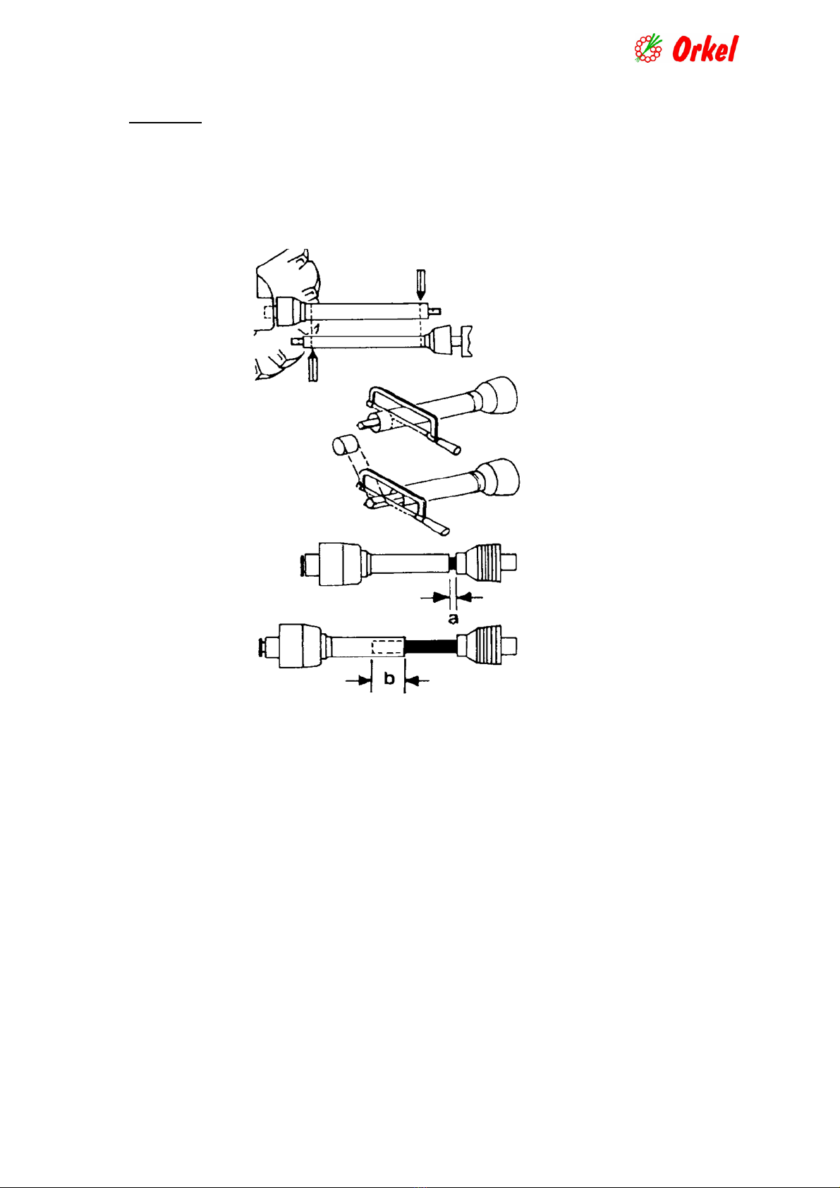
For the power transmission shaft, the supplier’s warranty regulations apply - see separate infor-
mation concerning the shaft.
The use of non-genuine parts, incorrect use and/or insufficient maintenance of the machine will lead to the can-
cellation or invalidation of the aforementioned warranty.
Extended warranty for slide bearings (bushings.
For machines with factory-mounted, fully automatic greased bearings, a 5-year warranty
(maximum of 50,000 bales) applies from the delivery date, for all slide bearings (bushing) for
rolls, based on the following:
Breakage to the slide bearing (bushing) is defined as material thickness of less than 0.2
mm.
Working hours for replacement are not included.
This warranty only applies if regular inspections and maintenance have been carried out
accordingly to the instructions outlined in this User Guide.
Extent and terms of the warranty:
The warranty covers the following situations:
Repair of faults caused by faults in the construction, materials, components, production,
mounting, alterations made by the factory or similar faults.
Faults and defects discovered before or after the product has been delivered to the cus-
tomer.
The product will be replaced or repaired as soon as possible, should a production or con-
struction fault occur, that potentially could represent a safety risk.
The terms of the warranty are not applicable if the defect/fault is caused by:
The product has not been handled according to the instructions provided by Orkel.
The product has not been serviced according to the instructions provided by Orkel..
The product has been modified,
The product has been installed or repaired, not corresponding to the instructions provided
by Orkel.
Non-genuine parts or standard components, not approved by Orkel, have been used.
Warranty work
Warranty work can only start after a specific agreement with the Orkel warranty representative.
Warranty work can be carried out either by the customer, an Orkel dealer or other workshop
preapproved by Orkel
To be continued next page.

7
Documentation
Orkel’s warranty claim form must be used when contacting Orkel for any type of warranty
repairs. This form is found at Orkel’s website www.orkel.no or can be sent by Orkel via email or
regular mail, on request.
The claim form must include information on:
Product type, serial number, purchase date, and the date when the problem occurred.
A description of the fault, and necessary actions to be taken.
Parts, including the number of parts used and their part numbers, if such parts are used.
Reference to an invoice or shipping note showing the spare parts used.
The report must be sent to Orkel no later than 1 month after the repair has been carried
out. Orkel must state any objections against the claim within 1 month after receiving the
claim.
Compensation
Payment deadline.
Orkel is committed to pay the approved compensation within 2 months after receiving the claim.
Compensation limits.
Orkel compensates the material costs of the replaced parts, products or components based on the
information provided by the owner, Orkel representative or Orkel’s internal documents.
If the received claim form lacks documentation, information or parts, we will send an inquiry
form. The missing information (or parts) must be received by Orkel no later than 1 month after
receiving the inquiry form.
All reports received by Orkel subsequent to the deadline will be rejected unless otherwise agreed.
Consequential damage
Consequential damage is not covered by this warranty, or any other Orkel warranty.
Transportation damage
Any complaints must always be directed to the transport company who caused the damage.
Returning damaged components
Components must be returned to Orkel upon request or should be kept stored for a minimum of 6
months.
Orkel might require photographs , instead of returning the faulty parts . A photo of the damaged
part should be included with the warranty claim form as required documentation.
Refund of shipping costs
Orkel will recommend a transport company and a return date. Any shipping costs not preap-
proved by Orkel AS, will not be refunded.
Orkel AS
Magne Sletvold
Warranty Manager

8
2.2 DECLARATION OF CONFORMITY
Orkel AS
N – 7320 Fannrem
Hereby declare that the following product:
Orkel hiQ Smartbaler, round baler
with baler, serial number: .............................................................
and wrapper, serial number: ……………………………..…………….
is covered by this declaration and in conformity with the following standards or other nor-
mative documents:
NS-EN 12100 (2003), NS-EN 292-1 (1991), NS-EN 292-2 (1991), NS-EN 704 (1999)
In accordance with the MACHINERY DIRECTIVE – 2006/42/EC (98/37 EU).
Fannrem, February 2012.
Leif Haugum
Project Engineer

9
Part 3. Connections
3.1 Electric connections.
The power supply cable, supplied by Orkel, has to be connected to the tractor`s
battery. This cable is then connected to the equivalent cable on the baler. This
is the only approved way for connecting electric supply to the baler.
The control cable has to be connected between the control unit and the equiva-
lent cable at the baler.
The lighting cable from the baler then has to be connected to the lighting output
at the tractor.
3.2 Hydraulic connection
Connect the brake hose of the baler to an approved brake outlet at the tractor.
Connect the pressure and return hoses to the tractor. Note that the return hose
has to be connected in a way that secures minimal back pressure (max 3 bar).
If the tractor is equipped with LS (Load Sensing) hydraulics, the signal hose
from the baler`s LS valve has to be connected to the LS distributor block of the
tractor. Additionally, to be able to take advantage of the LS, the function Load
Sense has to be turned on (1), in the program of the baler.
The pickup is normally operated from the control unit. However, a separate
hose could be connected to the tractor. The pickup will then be operated by the
tractor hydraulics.
3.3 Mechanical connections:
Connect the baler`s drawbar to the pulling device on the tractor.
For installation of the PTO axle, please see next page.

10
3.4 PTO axle.
Install the axle, and adapt to correct length (see figure )
Make sure that distance ais sufficient to handle necessary free motion when operating
the machine in hilly conditions, and that distance bis as long as possible. Lubricate the
axle in accordance with the manufacturer`s instructions. Please see separate manual for
PTO axle.
For instructions regarding height adjustments, please see next page.

11
4. Settings
4.1 Height / drawbar adjustment.
To obtain optimized utilization of the baler`s qualities, it is vital that this adjustment is
carried out in a correct way.
Preparations.
The baler has to be attached to the tractor.
Tractor and baler has to be placed on flat ground.
Air pressure in tires has to be set to 1 Bar.
Procedure.
1. Adjust Pick Up wheels until the pickup springs have a 5 cm distance to the ground.
2. Place a jack under the baler (see picture 1), and lift a little bit just to unload
weight
3. Loosen the fastening bolts for drawbar.
4. Loosen the locking nuts on adjustment bolts.
5. Lower the Pick Up until wheels are touching the ground.
6. Adjust with the jack until 2-3 cm remains before the cylinder reaches bottom. (See
picture 2).
7. Tighten the drawbar`s fastening bolts to a torque of 574 Nm.
8. Note! Retighten these bolts after a short time of driving!
Picture 1
Picture 2

12
4.2 Program settings
These settings are normally set correctly from the Orkel factory
If changes are necessary, this will be carried out by Orkel service personnel
during start up service, or contact your Orkel dealer.
If further adjustments are needed, please contact your dealer and/or see this
manual`s section “Recommended settings”, pages 51 - 53.
See also this manual`s section 6.1. ”explanations to the Control Box”, page.
4.3 Mechanical settings
These settings are normally set correctly from the Orkel factory.
If changes are necessary, this will be carried out by Orkel service
personnel during start up service, or contact your Orkel dealer
If further adjustments are needed, please contact your dealer or
Orkel Technical Dept., or find additional information in this manual
4.4 Hydraulic settings
These settings are normally set correctly from the Orkel factory.
If changes are necessary, this will be carried out by Orkel service personnel
during start up service, or contact your Orkel dealer
If further adjustments are needed, please contact your dealer or
Orkel Technical Dept., or find additional information in this manual.

13
5. Preparations for driving.
5.1 Installing wide film or net to the HiT system
Lift the front of the HiT unit by operating the lever on the front right hand side.
Film or net roller is easiest installed from the side of the baler. See to that the
roller is installed with the free end of net or film pointing upwards in front.
Lead the film or net as shown in sketch (as seen from the left hand side). This
sketch can also be found at a label on the left hand side of the machine.
Note! The blue line indicates treading of film,, and the red line indicates the
treading of net.
Lever
Orkel part # 16162
= Guide way net
= Guide way film - plastic

14
5.2. Installing wrapping film.
Unlock the upper film holder by lifting the locking handle. (see figure 1
Push the pre-stretch unit against centre of the wrapper, until it stays in
open position by itself.
Push the lead bracket upwards and lock it..Install the new roller, bottom
first. Keep the upper end of the roller centred.
Move the bracket downwards.
Fix the roller in correct position by pushing down the locking handle.
Lead the film correctly, in accordance with figure 2.
Tie the two film ends together in centre, and fasten the free ends down
to the wrapping table.
Set the number of film layers in the program.
Pre-stretch unit
Bracket
Locking handle
Figure2.
Figure1.

15
5.3. Filling the automatic lubrication systems.
Fill the reservoir for oil lubrication (chains) with engine oil 10W-40.
Fill the reservoir for grease lubrication (bearings) with grease type EP2. Al-
ways put the protection back to the nipple after use, to protect against dirt.
Both reservoirs have marks for minimum and maximum.
Always keep the level of filling between these marks.
Oil reservoir Grease reservoir Nipple for grease filling
5.4 Ensiling fluid.
There are several brands of acid pumps. We recommend reading each manufac-
turer`s manual, for the actual type. If the pump is supplied by Orkel, the manual
for the pump will be included in the documents following the machine
For pump type Prodevice PDH 10, there is a special program in the
Control Box for operating this particular pump.

16
6. Start-up
6.1 Explanations to the control unit, Type ACC, from program version 5.4PH
Structure:
In the information field, you can see information on the status of the baler, the
date, time, counter, knives up or down and additive on or off. The information
in this field of the display will be different in the different program menus.
In the menu/function field, you can activate the different functions of the
baler. The functions can be activated by pressing the adjacent select button at
the bottom or side of the display. These buttons are impulse contact type so
there is no need to press hard. A sound signal indicates that a command has
been accepted. The buttons operate different functions in the different program
menus.
When the Menu button is pressed you go to the next main menu.
The Cancel/Back button is used to exit a menu or to cancel an automatic func-
tion. By pressing this button, you return to the baler start screen.
Once electricity is connected to the control unit, you have the option to choose your
preferred language.
To reset the control box program, press menu button, cancel button and upper right
hand button simultaneously, and hold for 1-2 sec. This is an option, if the automatic
process has been interrupted in any way.
WARNING: This must only be carried out when the machine is not turning, and is
unloaded!
INFORMATION FIELD
MENU/FUNCTION FIELD
CANCEL/BACK BUTTON
SELECT BUTTONS
MENU BUTTON

17
6.2 Control routines.
These controls are normally carried out by your Orkel dealer.
Check that the rotational speed (RPM) is registered in the display of the Con-
trol Box.
Check that the pump for grease lubrication of bearings is rotating
and that the bearings are being lubricated.
Check that the oil lubrication for chains has normal function.
Check for unpleasant sounds or irregular functions.
Let the machine run without load for at least 20 minutes at first
start-up, before it is put to work.
Stop the machine and make sure there is no excessive heat
in any bearing.
If irregularities are discovered in any of these points, stop the machine im-
mediately and contact your local dealer or Orkel Technical Department!

18
6.3 Driving technique
Start the PTO while tractor engine is idling. Also engage the hydraulic system if Load Sense is not in use.
Gradually increase to 580-620 RPM (540 pto) or 820-850 RPM (1000 pto). When correct rotation speed is ob-
tained, a text “baling 1” and an arrow symbol will appear in display. This indicates that the machine is ready
for baling and that the propulsion can start.
The quality of the bale depends a lot on the driving technique, and the driving pattern.
The way to plan the driving pattern is dependent on the amount of grass, and weather the grass swath is wide or
narrow.
If there is not much grass present in the swath (1-2 bales per decare), and the width of the feeder cannot be
filled out, it is advised to move determined from side to side, in sections of 10 – 20m, but not in a “S-pattern”.
(See figure 1). This has to be done to obtain an even filling on the full width of the bale (see picture 5, 6 and 7)
and to ensure good cutting. Driving from side to side is less relevant when the amount of grass in the swath is
higher (3-4 bales per decare), and the feeder width is filled sufficiently.
Figure 1. driving pattern
Driving speed should be adapted to the amount of grass. At normal amounts of grass the speed could be up to 8
-10 km/h at start, to obtain a rapid start of filling the chamber with grass. At small amounts of grass, the driving
speed can be relatively high (10km/h or a little higher), as the cutting device achieves a better cutting with a
certain amount of grass in the feeder rotor. At large amounts of grass or when more swaths are collected to one,
the speed should not exceed 5-7 km/h at start. When column for chamber filling (see fig.2) is starting to get
filled, the speed should be lowered significantly, to obtain a good compression of the bale. The last few meters,
the speed should be as low as 3-4 km/h with normal grass amount and even slower when there is more grass.
This also protects the driving line from unnecessary and excessive loads during the baling process.
Figure 2. Column for chamber filling.

19
Driving technique continues
When stop signal, indicating full bale, is visible and audible, stop the propulsion and wait for some seconds
before starting the net/film tying. This gives some extra compression to the bale, before net or film is applied.
This also makes the applying of wide film work smoother. When net/film tying is in ”auto” mode, the tying
will start automatically.
Figure 3. Stop signal
Figure 4. Correctly shaped bale. The whole width Figure 5. Faulty shaped bale. Different diameter
Is evenly filled on the 2 sides.
Figure 6. Faulty shaped bale. Lack of grass in the middle section.

20
6.4 Blocking in pickup/feeder unit:
From time to time you can experience that excessive amounts of grass may lead to blocking
in the pickup and/or the feeder rotor. Follow this procedure to solve the problem:
1. Disengage the knives, lift and lower the pickup a couple of times to see if the
blocking loosens. This may solve the problems in some cases.
2. If possible, unload the bale from the chamber.
3. Stop PTO.
4. Push the button for reverse in the control unit.
5. Start the PTO carefully, and let it run for just a very short period of time.
6. Check that the blocking has loosened.
7. Push the button for reverse, to go back to normal rotational direction.
8. If this procedure is carried out while a bale is present in the chamber, this will give
some extra load to the driving line. Check components like PTO axle, safety
clutch, chains and chain tensioners for damage.
9. When the problem is solved, start PTO, engage the cutting knives and continue the
baling.
Other manuals for hiQ Smartbaler
1
Table of contents
Other ORKEL Farm Equipment manuals
Popular Farm Equipment manuals by other brands

MacDon
MacDon M2170 Operator's manual

Ferrari Costruzioni Meccaniche
Ferrari Costruzioni Meccaniche FX Use and maintenance

breviglieri
breviglieri MG-4 Operating and maintenance manual

Tufline
Tufline TW6 Series Operator's manual

Agria
Agria Taifun 5900 Series Translation of the original operating instructions

Anderson
Anderson A-INL-032 manual

Quick
Quick Unigrip 130 Operator's manual

Shelbourne Reynolds
Shelbourne Reynolds Powermix Pro Express Operator's manual

Woods
Woods BRUSHBULL BB48XE Operator's manual

Landoll
Landoll Brillion LSP5 Operator's manual

Spudnik
Spudnik 1860 Operator's & parts manual

Jay-Lor
Jay-Lor Because Nutrition Matters 4000 Series Operator's manual