1.3 Pegasus BT-POM 1212 - Rev 3
Important Information
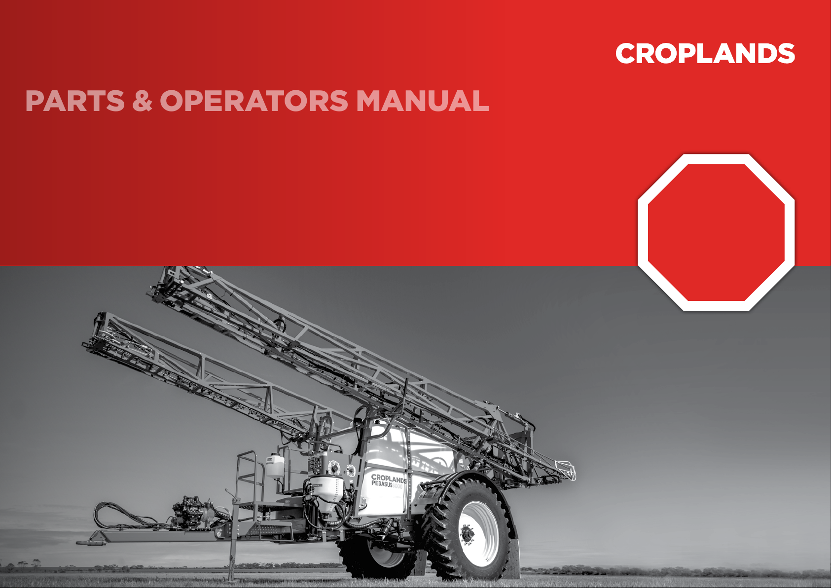
General Description &
Specications
Tank
4000, 5000 or 6000 litre polyethylene
tank with hinged lid, lling strainer, top/
bottom ll point, large sump with drain,
dual agitators, direct chemical induction
& tank rinsing jet. Calibrated sight gauge
tted. UV and chemical resistant nish.
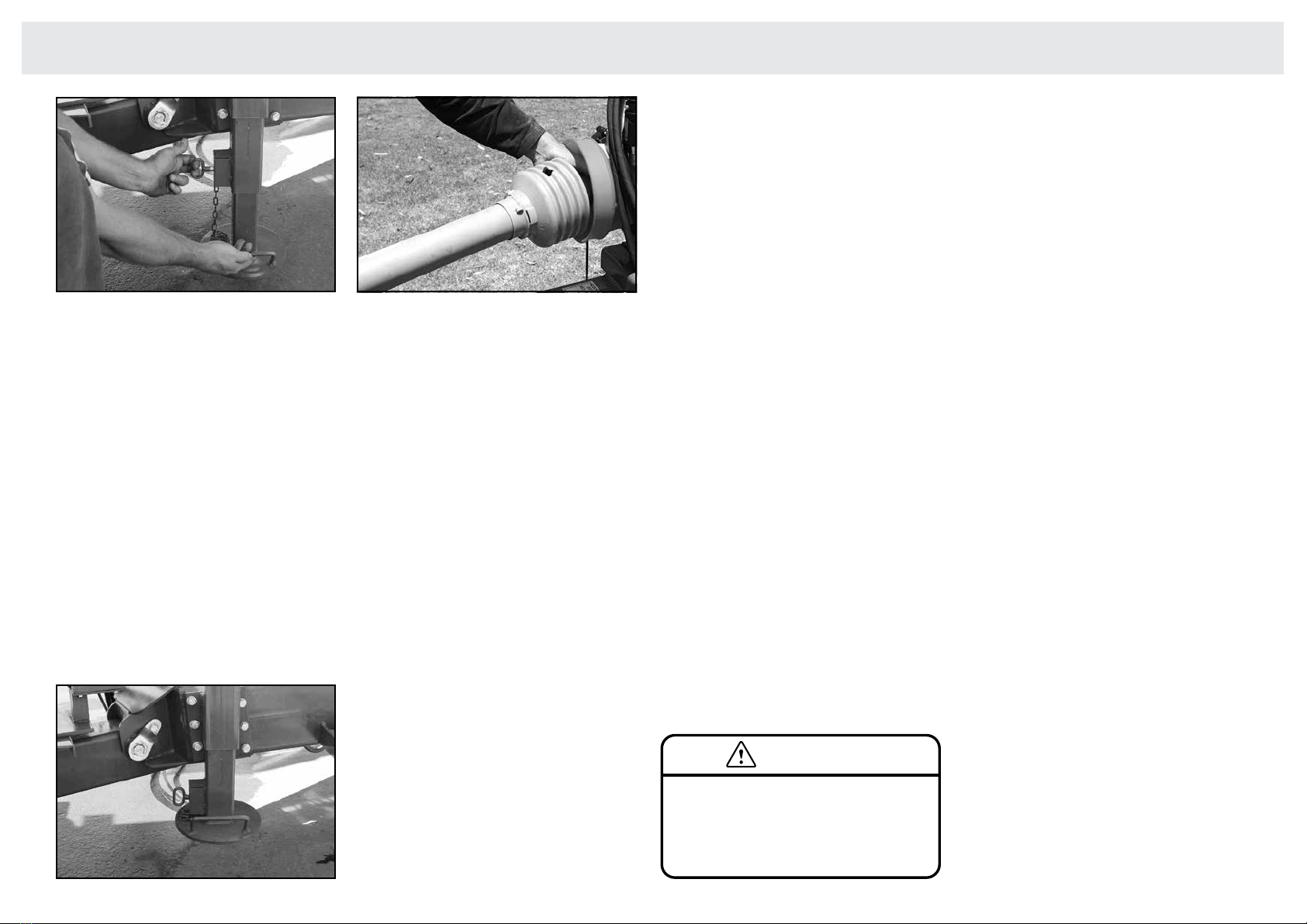
Chassis
Strong, fabricated wide-rail chassis, fully
welded for maximum strength. Standard
with solid xed-width axle. Adjustable-
height drawbar hitch with cast swivel eye
and heavy duty jack-stand. Optional air
suspension axle and/or adjustable track
axle, 2.1 – 3 metres.
Wheels & tyres
18.4 x 38” on 4000 & 5000 litre models;
20.8 x 42” on 6000 litre models;
Mudguards optional (all models).
Mudaps optional (all models).
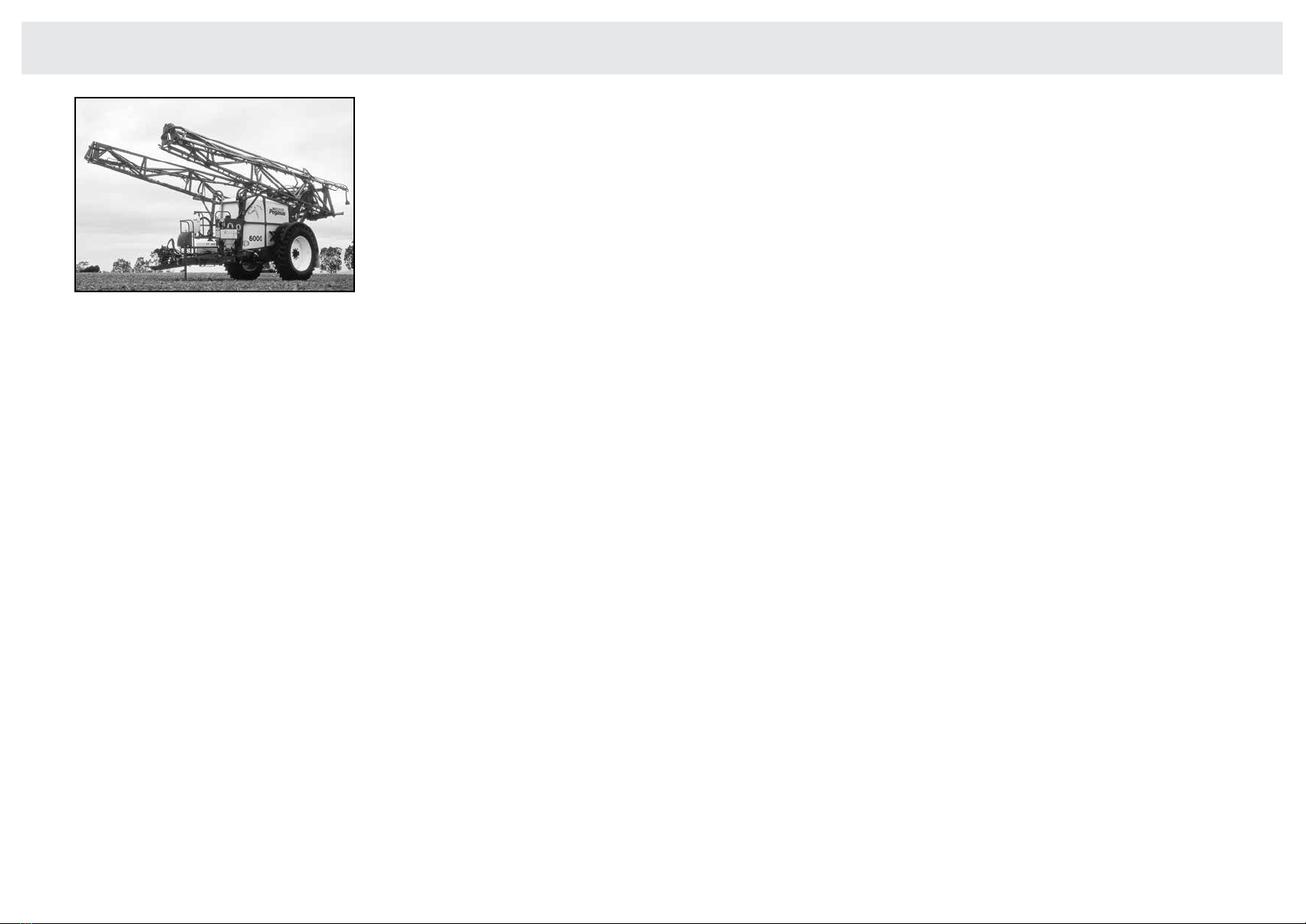
General Specications
6000 litre Pegasus with 20.8 x 42 single wheels.
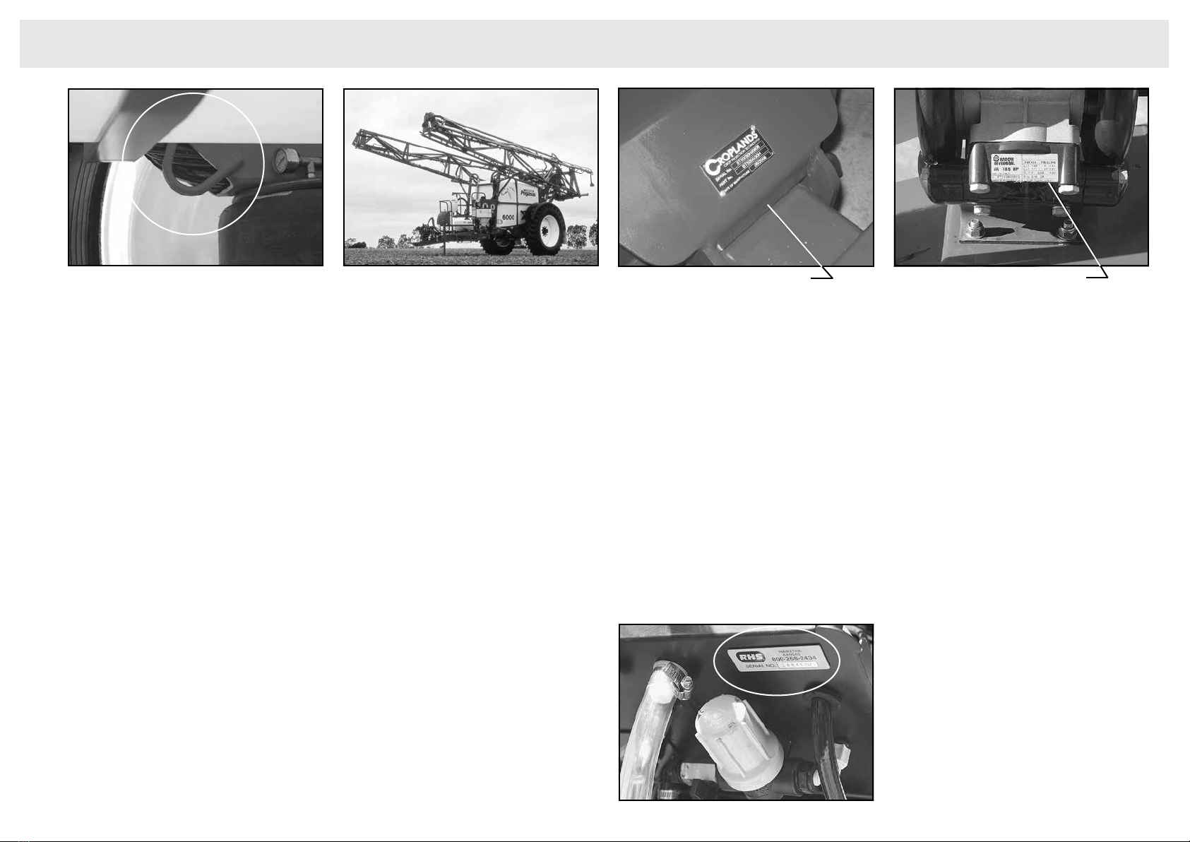
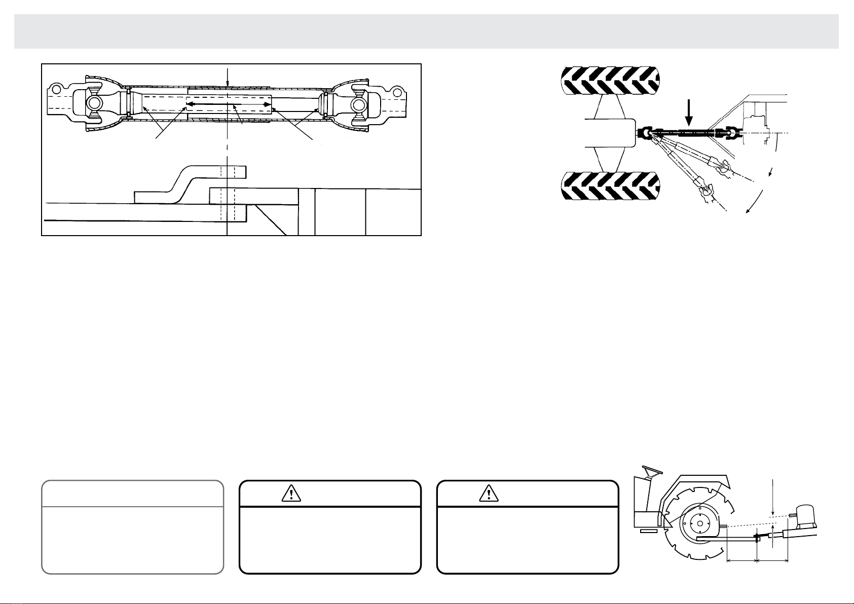
Pump
AR positive displacement oil-bath four
diaphragm pump, chemical resistant,
rated to 20 bar. Normal operating range
1 – 8 bar. Standard 185 l/min output (at
zero pressure), optional 250 & 280 l/min
pumps available. PTO drive standard,
hydraulic optional.
Filtration
Five ltration points: Basket (18 mesh),
Filling lter (32 mesh), Suction lter (50
mesh), Pressure lter (100 mesh), Nozzle
lters (50 or 100 mesh).
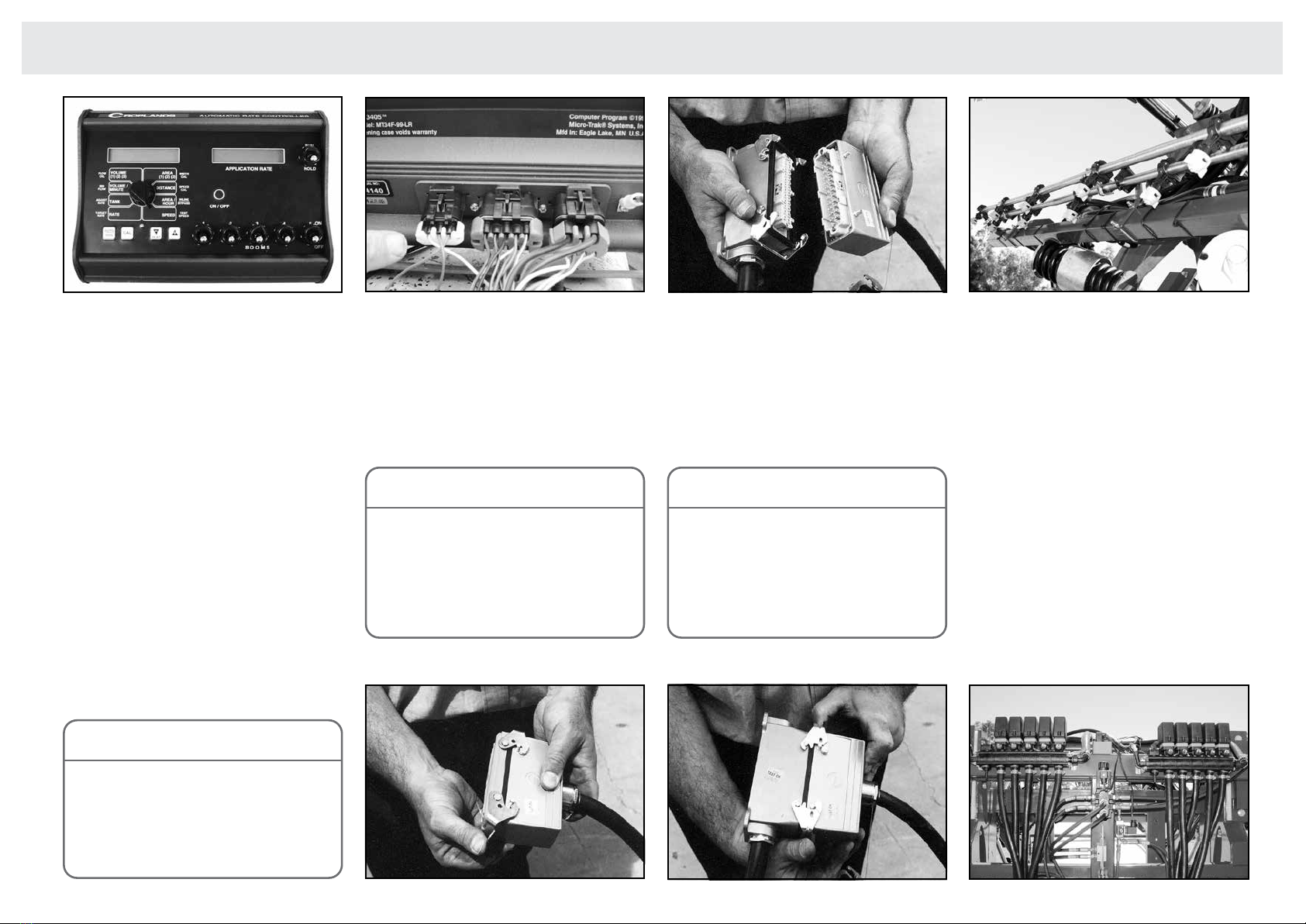
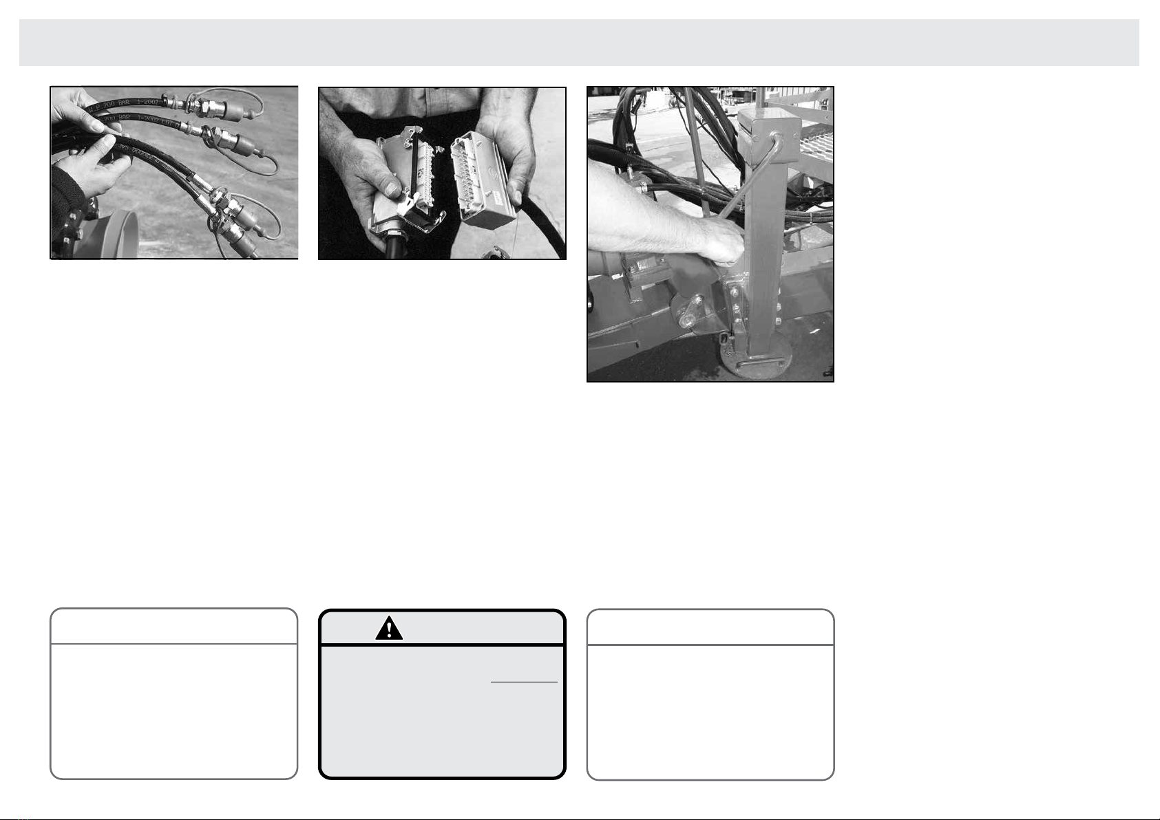
Controller & boom valves
MT3405 Microtrak fully automatic
controller tted. Three electric (motorized)
boom section valves are tted as standard
(4, 5 or 7 optional), dump & servo tted,
Polmac rapid-check owmeter with in-cab
console with switches, showing spray rate
and other functions. Optional BA7000 or
ZYNX X20 system for dual line operation.
Boom & Lift
24, 28, 30, 33 & 36 metre booms are
options (model dependent). The boom is
constructed of high quality steel in a lattice
design. Finish is in epoxy-coat paint for
chemical resistance. Outer boom wings
are tted with self-returning breakaways.
The centre boom section acts as a self-
leveler, with adjustment for anti-yaw.
Boom liquid tubing is stainless steel, with
single non-drip nozzles tted as standard.
Dual lines or triplex nozzle bodies are
optional. Boom folds hydraulically, and a
wing-lift version is offered on all models.
The parallelogram height adjuster has a
2000mm lift (2.5 metre from ground), and
is equipped with hydraulic accumulator
for boom suspension. Automatic hydraulic
boom levelling available with ZYNX X20
system controller
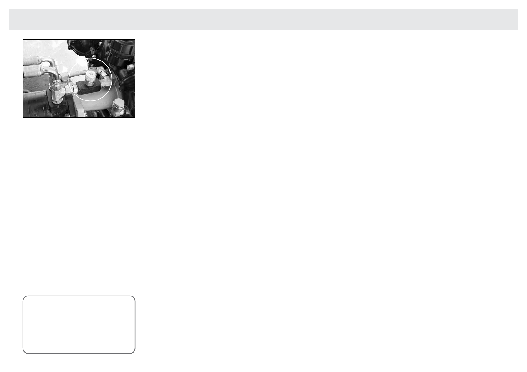
Agitation
Dual supa-ow agitators are tted. Pump
bypass also aids agitation & mixing.
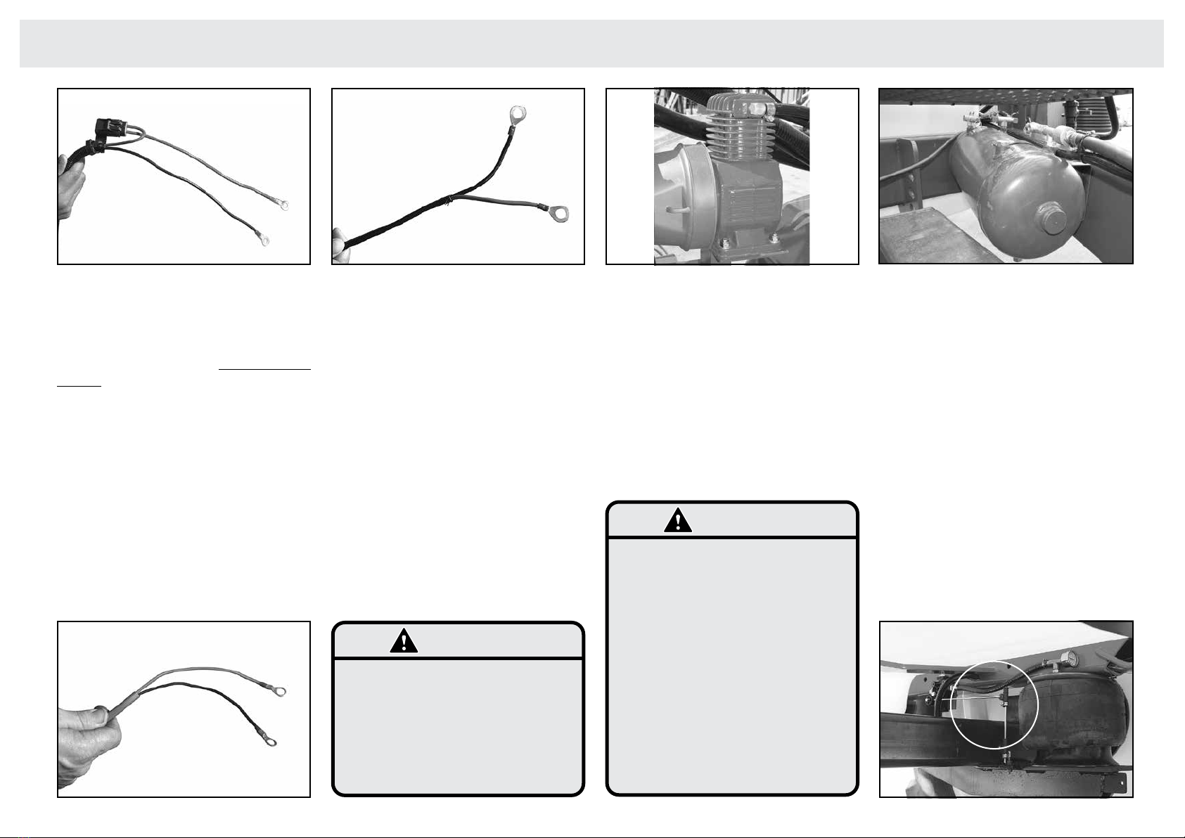
Foam Marker (if tted)
An air-compressor runs off the pump, and
feeds the air-tank, which in turn operates
the optional high-capacity Outback Foam
Marker, which has in-cab controls. A 130
litre foam concentrate tank is tted.
Chemical handling
Integrated chemical mixer/induction unit
is tted with a drop-leg device. Options
include a chemical suction probe, enviro-
transfer kit and a Dosmatic injection kit.
A 30 litre hand-wash tank is also tted
for safety.
Flushing & controls
A 340 litre ushing tank is tted, operated
from the easy-to use control panel, located
on the left hand side of the sprayer.
Options
Hydraulic pump drive, 250 or 280 l/min
pump upgrade, 4/5/7 boom sections,
dual lines, axle width adjustment kit, air-
ride axle kit, mudguards and mudaps,
BA7000 controller, Induction probe,
enviro-transfer kit, lling owmeter, foam
marker and/or GPS Guidance system,
left & right wing-lift, independent outer
wing fold kit, manual or electric fence-line
nozzles, larger wheels and tyres.
Machine specications are subject to change without
prior notication.