CAB MAESTRO 2M User manual

MAESTRO 4M
Bedienungs- und Serviceanleitung
Instructions for Use and Service
Manuel d'utilisation et de service
Ausgabe / Edition 3/07

2
Inhaltsverzeichnis
1. Produktinformation ...............................4
1.1. Allgemeines.............................................4
1.2. Gerätetypen.............................................4
2. Technische Daten..................................6
3. Lieferumfang..........................................8
4. Sicherheitshinweise..............................8
5. Aufstellung und Inbetriebnahme........10
5.1. Aufstellung.............................................10
5.2. Erdanschluss herstellen ........................10
5.3. Fußschalter montieren...........................10
5.4. Netzanschluss herstellen.......................12
5.5. Kabelxieren.........................................12
5.6. Justage des Obermessers.....................14
5.7. Justage unterer Anschlag
Obermesser...........................................18
5.8. Kontrolle der Messerstellung.................20
5.9. Einstellung Niederhalter ........................22
5.10.Einstellung des Tischs...........................22
5.11.MontageAuagetisch ............................24
6. Betrieb ..................................................26
6.1. Funktion des Fußschalters ....................26
6.2. Einschalten des Gerätes .......................26
6.3. Einstellung der Schnittlänge..................26
6.4. Einstellung der Trenngeschwindigkeit...28
6.5. Trennen der Leiterplatten ......................28
6.6. NOT-AUS-Taste.....................................30
6.7. Fehlermeldungen...................................30
7. Messerwechsel ....................................32
7.1. Wechsel Obermesser
(Rollmesser)..........................................32
7.2. Wechsel Untermesser
(Linearmesser) ......................................34
8. Ersatzteilliste (Auszug).......................36
EG-Konformitätserklärung ......................38

3
Table of Contents
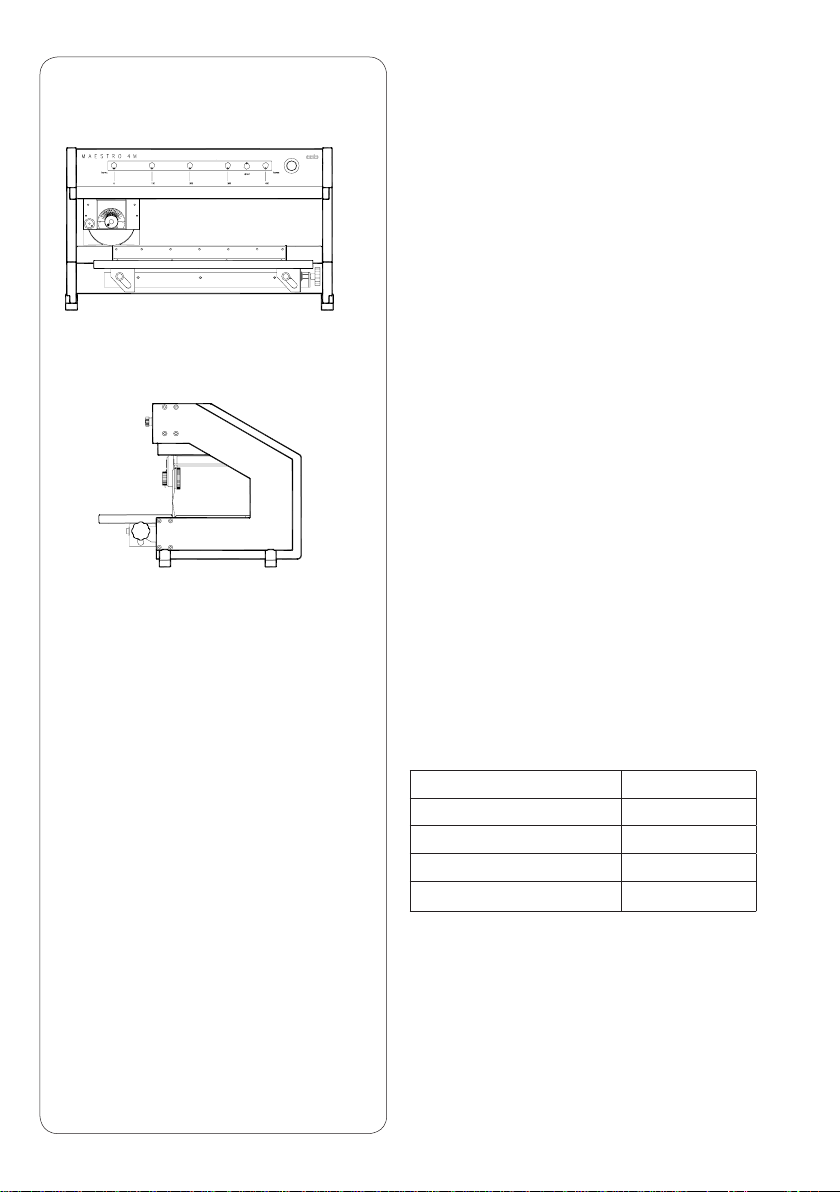
1. Product Description ..............................5
1.1. General....................................................5
1.2. Device Types...........................................5
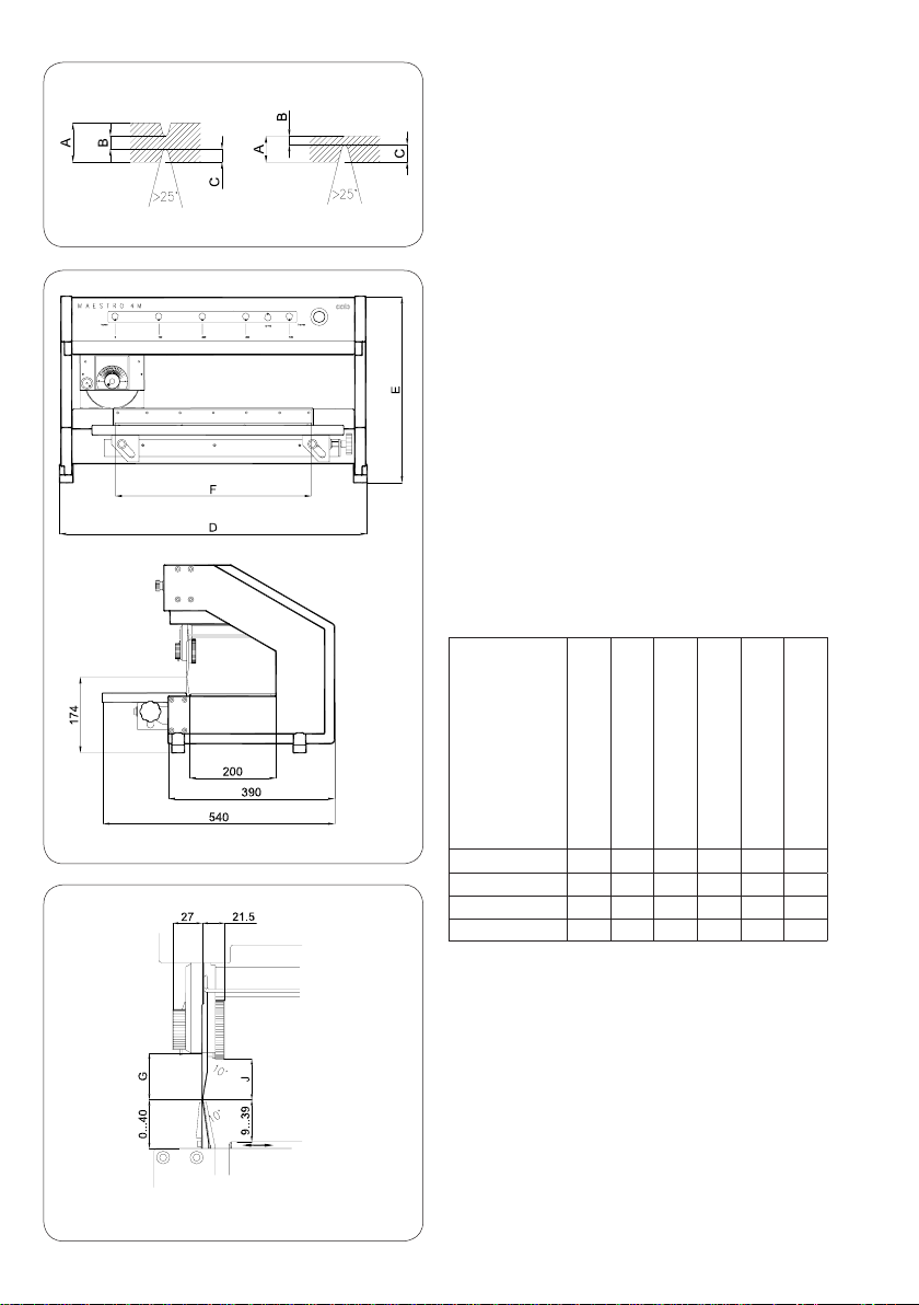
2. Technical Data........................................7
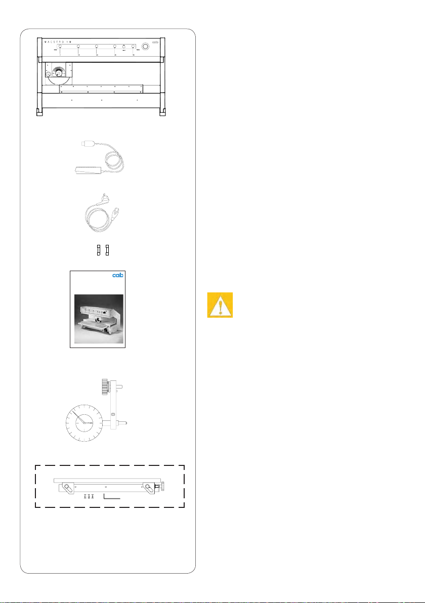
3. Contents of Delivery..............................9
4. Safety Precautions ................................9
5. Setting Up and Putting into
Operation..............................................11
5.1. Setting Up.............................................. 11
5.2. Earthing Connection.............................. 11
5.3. Connect Foot Switch .............................11
5.4. Connection to Mains Supply..................13
5.5 Attachment of Mains Cable ...................13
5.6. Height Adjustment of the Upper Blade ..15
5.7. Adjustment of the Stop of the
Upper Blade...........................................19
5.8. Check the Blade Alignment ...................21
5.9. Upper Guide Adjustment .......................23
5.10.Adjusting the Table ................................23
5.11.Assembly of the Adjustable Platform.....25
6. Operation..............................................27
6.1. Function of the Foot Switch...................27
6.2. Switching on the Machine......................27
6.3. Setting the Length of Separation...........27
6.4. Setting the Speed of Separation............29
6.5. Separating the PCB’s ............................29
6.6. Emergency Switch.................................31
6.7. Error Messages .....................................31
7. Blade Replacement..........................33
7.1. Replacement of the Upper
(Circular) Blade......................................33
7.2. Replacement of the Lower
(Lineal) Blade ........................................35
8. Replacement Parts (Extract)...............37
EC Conformity Declaration......................39
Contenu
1. Information sur le produit.....................5
1.1. Général....................................................5
1.2. Types de produits....................................5
2. Caractéristiques techniques.................7
3. Détail fourniture.....................................9
4. Conseils de sécurité..............................9
5. Installation et mise en route...............11
5.1. Installation ............................................. 11
5.2. Mise à la terre........................................ 11
5.3. Raccordement de la pédale................... 11
5.4. Branchement.........................................13
5.5. Fixerlescâbles......................................13
5.6. Ajustement du couteau supérieur..........15
5.7. Réglage de la course de blocage
du couteau supérieur.............................19
5.8. Contrôleduréglagedescouteaux.........21
5.9. Réglage des guides-cartes supérieur....23
5.10.Réglage du plateau ...............................23
5.11.Montage du plateau avant.....................25
6. Utilisation .............................................27
6.1. Fonction de la pédale ............................27
6.2. Mise sous tension..................................27
6.3. Réglage de la longueur de séparation...27
6.4. Réglage de la vitesse de séparation .....29
6.5. Séparer les cartes .................................29
6.6. Interrupteur de secours .........................31
6.7. Correction d’erreur.................................31
7. Remplacement des couteaux.............33
7.1. Remplacement et ajustage du
couteau supérieur (circulaire)................33
7.2. Remplacement et ajustage du
couteau inférieur (linéaire).....................35
8. Liste des pièces de
rechange (extrait).................................37
Déclaration de conformité CE.................39

4
1. Produktinformation
1.1. Allgemeines
Die rationelle Fertigung und das Bestücken der
Leiterplatten erfolgt meistens in Mehrfachnutzen.
Das anschließende Auseinanderbrechen der
Leiterplatten von Hand führt zu Beschädigungen
der Leiterbahnen und Bauteile. Aus den Bruch-
kanten werden Glasfaserbündel gerissen, die
Kanten sind rauh und zerklüftet.
Mit dem Nutzentrenner MAESTRO 4M werden
sowohl kleine als auch sehr große Nutzenleiter-
platten schonend und wirtschaftlich getrennt.
Die Leiterplatte wird zum Trennen mit der
Ritznut auf das Linearmesser aufgelegt. Nach
Betätigung des Fußschalters fährt der Schlitten
mit dem Rollmesser über die Leiterplatte und
trennt damit den Nutzen in Einzelplatinen. Dabei
können die Ritznuten durch Fräsungen beliebig
unterbrochen werden.
Zur Optimierung des Trennvorgangs kann die
Schnittlänge über die Bedienfeldtasten in vier
Stufen variiert werden.
Verschleißfeste Messer aus Spezialstahl sichern
lange Standzeiten ohne Nacharbeit.
1.2. Gerätetypen
Gerätetyp Art.-Nr.
MAESTRO 4M/450 8933955
MAESTRO 4M/70 8933965
MAESTRO 4M/600 8933960
MAESTRO 4M/70/520 8933905

5
1. Information sur le produit
1.1. Général
La production moderne et rationnelle, ainsi
que le montage et le test des cartes à circuits
imprimés se font de plus en plus souvent sur des
cartes pré-rainurées.
La séparation manuelle de ces cartes abîme
bien souvent les composants.
Desfaisceauxdebredeverresontarrachés,
leschampssontrugueuxvoiressurés(risque
de délaminage).
Avec le séparateur de cartes MAESTRO 4M, on
peut séparer soigneusement et à peu de frais
des petites et des très grandes cartes.
Pourséparerlescartes,ilsuftdepositionner
la rainure sur le couteau linéaire (inférieur) et
d’appuyersurlapédaleandefairepasserle
couteau circulaire (supérieur) sur la carte et ainsi
de la séparer en pièces unitaires. Les rainures
ne doivent pas obligatoirement être continues.
And’optimiserleprocessusdecoupe,lacourse
est réglable à l’aide des touches sur la machine:
4 longueurs différentes.
Lescouteauxenacierspécialontétéaffûtés
pour assurer une utilisation prolongée sans ré-
affûtage.
1. Product Description
1.1. General
For the commercially viable assembly and
mounting of printed circuit boards, there is an
ever increasing requirement for multiple-use
material. The necessity however, to break off
sections of the circuit board by hand can cause
damage to the delicate circuitry and compo-
nents.Thebre-glassmaterialtearsatthe
brokenedge,leavingitroughandssured.
Using the MAESTRO 4M, both large and small
pre-scored PCB’s can be cleanly and economi-
cally separated. The PCB to be separated is laid
onto the lineal blade in such a way that the edge
of the blade locates into the pre-scored groove
in the PCB. When the foot-switch is operated
the carrier assembly holding the circular blade
is drawn across the PCB, separating it into
individual pieces. The scored groove can be
interrupted by any number of cut-outs. In order
to ensure that the separation is performed in the
optimalmanner,veprogrammingkeysenable
the length of separation to be varied in four
stages.
Wear resistant blades and a guide assembly
manufacturedfromspecialsteelensuremaxi-
mum periods between readjustments.
1.2. Device Types
Device type Part No.
MAESTRO 4M/450 8933955
MAESTRO 4M/70 8933965
MAESTRO 4M/600 8933960
MAESTRO 4M/70/520 8933905
1.2. Types des produits
Type des produits N° d’article
MAESTRO 4M/450 8933955
MAESTRO 4M/70 8933965
MAESTRO 4M/600 8933960
MAESTRO 4M/70/520 8933905

6
2. Technische Daten
Linear- und Rollmesser
gehärtet und geschliffen
Leiterplattendicke A 0,8 bis 3,2 mm
Vergrößerung der Außenmaße
nach dem Trennen 0,1 bis 0,2 mm
Empfohlene Restdicke B 1/3 von Maß A
min.0,25mm,max.0,8mm
Ritztiefe C min. 0,25 mm
Geschwindigkeit 2 Stufen
Netzspannung 230/115 V~ - 50/60 Hz
Erdung Druckknopf ø 10 mm
Betriebstemperatur 15 bis 25°C
Lager- und Transporttemperatur -20 bis 50°C
Luftfeuchte 10 bis 85% nicht kondensierend
NOT-Aus-Schalter
Maße
Gerätelänge
Gerätehöhe
Trennlänge
Bauteilhöhe
vor Trennkante
Bauteilhöhe
hinter Trennkannte
Gewicht
Typ D E F G J
mm mm mm mm mm kg
M’4M/450 702 434 450 40 34 38
M’4M/70 702 492 370 70 64 40
M’4M/600 852 434 600 40 34 46
M’4M/70/520 852 492 520 70 64 48
Zulassungen
GS-Zeichen erteilt
CE:Schutzanforderungen der
- EG-Maschinenrichtlinie (89/392/EWG)
- EG-Niederspannungsrichtlinie (73/23/EWG)
- EG-Richtlinie Elektromagnetische
Verträglichkeit (89/336/EWG)

7
2. Caractéristiques techniques
Couteaux (linéaire et circulaire)
durcisetaffûtés
Epaisseur des cartes A 0,8 - 3,2 mm
Tolérance à prévoir lors du design des cartes
+ 0,1 à 0,2 mm
Epaisseur résiduelle conseillée B
1/3 de la valeur A
min.0,25mm,max.0,8mm
Epaisseur des rainure C min. 0,25 mm
Vitesse de séparation 2 marches
Alimentation 230/115 V - 50/60 Hz
Mise à la terre câblebutonØ10mm
Température d’utilisation 15 à 25°C
Température de stockage et de transport
-20 à +50°C
Humidité 10 à 85% HR
Interrupteur de secours
Dimensions
Longueur
Hauteur
Longueur de coupe
Hauteurmax.descomp.
devant le couteau
Hauteurmax.descomp.
derriere le couteau
Poids
Type D E F G J
mm mm mm mm mm kg
M’4M/450 702 434 450 40 34 38
M’4M/70 702 492 370 70 64 40
M’4M/600 852 434 600 40 34 46
M’4M/70/520 852 492 520 70 64 48
Certicats
CerticatGS
CE:exigencesdeprotectionselon
- lignes directrices pour les machines (89/392/CEE)
- lignes directrices pour la tension (72/23/ CEE)
- lignes directrices pour la compatibilité
électro-
magnétique (
89/336/CEE)
2. Technical Data
Lineal and Circular Blades
hardened and polished
PCB Thickness A 0.8 - 3.2 mm
Increase of External Dimensions
following Separation 0.1 - 0.2mm
Thickness of Material Remaining B
after pre-scoring 1/3 from measure A
min.0.25mm,max.0.8mm
Depth of the slot C min. 0.25 mm
Separation Speed 2 levels
Power Supply 230/115v - 50/60 Hz
Earthing 10mm dia. press-stud
Operating Temperature
15°C- 25°C (59°F-77°F)
Storage / Transport Temp.
-20°C- 50°C (-4°F-122°F)
Humidity 10% - 85% non-condensing
Emergency Switch
Dimensions
Device Length
Device Height
Sep. Length
Comp. Height in
front of sep. edge
Comp. Height in
behind sep. edge
Weight
Type D E F G J
mm mm mm mm mm kg
M’4M/450 702 434 450 40 34 38
M’4M/70 702 492 370 70 64 40
M’4M/600 852 434 600 40 34 46
M’4M/70/520 852 492 520 70 64 48
Approval Certicates
CerticateGS
CE:Protection Requirements as according to:
- EC Machinery Directive (89/392/EEC)
- EC Low-Voltage Directive (73/23/EEC)
- EC Electromagnetic Compatibility
Directive (89/336/EEC)

8
3. Lieferumfang
Nutzentrenner MAESTRO 4M
Fußschalter
Netzkabel
2 Sicherungen 1,6 AT
(für Betrieb bei 115 V)
Bedienungsanleitung
als Option :
Messeinrichtung Art.-Nr. 8970208
(zur Kontrolle der Messerstellung)
Auagetisch
komplett mit :
3ZylinderschraubenM5x12,
3 Scheiben A5.3,
Sechskantschlüssel 4mm
1–
2–
3–
4–
5–
6–
7–
1
6
7
2
3
4
5
4. Sicherheitshinweise
ACHTUNG !
Das Gerät ist ausschließlich zum Trennen
vorgeritzter Leiterplatten zu benutzen.
Jede andere Verwendung des Gerätes ist
unzulässig !
Eingriffe am Gerät, die über die in dieser
Bedienungsanleitung beschriebenen Hand-
lungen hinausgehen, sind nur von autorisier-
tem Personal durchzuführen.
Beim Trennen der Leiterplatten sind Schutz-
handschuhe zu tragen.
Während des Betriebs ist darauf zu achten,
dass Schmuckstücke, lose Kleidung, Haare
u.ä. aus dem Bereich der Messer ferngehal-
ten werden.
Betätigen Sie im Gefahrenfall die rote NOT-
AUS-Taste.DiesebendetsichimBedienfeld
an der Vorderseite des Gerätes. Dadurch
wird die Spannungszufuhr zum MAESTRO
4M unterbrochen (siehe Pkt. 6.6.).
1.
2.
3.
4.
5.
MAESTRO 4M
Bedienungs- und Serviceanleitung
Instructions for Use and Service
Manuel d’utilisation et de service
Ausgabe / Edition 2/07

9
3. Détail fourniture
Séparateur de cartes MAESTRO 4M
Pédale
Câbled’alimentation
2 fusibles 1,6 A
(pour utilisation éventuelle en 115 V)
Manuel d’utilisation
En option :
Comparateur N° d‘article 8970208
(pourcontrôlerleréglagedescouteaux)
Plateau avant réglable
livré avec:
3vissix-pans-creuxM5x12
3 rondelles A5.3
1cléhexagonalede4mm
1–
2–
3–
4–
5–
6–
7–
3. Contents of Delivery
PCB Separator MAESTRO 4M
Foot Switch
Mains Cable / Power Cord
2 Fuses rated 1.6 AT
(for operation from 115v)
Instructions for Service and Use
Optional Accessory :
Dial Gauge Assy. Part No. 8970208
(to check the alignment of the blades)
Adjustable Platform
incl.:
3CylinderScrewsM5x12
3 Washers A5.3
Allen Key 4mm.
1–
2–
3–
4–
5–
6–
7–
4. Safety Precautions
CAUTION !
The machine may only be used to separate
pre-scored PCB’s. Use for any other purpose
is not allowed !
Any adjustments or further work on the MAE-
STROwhichexceedthosedescribed
in this handbook may only be performed by
authorised personnel.
When separating PCB’s, suitable protective
gloves should be worn.
During operation ensure that all loose hang-
ing items, eg. Jewelry, Clothing, Hair etc., are
kept well clear of the blades.
In an emergency situation, actuate the
emergency stop switch by tight pressing. The
emergency switch is located in the front panel
of the device. By pressing this switch the volt-
age supply is interrupted. (see chapter 6.6.).
1.
2.
3.
4.
5.
4. Conseils de sécurité
ATTENTION !
L’appareilestexclusivementfaitpourséparer
des cartes pré-rainurées.
Toute autre utilisation est déconseillée !
Seules les personnes autorisées peuvent
utiliser, ajuster ou réparer la machine confor-
mémentauxconseilsdonnésci-après.
Toujours porter des gants de protection lors
de la séparation des cartes.
Pendant l’utilisation toujours prendre garde
auxbijoux,vêtementsoucheveux,etc...qui
risqueraientdeseprendredanslescouteaux.
Au front du MAESTRO 4M se trouve un
interrupteur de secours (rouge). Dans une
situation critique presser l'interrupteur et le
branchement de la machine est coupé. (c.f.
Para. 6.6.).
1.
2.
3.
4.
5.

10
2
3
5. Aufstellung und
Inbetriebnahme
5.1. Aufstellung
Der Nutzentrenner MAESTRO 4M ist nach
der Aufstellung auf einer ebenen Unterlage mit
wenigen Handgriffen einsatzbereit.
Bei der Erstinbetriebnahme ist es günstig, die
Messer mit einem weichen Tuch zu entfetten.
5.2. Erdanschluss herstellen
Zur Herstellung des Erdanschlusses ist am
Gerät ein Druckknopf mit dem Durchmesser
10mm (9) angebracht.
Der Erdanschluss ist notwendig, da es beim
Trennen von Leiterplatten zu elektrostatischen
Auadungenkommenkann.
5.3. Fußschalter montieren
Schließen Sie das Fußschalterkabel (2) an der
Buchse (8) neben dem Netzeingangsmodul an.
8
9

11
5. Setting Up and Putting into
Operation
5.1. Setting Up
Once the MAESTRO 4M PCB Separator has
beenplacedonarmsurface,itcanbeputinto
operation with a minimum of effort.
Whenusingthemachineforthersttime,itwill
be found that both blades are covered with a
protectivelmofoil.Thiscanberemovedby
wiping it off with a soft cloth.
5.2. Earthing Connection
To provide an earthing connection a 10mm dia.
press stud (9) is mounted on the machine frame.
A connection to earth is necessary due to the
build-up of electrostatic charges which can occur
when PCB’s are separated.
5.3. Connect Foot Switch
Connect the foot switch cable (2) to the socket
(8) adjacent to the mains input module.
5. Installation et mise en route
5.1. Installation
Une fois le MAESTRO 4M sorti de son embal-
lage, l’installer sur une surface plane.
La mise en route se fait selon les indications qui
suivent et peu de manipulations sont néces-
saires. Lors de la première mise en route, il est
recommandé de retirer la graisse qui se trouve
surlescouteauxàl’aided’unchiffondoux.
5.2. Mise à la terre
Pour relier la machine à la terre, utiliser le bou-
ton pression (9) de 10mm de diamètre, à l’arrière
de la machine.
La mise à la terre est nécessaire car des déchar-
ges électrostatiques peuvent avoir lieu lors de la
séparation des cartes.
5.3. Raccordement de la pédale
Brancherlecâbledelapédale(2)àlaprise(8)
prévue à cet effet, à côté du module de branche-
ment.

12
5.4. Netzanschluss herstellen
Überprüfen Sie die Einstellung der Betriebs-
spannung am Spannungswähler (11). Zur
Änderung der Einstellung öffnen Sie die
Klappe (10) am Netzmodul. Setzen Sie den
Spannungswähler so ein, dass die aktuelle
Betriebsspannung im Fenster der Klappe
ablesbar ist. Bei Änderung der Einstellung
sind die Sicherungen zu wechseln (800mAT
bei 230V; 1,6AT bei 115 V).
Schließen Sie das Gerät über das mitgeliefer-
te Netzkabel (3) an eine geerdete Steckdose
an.
Falls das Gerät nach dem Einschalten keine
Funktion zeigt, überprüfen Sie sowohl die
Sicherungen im Netzmodul als auch die Si-
cherung der Ansteuerelektronik (4AT) (14).
NebendemNetzmodulbendetsicheine
Buchse (15) zur Spannungsversorgung für
ein optionales Transportband.
Jede anderweitige Nutzung dieses An-
schlusses (15) ist unzulässig !
5.5. Kabel xieren
Befestigen Sie das Netzkabel (3) sowie das
Kabel des Fußschalters (2) entsprechend dem
nebenstehenden Bild mit den Kabelhaltern (16)
an der Innenseite des Gestells.
1.
2.
3.
4.
5.
16
2
3
16
9
15
10
11
12
13
14

13
5.4. Connection to Mains Supply
Check the setting of the voltage selector (11)
and if necessary alter it as follows:
Openthemoduleap(10),removeandre-
place the voltage selector so that the correct
voltage setting is visible when the module
apisclosed.
Upon altering the input voltage setting, the
fuse must also be changed accordingly,
(800mAT for 230v, 1.6AT for 115v).
Using the mains cable / power cord (3)
supplied, connect the machine to the mains
supply via an earthed socket.
If the machine does not show any function
after it has been switched on, please check
the fuses of the mains module and the fuse
(4AT) (14) of the electronics board.
Nexttothemainsmodulethereisapower
socket (15) for an optional conveyor belt.
Any other use of this socket (15) is inadmis-
sible !
5.5. Attachment of Mains Cable
(Power Cord)
Attach the mains supply cable (3) and the cable
(2) from the foot-switch in the manner shown in
the illustration, using the cable fasteners (16) on
the inner side of the machine frame.
1.
2.
3.
4.
5.
5.4. Branchement
Vérierleréglagedelatensionélectriqueà
l’aide de l’indicateur de tension (11) et la mo-
diersinécessaire.Pourcela,ouvrirlerabat
(10) sur le module de branchement et ajuster
le voltage de manière à ce que lorsque le
rabat est replacé sur le module, le voltage dé-
siré apparaisse dans la fenêtre du rabat. Lors
du changement de voltage, ne pas oublier de
changer les fusibles (800 mA pour 230 V; 1,6
A pour 115 V).
Brancherlecâbled’alimentation(3)fourni
avec la machine dans le module de branche-
ment et le connecter à une prise reliée à la
terre.
Dans le cas où lors de sa mise sous tension,
lamachineneréagitpas,vérierlesfusibles
du module de branchement, ainsi que celui
de la carte électronique (4A) (14).
Auprès du module de branchement se trouve
une prise (15) pour le branchement d'un
convoyeur à bande optionnel.
Toute autre utilisation de la prise (15) est
déconseillée !
5.5. Fixer les câbles
Fixerlecâbled’alimentation(3)ainsiquele
câbledelapédale(2)lelongdelaparoidubâti,
dans les supports prévus à cet effet (16), confor-
mément au schéma ci-joint.
1.
2.
3.
4.
5.

14
17a 17b 5.6. Justage des Obermessers
Das Obermesser (23) ist in der Höhe verstellbar.
Um Schäden während des Transportes zu
vermeiden,bendetsichdasObermesserim
Auslieferungszustand in der obersten möglichen
Position. Daher ist es notwendig, das Obermes-
ser bei der Inbetriebnahme in die Arbeitsposition
zu stellen :
Hebel (17) in Stellung a schwenken.
Dadurch wird der Motor aus dem Getriebe
des Schlittens (20) ausgekuppelt.
Schlitten (20) etwa bis zur Mitte des Unter-
messers (24) schieben.
Auf dem Schlitten des Obermessers ist eine
Skala (21) angebracht, an der die Höhenein-
stellung des Messers in 1/10mm ablesbar ist.
Bei Lieferung steht der Zeiger (22) in Stellung
"16".
Lösen Sie zur Verstellung des Obermessers
die Rändelmutter (19). Halten Sie dabei den
Einstellknopf (18) fest.
Drehen Sie den Einstellknopf (18) bis zum
Anschlag im Uhrzeigersinn. Dadurch wird das
Obermesser (23) soweit nach unten bewegt,
dass es das Untermesser (24) minimal
berührt (untere Endposition). Halten Sie die
erreichte Stellung des Zeigers (22) als Aus-
gangsstellung für weitere Justagen fest.
Der Verstellweg des Obermessers ist hier
begrenzt, um ein Übereinanderfahren der
Messer zu verhindern.
Drehen Sie den Einstellknopf (18) entgegen
dem Uhrzeigersinn etwa bis zur Mitte zwi-
schen unterer Endstellung und Stellung "16".
1.
2.
3.
4.
5.
6.
18 19
20 21 22
18 23 24

15
5.6. Ajustement du couteau supérieur
Lors de la livraison du MAESTRO 4M, le
couteau supérieur (23) est réglé de telle sort
quel'écartentrelescouteauxsoitleplusgrand
possible pour éviter toute dégradation des
couteauxpendantletransport.C'estpourquoi,
il est nécessaire de mettre le couteau supérieur
en position de travail pour mettre la machine en
route:
Tourner le levier de blocage (17) dans la
position "a". Le moteur est ainsi débrayé du
couteau supérieur.
Pousser le support du couteau supérieur (20)
jusqu’au milieu du couteau linéaire (24).
Sur le support du couteau supérieur, il y a
une graduation (21) sur laquelle la hauteur du
couteau est lisible au 1/10ème.
Lors de la livraison, l'aiguille (22) se trouve
sur «16».
Pour régler le couteau supérieur, dévisser
l'écrou (19) tout en maintenant la vis de
réglage (18).
Tourner la vis de réglage (18) dans le sens
des aiguilles d'une montre jusqu'à ce qu'elle
soit bloquée. Cela va déplacer le couteau
supérieur (23) vers le bas jusqu'à frôler le
couteau inférieur (24), position inférieur
maximum.Regardersurlagraduation(21)la
position indiquée par l'aiguille (22) et retenir
comme la position la plus basse pour les
réglages futurs.
La course permettant la descente du couteau
supérieur est ici limitée pour éviter que les
couteauxnesetouchentounesebloquent.
Tourner la vis de réglage (18) dans le sens
inverse des aiguilles d'une montre jusqu'à mi-
cheminentrelapositioninférieuremaximum
et la position d'attente «16».
1.
2.
3.
4.
5.
6.
5.6. Height Adjustment of the Upper Blade
To avoid possible damage on the blades during
transporttheupperblade(23)isxedinthe
"ParkPosition"sothatthereisamaximum
distance to the lower blade. Therefore the upper
blade has to be set into the working position
before switching on the machine :
Move the lever (17) to the position 'a'.
The motor drive to the blade carrier (20) is
now disconnected.
Movethebladecarrier(20)totheapproxi-
mate middle position over the lower blade
(24).
There is a scale (21) on the upper blade car-
rier where you can see the height adjustment
in steps of 1/10 mm. When you receive the
machine, the pointer (22) of the scale is in
position "16".
To adjust the upper blade loosen the knurled
knob (19) and hold the knob (18).
Rotate the knob (18) in a clockwise direction
until stop. Through that the upper blade (23)
move down to the lower blade (24) until both
blades are just touching one another (lower
end position). Make a notice of the position of
the pointer (22) to use it for all further adjust-
ments.
This lower end position locks the upper blade
in place to prevent it from moving out of
adjustment.
Move the knob (18) in the anti-clockwise
direction until the pointer is in the middle posi-
tion between the lower end position and the
position "16".
1.
2.
3.
4.
5.
6.

16
17a 17b
18 19
Ziehen Sie die Rändelmutter (19) an und
überprüfen Sie mit Testschnitten, ob sich
die Leiterplatten vollständig trennen lassen.
Wenn dies nicht der Fall ist, verringern Sie
den Messerabstand in kleinen Schritten.
Die beschriebene Justagemethode ermög-
licht eine Minimierung der mechanischen
Spannungen beim Trennen der Leiterplatten.
Dies ist besonders wichtig, wenn sich emp-
ndlicheBauelementeinunmittelbarerNähe
derRitznutbenden.
FürbesondersempndlicheLeiterplatten
lässt sich der MAESTRO 4M im Doppelweg-
verfahren betreiben. Für diesen Einsatzfall
kann der Messerabstand so groß gewählt
werden, dass die Leiterplatten erst beim
zweiten Überfahren getrennt werden.
Nach beendeter Justage Hebel (17) in
Stellung b schwenken und Motor wieder
einkuppeln.
7.
8.
9.

17
Tighten the knurled knob (19) and run some
test-cuts to check if it is possible to separate
the PCB's. If it is not possible reduce the
distance between the blades in small steps.
The described adjustment helps to reduce
the separation forces. This is important when
sensitive components are very close to the
groove.
If there are very sensitive components on the
PCB it is also possible to use the machine in
a double-way method. In this case the dis-
tance between the blades can be increased
that the PCB's will be separated by "go over
twice".
Move the lever (17) to the position 'b'.
The motor drive to the blade carrier (20) is
now reconnected.
7.
8.
9.
Revisserl’écroue(19)etvérierenfaisantun
test de séparation que les cartes sont bien
séparées. Si cela n'est pas le cas, réduire
l'écartentrelescouteauxpetitàpetit.
Le mode d'ajustage décrit ci-dessus permet
de minimaliser les tensions mécaniques lors
de la séparation des cartes. Ceci est particu-
lièrement important quand des composants
sensibles se trouvent près de la rainure.
Quand les composants sont très sensibles
il est aussi possible d'utiliser la machine en
«aller-retour». Dans ce cas on peut hausser
l'écartentrelescouteauxjusquelasépara-
tionalieuavecdeuxpassages.
Mettre le levier de blocage (17) dans la posi-
tion "b", de manière à ré-embrayer le moteur
au couteau supérieur.
7.
8.
9.

18
5.7. Justage unterer Anschlag
Obermesser
Die untere Begrenzung des Verstellweges für
das Obermesser ist bei Auslieferung des Ge-
rätes justiert.
Nach längerer Benutzung, bei großen Tempe-
raturschwankungen oder nach einem Messer-
wechsel ist es sinnvoll, den unteren Anschlag
neu einzustellen :
Hebel (17) in Stellung a schwenken.
Dadurch wird der Motor aus dem Getriebe
des Schlittens (20) ausgekuppelt.
Schlitten mit Obermesser (23) in die Mitte des
Untermessers schieben.
Rändelmutter (19) lösen. Einstellknopf (18)
dabei festhalten.
Einstellknopf (18) entgegen dem Uhrzeiger-
sinn bis zum Anschlag drehen (Zeiger (22) in
Stellung "16").
Zylinderschraube (25) lösen.
Einstellknopf (18) im Uhrzeigersinn drehen,
bis sich Ober- und Untermesser leicht berüh-
ren, ohne zu verklemmen.
Einstellknopf festhalten und Rändelmutter
(19) anziehen.
Hebel (26) bis zum Anschlag im Uhrzeiger-
sinn schwenken und Zylinderschraube (25)
anziehen. Mit dieser Einstellung wird der
Verstellweg des Obermessers nach unten
begrenzt und ein versehentliches Übereinan-
derfahren der Messer ausgeschlossen.
Nach beendeter Justage Hebel (17) in
Stellung b schwenken und Motor wieder
einkuppeln.
1.
2.
3.
4.
5.
6.
7.
8.
9.
18 22
262523
17a 17b
20
18 19

19
5.7. Adjustment of the Stop of the
Upper Blade
The lower stop of the adjustment of the upper
blade is already adjusted by delivery.
After a long operation time, while working at
strongly varying temperatures or else after
replacing a blade, it is recommended to re-adjust
the lower stop :
Move the lever (17) to the position 'a'.
The motor drive to the blade carrier (20) is
now disconnected.
Move the upper blade carrier (23) in the
middle position of the lower blade.
Loosen the knurled knob (19) and hold the
knob (18) at the same time.
Rotate the knob (18) in the anti-clockwise
direction until reach the stop (pointer (22) in
position "16").
Loosen the cylinder screw (25).
Move the knob (18) in the clockwise direction
until the upper and lower blades gently touch
without overlapping.
Hold tight the knob (18) and tighten the
knurled knob (19).
Swing the strut (26) in the clockwise direc-
tion until you reach the stop and tighten the
cylinder screw (25). This adjustment locks the
upper blade in place to prevent it from moving
out of adjustment.
Move the lever (17) to the position 'b'.
The motor drive to the blade carrier (20) is
now reconnected.
1.
2.
3.
4.
5.
6.
7.
8.
9.
5.7. Réglage de la course de blocage
du couteau supérieur
La limite inférieur de la course du couteau
supérieur est déjà réglée lors de la livraison de
la machine. Après une utilisation prolongée, lors
d'écarts de température importants ou après le
remplacement d'un couteau, il est utile de re-
régler la limite inférieur de la course du couteau
supérieur :
Tourner le levier de blocage (17) dans la
position "a". Le moteur est ainsi débrayé du
couteau supérieur.
Pousser le support du couteau supérieur (23)
jusqu'au milieu du couteau inférieur.
Dévisser l'écrou (19) en maintenant la vis de
réglage (18).
Tourner la vis de réglage (18) dans le sens
inverse des aiguilles d'une montre jusqu'à ce
qu'il se bloque (l'aiguille (22) indique «16»).
Desserrer la vis de maintien (25).
Tourner la vis de réglage (18) dans le sens
des aiguilles d'une montre jusqu'à ce que le
couteau supérieur entre en contact avec le
couteau inférieur, ils doivent se frôler, ils ne
doivent pas se bloquer.
Revisser l’écrou (19) en maintenant la vis de
réglage (18).
Faire pivoter le levier (26) dans le sens des
aiguilles d'une montre jusqu'au blocage et
resserrer la vis de maintien (25).
Ce réglage permet de limiter la course du
couteau supérieur vers la bas et d'éviter
quelescouteauxnesetouchent,lorsquele
couteau supérieur se déplace sur le couteau
inférieur.
Mettre le levier de blocage (17) dans la posi-
tion "b", de manière à ré-embrayer le moteur
au couteau supérieur.
1.
2.
3.
4.
5.
6.
7.
8.
9.

20
5.8. Kontrolle der Messerstellung
Bei der Inbetriebnahme, nach einem Standort-
wechsel sowie nach einem Messerwechsel ist
es vorteilhaft, die Stellung der beiden Messer
zueinander zu überprüfen. Dazu wird eine
Messeinrichtung (Art.-Nr. 8970208) als Option
angeboten.
Hebel (17) in Stellung a schwenken.
Dadurch wird der Motor aus dem Getriebe
des Schlittens (20) ausgekuppelt.
Schlitten (20) in die Mitte des Gestells schie-
ben.
Messeinrichtung mit Rändelschraube (29)
an der Gewindebohrung (27) im Schlitten
befestigen.
Es ist darauf zu achten, dass der im Hebel
(31)bendlicheStift(30)indieBohrung(28)
am Schlitten greift.
Hebel (31) so weit nach oben schwenken,
dass die Spitze der Messuhr (32) 2 mm vom
Messerrand entfernt gegen das Obermes-
ser (23) drückt. Skalenring der Messuhr so
drehen, dass der Zeiger der 1/100mm-Teilung
auf die "0" der Skala zeigt.
Hebel (31) so weit nach unten schwenken,
dass die Spitze der Messuhr (32) 2 mm
unterhalb der Messeroberkante gegen das
Untermesser (24) drückt.
Der so gemessene Wert darf beim Verschie-
ben des Schlittens (20) über den gesamten
BereichdesUntermessersummaximal
±0,1mm von dem am Obermesser ermittelten
Messwert abweichen.
Sollte der gemessene Versatz zwischen
Ober- und Untermesser größer als ±0,1mm
sein, ist die zuständige Servicestation zu
verständigen.
Hebel (17) in Stellung b schwenken und
dadurch Motor wieder einkuppeln.
1.
2.
3.
4.
5.
6.
7.
29
32
31
23
24
17a 17b
20
27
28
29
31 32
30
Other manuals for MAESTRO 2M
2
Table of contents
Other CAB Industrial Equipment manuals
Popular Industrial Equipment manuals by other brands

3M
3M 3M-Matic 120af3 Instructions and parts list

Leroy-Somer
Leroy-Somer unidrive sp Installation and commissioning manual

HEIDENHAIN
HEIDENHAIN ERN 1323 Mounting instructions

Smartflow
Smartflow FasTie installation instructions

Vimpex
Vimpex hydrosense HSHWI-100 installation instructions

Martin
Martin Tracker Series installation manual