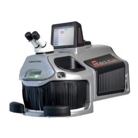
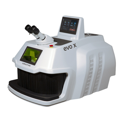
OROTIG EVO White User manual

MAN00077-02-EN
LASER welder
Operator Manual
This equipment has been designed in accordance with IEC 61010-1 and IEC 60825-1 safety regulations to prevent operator accidents
if correctly and properly used.However, no engineering design can make this equipment safe if it is not used and maintained with
due care and according to standards. This manual must be carefully and thoroughly read before performing any operation. Failure
to follow the instructions and safety regulations can cause damage to the operator and to the equipment.

MAN00077-02-EN
Contents
General information......................................................................................................................................................................................4
Identification.........................................................................................................................................................................................................................................................................................4
Safety information ........................................................................................................................................................................................5
General safety rules..........................................................................................................................................................................................................................................................................5
Protections.............................................................................................................................................................................................................................................................................................7
Interlock contact.........................................................................................................................................................................................................................................................................7
Leather barrier.............................................................................................................................................................................................................................................................................7
Resonator shutter......................................................................................................................................................................................................................................................................7
Infra-red microscope filter....................................................................................................................................................................................................................................................8
Welding chamber infra-red filter......................................................................................................................................................................................................................................8
E me r ge n cy bu tton.....................................................................................................................................................................................................................................................................8
Enabling key/PIN........................................................................................................................................................................................................................................................................8
Hazardous areas and residual risks.........................................................................................................................................................................................................................................8
General rules.................................................................................................................................................................................................................................................................................8
Before all use of the equipment........................................................................................................................................................................................................................................8
Transportation precautions..................................................................................................................................................................................................................................................8
Packaging precautions............................................................................................................................................................................................................................................................9
Installation ................................................................................................................................................................................................. 11
Transport...............................................................................................................................................................................................................................................................................................11
Unpacking.............................................................................................................................................................................................................................................................................................11
Positioning............................................................................................................................................................................................................................................................................................11
Preliminary checks............................................................................................................................................................................................................................................................................11
Electric connection..........................................................................................................................................................................................................................................................................12
Power supply tolerances......................................................................................................................................................................................................................................................12
Equipment specifications.............................................................................................................................................................................13
Technical specifications................................................................................................................................................................................................................................................................13
Applied Standards and Directives:.................................................................................................................................................................................................................................13
Intended use.......................................................................................................................................................................................................................................................................................13
Non-declared uses..........................................................................................................................................................................................................................................................................14
Labels and safety devices:...........................................................................................................................................................................................................................................................14
Op e r at o r in te r face ...................................................................................................................................................................................... 16
Controls and signals.......................................................................................................................................................................................................................................................................16
Rear connections.............................................................................................................................................................................................................................................................................16
Use............................................................................................................................................................................................................17
Recommendations..........................................................................................................................................................................................................................................................................17
Positioning and ergonomics......................................................................................................................................................................................................................................................17
Microscope eye pieces.........................................................................................................................................................................................................................................................17
Turning on the equipment.........................................................................................................................................................................................................................................................17
Emergency stop................................................................................................................................................................................................................................................................................17
Using the LASER welder...............................................................................................................................................................................................................................................................17
Display.......................................................................................................................................................................................................18
Stand-by Menu.........................................................................................................................................................................................................................................................................18
Options Menu............................................................................................................................................................................................................................................................................18
Sanitisation...................................................................................................................................................................................................................................................................................19
Work session..............................................................................................................................................................................................................................................................................20

Operator Manual
Chapter:
3
Saving the Welding Parameters.............................................................................................................................................................................................................................................20
Saving the parameters.........................................................................................................................................................................................................................................................20
Operation of the accessories...................................................................................................................................................................................................................................................22
Using the protection air/gas supplier..........................................................................................................................................................................................................................22
Maintenance ..............................................................................................................................................................................................22
Periodic inspections.......................................................................................................................................................................................................................................................................22
Checking the coolant............................................................................................................................................................................................................................................................22
Checking the filters........................................................................................................................................................................................................................................................................23
Replacing the air filter..................................................................................................................................................................................................................................................................23
Replacing the mirror protection glass slide.....................................................................................................................................................................................................................24
Align the crosshair..........................................................................................................................................................................................................................................................................24
Checking alignment...............................................................................................................................................................................................................................................................24
Correcting alignment............................................................................................................................................................................................................................................................24
Extraordinary maintenance.......................................................................................................................................................................................................................................................25
Recommendations.........................................................................................................................................................................................................................................................................25
D i agno st ic s................................................................................................................................................................................................. 26
Errors and warnings......................................................................................................................................................................................................................................................................26
Warning signals................................................................................................................................................................................................................................................................................26
Note : .........................................................................................................................................................................................................28

Operator Manual
Chapter: General information
4
General information
M an ual distribution list : Shipper - Installer - User - Maintenance technician- Demolisher.
Please carefully and thoroughly read this manual which contains important information on safe and efficient equipment operation. This manual is
an integral part of the product and only accompanies the equipment to which it refers.
This manual must be carefully preserved throughout the working life of the equipment so that it can be readily accessible and consulted. In case
the used equipment is sold, it must be sold complete with this manual and its annexes.The manufacturer cannot be held liable for direct or indirect
damages to persons, property or pets, due to equipment use in conditions other than those provided. The manufacturer reserves the right to
make changes to this documentary material or the equipment to which it refers without prior notice.
Safety pictograms:
Danger
indicates the occurrence of a condition or situation that might
c au se death or serious injury
.
Warning
indicates the occurrence of a condition or situation that might cause moderate injuries.
N ote
indicates that the text provides
additional information, explanations or helpful tips
.
Identification
Manufacturer:
OROTIG S.p.A.
Via XXV Aprile 47
37014 – Cavalcaselle di Castelnuovo del Garda
Tel:+39 045 6400865, FAX+39 045 6401104
Email: info@orotig.com – web: www.orotig.com
Equipment:
BE0125EL
BE0125EV
BE0160EL
BE0160EV
EW000160
EW00160L
The equipment data plate contains information on product identification and its electrical specifications.

Operator Manual
Chapter: Safety information
5
Safety information
General safety rules
Touching live electrical components can cause fatal injuries or serious burns.
Improper equipment installation or incorrect grounding may be hazardous. Do not touch live parts. Remove the power plug from
the mains before installing or servicing the machine. Install this equipment properly and ground it in accordance with the ope r ating
instructions and in accordance with local regulations and standards. Always turn off the machine after use. Do not use weak,
damaged, inadequate, or poorly connected cables. Be careful not to have cables near heat sources. Only use the equipment if in
perfect condition. Always immediately repair or replace damaged parts.
Do not open panels, repair or modify the equipment.
These manoeuvres can lead to electric shock and fires. Do not operate the equipment except as described in the maintenance
section. Always keep all the cover panels secured in their housings.
Do not look at or touch the LASER beam.
Class 4 LASER equipment. Uncontrolled reflections of the LASER beam may result in burning or, in the worst cases, irreparable
damage to the eyes.
•Never introduce mirrorsor reflectingobjectswhile the equipment is operating
•Inspection of manufactured products inside the welding chamber should be exclusively through the viewing window
located on the front of the equipment.
•Accidental exposure of the eye to LASER radiation can cause cataracts and, in the worst cases, burn the retina.
•Do not remove the hand introduction curtainsfor any reason whatsoever.
•Persons of small stature should not be near the hand introduction curtains when the equipment is in use.
Operators are advised to protect hands by wearing appropriate UV protection gloves, which are suitable and approved by the
regulations in force.
Wear the protective goggles supplied.
With the welding chamber open, or when the bottom of the chamber is removed, it is
M A NDATORY
to wear the safety glasse s
provided, in order to prevent damage to the retina. Safety glasses must have an OD 7 optical density and an L9 protection level for
pulsed LASERS with a wavelength of 1064 nm, in compliance with the relevant BS EN 207 standard.
The LASER welder can be dangerous.
Protect yourselves and others from possible serious injury or death. Keep out of the reach of children. Keep persons wearing
pacemakers away, unless they are provided with specific medical consent. Welding, as with most jobs, involves risks. Welding is safe
if the due precautions are taken. The welding risk is limited to handling the manufactured products inside the welding chamber. The
process in itself is absolutely safe; in all cases, it is important that the equipment is operated by authorised personnel only.
INSTALLATION,MAINTENANCEANDREPAIRSHOULDONLY BE PERFORMED BY HIGHLY QUALIFIED PERSONNEL.
Do not touch manufactured products during or immediately after welding.
Recently welded manufactured products can be hot.
Immediately stop operations in the event of an unexpected event.
Stop the device immediately if a problem occurs or a burning smell is perceived, an abnormal noise is heard, abnormally hot par ts
are presentor smoke is seen,etc. Electric shock or fire hazard. Contact OROTIG S.p.A. immediately.

Operator Manual
Chapter: Safety information
6
The welding processes produce fumes and gases. Inhaling them can be hazardous to health.
Keep the head away from the fumes. Do not inhale the fumes. Do not cover the vents on the equipment. Carefully read the
instructions supplied concerning the various types of metals, detergents and protection gases. The equipment should ideally be
installed in a large, specially dedicated room. If the room is small, ensure that it is sufficiently ventilated. The protection gases used
for melting can gradually saturate the air causing discomfort or death. Do not weld in the proximity of areas used for degreasing,
cleaning or spraying. The heat could react with the vapours, producing toxic and irritant gases. Make sure that the metals do not
have impurities such to cause fumes or gases during melting. Envision the use of an auxiliary extractor system or, alternatively, the
use of a face mask.
LASER welding can cause fire or explosion.
The sparks produced during welding can escape and cause fire or burns. It is prohibited to introduce inflammable gases and liquids
into the welding chamber. Cylinders and objects containing highly flammable gases or liquids should be moved a safe distance away
from the welding chamber.
Fire warning, keep an extinguisher in the immediate vicinity.
Do not use water to clean the equipment.
Avoid using water near the running equipment.Do not place liquid containers over the equipment.Do not place the equipment in
very humid environments (permissible relative humidity from 30% to 80%) or near heat sources or that produce moisture.
Protective clothing should be worn.
Wear protective clothing such as gloves, long-sleeved jackets, leather aprons, etc. Melted metal sparks can cause burns on the skin.
Do not cover the LASER with blankets or fabrics.
Do not cover running equipment with blankets or fabrics, which may overheat and burn.
Perform periodic maintenance.
Consult the relevant chapter and perform the maintenance recommended.If there is a problem, do not use the equipment;Consult
the manual and contact technical support.
The manufacturer cannot be held liable for direct or indirect damage to persons, property or pets, due to failure to comply with the
safety regulations and the information contained in this documentation.

Operator Manual
Chapter: Safety information
7
Protections
All the safety measures that consist in the use of specific technical means (guards, safety devices) to protect persons from hazards that cannot be
reasonably limited through design are considered as protections.
Tampering with protections or any modification of the equipment can cause risks for the users and for other exposed persons.
Interlock contact
Description
The interlock is a switch with normally closed contact, which must be positioned on the access door/s to the
premiseswhere the equipmentislocated.The electric connectionsofthe switch are shown in the figure below.
Purpose
The interlock contact is used to prevent LASER operation where the safety standards envision the same. This
safety device is mandatory if operating with the welding chamber open or when the welding chamber bottom
is removed. A blind interlock connector is supplied for use of the equipment with welding chamber bottom
inserted and in normal operating conditions.
Operation
When the contact opens, all normal equipment operations are blocked and a warning message is displayed on
the screen, until the contact is restored.
The male DE-9 connector (OME00192) with case (RS000080) is supplied with the equipment; cables and switches are not supplied.
Leather barrier
Description
Several layers of strips of leather form a mobile and permanent barrier at the access aperture to the welding
chamber, through which the operator can introduce his hands and the manufactured productsto be welded.
Purpose
The set-up of this safety device is made necessary in order to preventevery possible leak of radiation from the
welding chamber, prevent the exposure of the operator or persons nearby to the product flashes during the
welding operations and prevent the easy leakage of any protections gases used.
Operation
The leather barrier, which blocks the passage of LASER radiation, can be easily replaced if most of the strips
should be damaged through use, be bent, broken or cut.
Resonator shutter
Description
This device consists of motor-driven flag and is located inside the LASER resonator system. The shutter intervenes
by cutting off the LASER beam path within the resonator when the welder is in stand-
by or in the event of an
anomaly.
Purpose
This device prevents the generation of unwanted LASER radiation.
Operation
The shutter is activated when the power supply is turned on, before the equipment is activated.
On activation, the shutter clears the LASER path, and the equipment is ready for normal operation. A microprocessor
control checks that the shutter is disabled in a timely manner: any anomalies are indicated by a warning on the
display.
When the equipment is turned off, the shutdown procedure is performed, which closes the shutter; a check is then
performed to ensure correct closure. Any anomalies will always be signalled on the display.
Resonator shutter movements are detected by an infra-red sensor controlled by the movement of the motor shaft.
The breakdown of this infra-red sensor is detected by the microprocessor, which puts the system in the alarm mode,
preventing normal operation of the equipment and highlighting the anomaly with relevant wording on the display.
The breakdown of the motor or its control driver is detected by the microprocessor by checking the ON/OFF
movement implementation times of the flag and is highlighted on the display by relevant warnings.

Operator Manual
Chapter:
Safety informat i on
8
Infra-red microscope filter
Description
This filter is a 1.064 nm optical glass that is opaque to LASER radiation. It appears light grey and transparent to
our eyes. It is inside the microscope.
Purpose
This filter protects the operator's eyes from leaks of LASER radiation along the optical path of the microscope.
Operation
Since it is opaque at the wavelength of 1.064 nm, it prevents the passage of LASER radiation.
Welding chamber infra-red filter
Description
This filter is a 1.064 nm optical glass that is opaque to LASER radiation. It appears transparent light green to our
eyes in compliance with the BS EN 207 and BS EN 208 Standards classified as OD6 for protection 800-1090 DIR
LB6. It constitutes the inspection window of the welding chamber and can be replaced if broken.
Purpose
This filter protects the operator's eyes from the LASER radiation during normal operation of the equipment and
allows the manufactured products to be inspected in complete safety.
Operation
Since it is opaque at the wavelength of 1.064 nm, it prevents the passage of LASER radiation.
Emergency button
Description
The emergency button is a red mushroom-shaped switch. It is positioned in a point of the equipment that is
easy to access by the user.
Purpose
It stops the equipment immediately and must be used in the event of danger for the operator or equipment.
Operation
It removes the power supply to all electric/electronic parts of the equipment, switching it off immediately.
Enabling key/PIN
Description
It is an enabling switch with key or, alternatively, an electronic PIN.
Purpose
To prevent operation of the equipment by unauthorised personnel.
Operation
Once the key has been turned or the PIN entered,the equipment starts,loading the internal circuits and enabling
LASER emission.
Hazardous areas and residual risks
Hazardous Area is defined as any area within or near the equipment where a person is exposed to injury or health damage. There are some
residual risks to the operator during certain equipment procedures. These risks can be eliminated by following the basic rules of work and behaviour
or, more specifically, the procedures in this manual, adopting the personal protection equipment as indicated.
Only trained personnel who have taken note of the safety instructions in this manual should install the equipment.
General rules
Before proceeding with the normal equipment use, we recommend you check that it is in good working order and check that its
parts are not defective or worn. If necessary, carry out all necessarymaintenance operations.
•Pay attention to the risk of electric shock due to direct and indirect contact due to unexpected electrical failure.
•Do not subject the equipment to violent impacts.
•Do not expose the equipment to fire, welding sparks or extreme temperatures.
•Do not allow the equipment to come into contact with corrosive substances.
•Do not clean the equipment with water jets.
Before all use of the equipment
For correct use of the equipment,keep the following indications in mind:
•Do not place objects in the equipment slits.
•Always stop the equipment after each work session using the red key present on the display. Switch it off using the master switch only
when it has stopped.
•Perform the maintenance listed in the appropriate chapter.
•If the LASER outlet nozzle is dirty, clean using a dry or slightly dampened cloth. If it is very dirty, use a neutral detergent such as alcohol.
Never use thinners, petrol, etc. since they could discolour or alter the plastic parts. If the protective glass slide is damaged or excessively
saturated with metal, replace it with a new one.
•Operate very delicately on the touch-screen buttons with the fingers. The use of metal or plastic tips can damage the devices. P r ess
the buttons one at a time; if multiple buttons are pressed simultaneously, the equipment may not respond properly or may even be
damaged.
Transportation precautions
•During transport ensure that the equipment is properly supported at the lifting point.
•Do not stand directly in the path of applied force and do not place personnel where loads are not suitably supported by mechanical
devices.

Operator Manual
Chapter: Safety information
9
•
Risk or danger
Foreseen PPE
Hand or limb crushing
Reinforced gloves, protective overalls
Abrasion, cut
Reinforced gloves
Vision damage due to projection of material
Protective goggles and overalls
Packaging precautions
Keep the original packaging for future use.
•Always package the equipment for transport and/or handling.
•The packaging consists of a cardboard box, a bottom and a top stratocell(R) or expanded foam shield.
•On receipt of the equipment, inspect the packing. In the event of faults, the customer must "accept with reserve" explaining the
reason.
•The customer must take care opening the box using an exacto-knife or other cutting tools.

Operator Manual
Chapter: Safety information
10
•
Package contents
The following items are found in the package:
Stainless steel plate 40x30, thickness 1.5 mm SLXA1001 4 PCS
Protectiveglass slideBK7AR @ 1064 nmD.40 2 mmLaser
protection ATE00043 1 PCS
LTS 2.5 and 3.0 hexwrenches GAL01000and GAL01001 2 PCS
Microscope eye pieces LEI00050 1 PCS
Double-distilled water(availableonly in the winterperiod,
in order to shipthe equipment without water inside) FIR03002 2 L
Sterile syringe b.d. C/Cat 50x50 LXA10004 1 PCS
RL 3/8 – 4 FOX adapter/s for air/argon MWW00240and MWW00241 1 PCS
Focusing support plate D2116466 1 PCS
USB pendrive OME00337 1 PCS
Blue Rilsan pipe d.8x6 MWW00710 4 m
Power cable LE000006 1 PCS
Control pedal RIC00056 1 PCS
Protection glass slide and glass slide-holder flange spacer
ring D2109234– LS0006 70 1 PCS
Interlock display keywiring CV000085 1 PCS
Aisi 302 stainless steel wire d. 0.35 LXA10002 30 cm

Operator Manual
Chapter:
Installation
11
Installation
Transport
The indications contained in this paragraph must be observed when transporting the Laser Welder for:
•Storage
•First installation
•Relocation
The machine is normally supplied complete with special packaging that allows for easy transport and handling.
Crates should be handled with lifting vehicles with due care and strictly respecting the direction indicated on the packaging. Adopt
normal and logical precautions to avoid bumps and tipping.
When storing the welder in its packaging, do not tilt it, do not place it vertically and do not overturn it. If this is not the case, the
coolant may leak.
Protect equipment and any accessories from atmospheric agents. Water and moisture may oxidise some equipment parts,
irreversibly damaging them.
Unpacking
After removing the packaging, make sure the machine is integral by checking that there are no visibly damaged parts. If in doubt DO NOT USE
THE EQUIPMENT and contact the manufacturer.
All packaging items should be kept for future use
Positioning
The equipment must be placed in a position and environment suited to its intended use (use in a laboratory protected from atmospheric agents);
such placement must be carried out by qualified personnel.
Permissible temperature from + 10° C to + 40° C
Permissible relative humidity from 30% to 95%
Maximum height at sea level 2000 m
When positioning the LASER welder, keep in mind the following recommendations:
•Position the equipment on a flat, stable surface that extends beyond the base of the machine in all directions, leaving more than 10 cm
between the rear panel and the wall.
•Guarantee sufficient space to allow for adequate ventilation.
•Avoid places subject to abrupt changes in temperature and humidity. Keep the device away from direct sunlight, strong light or heat
sources.
•Do not position it near appliances that produce moisture, dust or heat (sanders, vaporisers, EDMs, ovens etc.).
•Position it near an electrical outlet at a maximum distance of 1.5 metres.
Preliminary checks
The equipment is delivered with liquid in the cooling circuit. During the winter months, the liquid is not present inside the machinery. Rinsing is
carried out with a 20% alcohol solution for the inspection. This situation is signalled by the presence of a container of liquid coolant (demineralised
water) inside the package.
In this case, it is necessary to:
•Perform two rinses in the following manner: fill the tank half full with the liquid supplied (with the machine off), turn the machine on
and access the "Test" menu and manually trigger the pump,wait one minute and then empty the tank.
•Fill the tank completely with the machine off.

Operator Manual
Chapter:
Installation
12
Electric connection
Before connectingthe power cable,be sure to have a proper power outlet.
Make sure that the electrical outlet of the mains supply is the Schuko type; and is dimensioned on the basis of the characteristics of
the equipment.Make sure there is an Earth connection.
Apply a "D" type disconnect device upstream of the equipment connection cable with the mains.
The disconnectdevice must be paired with an overcurrentprotection device equipped with a circuitbreaker.The characteristicsof
such devices must be such as to meet the applicable regulations in the country of installation, and are dimensioned according to the
equipment specifications.
Power supply tolerances
•Working voltage ± 10% of rated voltage.
•Frequency: ± 1% of rated current in continuous mode ± 2% of rated currentfor ashort period
•Harmonic distortion for the sum of the second to fifth harmonics not over 10% of the total voltage rms among conductors. A further
distortion is allowed for the sum of the harmonics from the sixth to thirtieth of 2% on the total voltage rms among conductors.
•Voltage pulses should not be longer than 1.5ms with a rise/decay time between 500ms and 500μs and a peak value not exceeding
200% of the effective value of the ratedpower supply voltage.
•The power supply must not be interrupted nor drop to zero for more than 3ms at any instant of the power wave. There must be no
more than 1s between two subsequent breaks
•The voltage dips must not exceed 20% of the power supply peak voltage for more than one cycle. There must be no more than 1s
between two dips.

Operator Manual
Chapter: Equipment specification
s
13
Equipment specifications
Technical specifications
Example of technical data:
C h aracteristics/Model
E v o Whi te
E v o Whi te LYNX
Power supply
Single-phase, 115-230 VAC±10%, 50/60Hz,1.8kW
Pulse power and duration
130 J at 25 mS
160 J at 25 mS
130 J at 25 mS
160 J at 25 mS
Peak power
5 kW
7 kW
5 kW
7 kW
Average power
70 W
75 W
70 W
75 W
Repetition frequency
15 Hz
Welding spot size
From 0.3 to 1.5
Stereo-microscope
45° with 10X magnification and crosshair (Leica)
LYNX
Pulse-Shaping Programs
5
Programmable memory cells
32
Weight
32 Kg
34 Kg
Applied Standards and Directives:
The equipment has been manufactured in compliance with the provisions of the European Community Low Voltage (LVD) 2014/35/EC,
Electromagnetic Compatibility (EMC) 2014/30/EC and RoHS 2011/64/EC Directives and the following reference Standards:
BS EN 60825-1 Safety of LASER products
Part 1: Equipment classification and requirements
BS EN 61326-1 Electrical equipmentfor measurement, control and laboratory use. EMC requirements.
BS EN 61010-1 Safety requirements for electricalequipmentfor measurement,control,andlaboratory use.
Intended use
Use the equipment to weld specific metal alloys. Only the following alloys can be used:
•Gold
•Silver
•Platinum
•Palladium
•Titanium
•Steel
•Cobalt Chrome (CrCo)
The metals and alloys listed above must not contain any of the metals indicated among those in the "Non-declared uses”.
The protection gas recommended for the welding procedures Argon. Only use original Orotig S.p.A. parts and consumables.
For technical assistance, contact Orotig S.p.A. Once the consumables have worn out, they must be replaced. Follow all of the prescriptions and
the safety standards indicated in this manual.

Operator Manual
Chapter: Equipment specifications
14
Non-declared uses
Do not modify the equipment. Do not weld metals or alloys that include one of the following materials: Beryllium, Uranium, Plutonium,
Cadmium, Magnesium, Sodium, Mercury, Potassium, Lead, Arsenic.
Do not use toxic or inflammable gases such as: Hydrogen, Oxygen, Fluorine, Chlorine,every type of hydrocarbon gas, any mixture of Hydrogen
and Nitrogen.
Do not use Nitrogen during welding. Do not put inflammable material along the LASER beam path. Don not use toxic materials or materials that
emit explosive gases. Do not stare at the LASER beam without protective eye wear.
Do not leave clothing of any kind along the LASER beam path. Do not introduce any living or dead organisms into the LASER beam. Do not use
the LASER welder to heat food. Do not use the LASER welder to dry clothesand materials in general.
Labels and safety devices:
1. Emergency button, use only in the event of an emergency.If pressed, it disconnects the power
supply network from the device. ETI00361
2. LASER aperture warning label (ETI00129):
LASER APERTURE. This label indicates the LASER beam outlet point
3. LASER emission characteristics label (ETI00439):
This label provides information about theemission characteristics of the laserbeam, including:
•The energy emitted (E)
•The wavelength (λ)
•The duration ofthe pulse (t)
•The average power(P)
Moreover, itstatesthe referencestandard for LASER product safety.
4. Laser deviceclassification label (ETI00131):
LASER RADIATION. AVOID EYE OR SKIN EXPOSURE TO DIRECT OR SCATTERED RADIATION.
CLASS 4 LASER EQUIPMENT.
This label indicates the dangers that the laser system could have if it is usedincorrectly. In fact,
the laser generator used in this equipment is the Class 4 energy level.
5. Data plate label:
This label contains the machine construction data.
6. Label that indicates the type of liquid to use:
ETI00276 This label indicates the use of deionised water only.
2
1 3
4
5
7
6

Operator Manual
Chapter: Equipment specifications
15
7. High voltage warning label ETI0 0130
The following devices are used on the equipment:
•KG3 LASER radiationprotectionglass, under the microscope
•Leather c u rtai ns fo r ac c ess t o t h e w el di ng c ham be r.
•LASER radiation protective glass on inspection window
•Emergency button
•Re m ot e b l oc k c onne ct or
•Flashing indicator, on the display, whenthe device is ready toemit LASER radiation.
•A PIN code can be set at will by the user to prevent involuntary use by unauthorised personnel.

Operator Manual
Chapter: Operator interface
16
Operator interface
Controls and signals
1) Stereo microscope.
2) Inspection window with filter for LASER beams at 1064 nm.
3) Hands entrance.
4) Touch-screendisplay for setting welding parameters.
5) Rear connections (see “Rear Connections” paragraph).
6) Liquid cooling system; do not cover the vent, leave at least
5 cm between the ventand the wall .
7) Coolant level, for correct efficiency of the equipment: the
level MUSTalways be at maximum mark. Use double-
distilled water only for top-u p/re pl ace men t .
8) Compartment for extraction of the liquidtop-up pipes.
Rear connections
1) Resettable fuses.
2) Power supplysocket.
3) Master switch.
4) Protection Air/GAS inlet.
5) Compressed airinlet, if envisioned.
6) Control pedal.
7) Interlock remote connection (see paragraph).
8) Composite video output (for OBC models only).
I f pr e se n t, th e composite vide o conne ction is the an alogue PAL type (7 5 Ω 1V pp).
WARNING! Alwaysrefer to the operatingvoltage indicated near tothe power supply outlet. Check the electric conditionsbefore connecting the
equipment.
1
2
3
4
5
6
7
1
2
3
4
5
6
7
8
8

Operator Manual
Chapter:
Use
17
Use
See the Safety Information chapterbefore usingthe equipment.
Recommendations
Before proceeding with the normal equipment use, we recommend you check that it was correctly installed and in good working conditions. Check
that its parts are not defective, damaged or worn; if necessary carry out all the necessary routine and extraordinary maintenance operations.
Positioning and ergonomics
Microscope eye pieces
Remove the caps that protect the stereo microscope, insert the eyepieces and, once positioned in their seat, tighten the fixing screw. Keep the
caps and eyepiece wrappersfor future use.
One of the eyepieces has a crosshair for sighting. Position it on the right tube of the stereo microscope. The diopter dial may be
adjusted by rotating the dial clockwise or anti-clockwise dependingon the type of correction required.Referto the scale printedon
each eyepiece.
Safety glasses must have an OD 7 optical density and an L9 protection level for pulsed LASERS with a wavelength of 1064 nm, in
compliance with the relevant BS EN 207 standard.
Turning on the equipment
Move the power supply switch located on the rear panel of the equipment to position I. Wait until the display shows the access screen.
Introduce the password (default value 1234). Press the Start button to start-up the laser andaccess the welding parameters. Set the desired
parameters accordingto the metal to be welded. Use the controlpedal to perform welding.
Emergency stop
The emergency button is used to stop the equipment immediately. This safety device has a locking function and therefore must be re-armed
manually. Use this button only in the case of a hazard and not for normal shut down of the equipment.
Using the LASER welder
This section describes the use of the LASER welder and explains the menu present on the display.

Operator Manual
Chapter:
Display
18
Display
Stand-by Menu
After the initial screen, the LASER is i n Stand-by and the following screen appears.
The device status bar informs the user of the device status (Stand-by, Ready, etc.), the currentdate andtime, the temperature of the cooling
liquid etc.
•Options: Entry key to the Options Menu,where some generalLASER settings can be modified, the number of shots verified, the
pump controlled and Firmware updated etc...
•S tart: Welding session start key.
Options Menu
1. Lan guage: Menufor selection of the language of the menu.
2. I nfo: This screen shows information regarding the device in use. In particular, it is possible to know the firmware version currently
installed.
3. Counter: From this menu it is possible to check the total number of shots made by the machine. A partial counter is also available,
useful to check every howmany shots equipment maintenance isperformed.
4. T imeout: Selecting Time-out Display: 1 minor 5 m i ns, withtheLaserStand-by status, the Screen Save r activates automatically after 1 or
5 mi ns of i nacti vity. Se lecting Time-out LASER: 10 mins, the Laser goes into Stand-by after 10 minutes of inactivity.
5. P i n : This menu can be used to modify the start PIN. The user default PIN is 0000. By pressing the N e w PIN key, it is possible to modify
the access PIN using the Touch-screen keyboard. First of all, introduction of the Old PIN is requested. Introduce the old Pin and press
OK. If the PIN introduced is correct then introduction of the new PIN will be requested (New1); Introduce the New PIN and press OK.
Confirmation is requested at this point (New 2). Introduce the PIN again and press OK. If the procedure has been performed
correctly, you automatically go back to the PIN management menu.
6. H2O Menu for coolant liquid system operations. By pressing the ON key, the cooling circuit pump is triggered and the pointer indicates
the flow in litres per minute in circulation. If the system operates correctly, after a few seconds, the pointer indicates a flow higher than
4 litresper minute in the green section.If the pointer remainsin the yellow section or even the red section,the level of liquid must be
checked and, if necessary, coolant must be added or it must be replaced completely.
Information bar
Keys Area
1
2
3
4
5
6
7
8
9
10
11

Operator Manual
Chapter:
Display
19
7. Pre-gas: In the menu in question, it is possible to set the operating mode of the solenoid valve that checks the protection GAS supply.
If OFF is selected, the solenoid valve activates simultaneously with the LASER shot when the pedal is pressed. If ON is selected,
pressing the pedal activates the solenoid valve. Therefore, the pedal must be released and then pressed again to start shooting (Pre-
Gas active).
8. Firmware update: Thismenu can be used toupdate the LASER firmware viathe USB pendrive.Remove the USB pendrive from the
connector inside the welding chamber, introduce it into a PC to copy the updating files:
XXSEvoFW.hex
EVOPROG.txt
EVOROM.txt
Warning: DO NOT open and DO NOT modify these files for any reas on whatsoever!
Re-insert the pendrive into the LASERandselectthe FW Update Menu;Press the Upgrade key:Some phrases appear on the screen thatinform
not to remove the power supply because the update is in progress.After a fewsecondsthe screen will become completely white and will remain
in this way for approx. 30 seconds until the update is completed.
When the update has been completed, the initial screen appears and communicates to switch the system off and back on again.
Verify correct updating via the Info Menu.
9. S ervice: The menu is protected by Password accessible only to personnel authorised for the maintenance of the device.
10. Date and Time:This screen can be used to set the time shown on the display with the machine in Stand-by.
11. I .U .V.A.P.S.: In this section it is possible to enable the sanitising function by switching the UV lamp on. (O P T I ON AL)
Sanitisation
OFF:The machine and the extraction system operate normally and the UVC sanitising light is off.
ON: The UVClights switch on, thus allowing sanitisation of the environment via normal operation of the equipment fan. This function can be
activated both in ”STANDBY” and in ”START” modes.
P U LS ED: Bypressing the button (PULSED), the "PULSED" function is set, which can only be activated when the machine is in ”STAND-BY” . During
this operation, the fan extracts periodically following two work speeds. In this way, even if the LASER is not used, the environment is sanitised
allowing re-circulation of the air.

Operator Manual
Chapter:
Display
20
Work session
Press the START key on the initial menu (STAND-BY) to begin the work session. An hourglass indicates to wait because verifications and
preparation for the start of the session are in progress.
Once this phase has been completed,the welder is ready and the following screen appears:
The P o wer, Time, Freq, Spot, Wave form, P ost-Gas, +and - keys can be selected from the Touch-screen and the Joy-stick, which is found inside
the welding chamber. When selected, the P ower, Time, Freq, Spot, Wave form, P ost-Gas keys become orange.
The settings r e covery/save key and for S witch-off of the Laser can only be selected via Touch-screen.
The dimension of the S pot can only be modified using the lever positioned inside, on the left side of the welding chamber.
W e lding parameters:
1. P o wer: The power of the LASER pulse is set from a minimum of 0.5 kW to a maximum of 4 kW with steps of 0.1 kW.
2. T ime: The duration of the LASER Pulse goes from a minimum of 0.5 ms to a maximum of 15 ms with steps of 0.1 ms up to 10 ms and
of 1 ms from 10 ms to 15 ms.
3. Freq: The frequency of the LASER pulse goes from a minimum of 0 Hz (Single shot every time pedal is pressed) to a maximum of 15
Hz.
4. W a v e fo r m: the following LASER pulse waveformscan be selected:
5. Post-G as: The post-gas duration goes from a minimum of 0 seconds (No post-gas) to a maximum of 9 seconds with steps of 3
seconds.
6. S pot: The following welding spot dimensions can be set: 0.3 mm, 0.4 mm, 0.6 mm, 0.7 mm, 0.9 mm, 1.00 mm, 1.2 mm, 1.3 mm, 1.5
mm. The welding spot box is green when the current value is the same as the value memorised in the program selected, andflashes
when this value does not coincide. This function is useful to memorise spot values in the programs and recall them successively.
Saving the Welding Parameters
Once identified, it is possible to save all the welding parameters that are most suitable for a certain type of machining in a customised settings
program.
Press the key to access the setting programs Recovery/Saving menu. Up to 16 programs can be saved inside the machine (ROM) and
16 in the USB pendrive;the supportis selected via the ”Media” key
Saving the parameters
Once the most suitable parameters for a certain type of machininghave been identified (e.g. to weld silver), save the settings as follows:
Press the key,selectthe location of the memory in which saving is to be performed,e.g. , press the key to
save the settings in this location. Press the key to access the keyboard that allows the name to be changed.
Enter the name using the keyboard and press the OK key to confirm, or the key to exit without saving.
Press the key and the P r ogram1 text will be replaced with Silver.
1 2
3
6
4
5
Table of contents
Other OROTIG Welding System manuals
Popular Welding System manuals by other brands

Oerlikon
Oerlikon CITOTIG 250 AC/DC Safety Instructions for Operation and Maintenance

Lincoln Electric
Lincoln Electric Linc Feed 24M Operator's manual

Lincoln Electric
Lincoln Electric POWER FEED 10M Operator's manual

Tool Up
Tool Up Spark 130 manual

Hobart Welders
Hobart Welders H100L4-10 owner's manual

Bestarc
Bestarc BTC500 manual

Thermal Arc
Thermal Arc EXCEL-ARC 750 CC owner's manual

Lincoln Electric
Lincoln Electric CWT WOC-2 Operator's manual

JC MACHINERY & TOOLS
JC MACHINERY & TOOLS JC-1800-DTM user manual

Image Industries
Image Industries CD 110 Operation manual

HURNER
HURNER HST-S-315 2.0 user manual

FRONIUS
FRONIUS Drive EasyTwin operating instructions