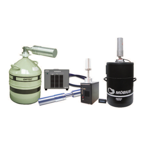
ORTEC Detective X User manual

ORTEC ®
Detective ®X
Portable Radionuclide Identifier
User’s Manual
Software Version 2.3
ORTEC
®
Part No. 1107231 082020
Manual Revision N Printed in USA

ORTEC®Detective®X Handheld Radioisotope Identifier 1107231N / 082020
ii
WARRANTY
ORTEC warrants that the items will be delivered free from defects in material or workmanship. ORTEC makes no other
warranties, express or implied, and specifically NO WARRANTY OF MERCHANTABILITY OR FITNESS FOR A PARTICULAR
PURPOSE.
ORTEC’s exclusive liability is limited to repairing or replacing at ORTEC’s option, items found by ORTEC to be defective
in workmanship or materials within one year from the date of delivery. ORTEC’s liability on any claim of any kind,
including negligence, loss, or damages arising out of, connected with, or from the performance or breach thereof, or
from the manufacture, sale, delivery, resale, repair, or use of any item or services covered by this agreement or purchase
order, shall in no case exceed the price allocable to the item or service furnished or any part thereof that gives rise to
the claim. In the event ORTEC fails to manufacture or deliver items called for in this agreement or purchase order,
ORTEC’s exclusive liability and buyer’s exclusive remedy shall be release of the buyer from the obligation to pay the
purchase price. In no event shall ORTEC be liable for special or consequential damages.
Quality Control
Before being approved for shipment, each ORTEC instrument must pass a stringent set of quality control tests designed
to expose any flaws in materials or workmanship. Permanent records of these tests are maintained for use in warranty
repair and as a source of statistical information for design improvements.
Repair Service
If it becomes necessary to return this instrument for repair, it is essential that Customer Services be contacted in advance
of its return so that a Return Authorization Number can be assigned to the unit. Also, ORTEC must be informed, either
in writing, by telephone [(865) 482-4411], or by facsimile transmission [(865) 483-2133], of the nature of the fault of the
instrument being returned and of the model, serial, and revision (“Rev” on rear panel) numbers. Failure to do so may
cause unnecessary delays in getting the unit repaired. The ORTEC standard procedure requires that instruments
returned for repair pass the same quality control test that are used for new-production instruments. Instruments that
are returned should be packed so that they will withstand normal transit handling and must be shipped PREPAID via Air
Parcel Post or United Parcel Service to the designated ORTEC repair center. The address label and the package should
include the Return Authorization Number assigned. Instruments being returned that are damaged in transit due to
inadequate packaging will be repaired at the sender’s expense, and it will be the sender’s responsibility to make claim
with the shipper. Instruments not in warranty should follow the same procedure and ORTEC will provide a quotation.
Damage in Transit
Shipments should be examined immediately upon receipt for evidence of external or concealed damage. The carrier
making delivery should be notified immediately of any such damage, since the carrier is normally liable for damage in
shipment. Packing materials, waybills, and other such documentation should be preserved in order to establish claims.
After such notification to the carrier, please notify ORTEC of the circumstances so that assistance can be provided in
making damage claims and in providing replacement equipment, if necessary.
Copyright ©2020, Advanced Measurement Technology, Inc. All rights reserved.
ORTEC® is a registered trademark of Advanced Measurement Technology, Inc. All other trademarks used herein are the property of
their respective owners.

1107231N / 082020 ORTEC®Detective®X Handheld Radioisotope Identifier
iii
TABLE OF CONTENTS
Warranty .............................................................................................. ii
Table of Contents ................................................................................ iii
Figures ............................................................................................... vii
Tables .................................................................................................. x
Safety Instructions and Symbols......................................................... xi
1. Getting Started ................................................................................ 1
1.1 The Detective X Transport Case and Contents .......................................... 1
1.2 Detective X Features ............................................................................ 2
1.3 Unpacking .......................................................................................... 4
1.4 Power-Up ........................................................................................... 5
1.5 Turning the Cooler On .......................................................................... 6
1.6 Detective X Accessories ........................................................................ 7
1.6.1 Power Supply.............................................................................. 7
1.6.2 Shoulder Strap............................................................................ 8
1.6.3 Bluetooth Headset ....................................................................... 9
1.6.3.1 Configure a New Bluetooth Headset ................................. 9
1.6.4 USB Cable ................................................................................ 10
1.6.5 USB Flash Drive and MicroSD Card ............................................... 10
1.6.6 Detector Cover, Optional Collimators, Filter, and Neutron Detector .... 10
2. System Overview ........................................................................... 11
2.1 The User Interface ............................................................................. 11
2.2 Gamma-Ray Detectors ....................................................................... 11
2.3 Modular Neutron Detector ................................................................... 12
2.4 Detector Reference Points ................................................................... 12
2.4.1 The Internal Batteries ................................................................ 14
2.4.2 Vehicle Power Adapter Cable ....................................................... 15
2.4.3 External Battery Power Option ..................................................... 15
2.5 Instrument Enclosure ......................................................................... 15
2.6 Collimators (Green and Peach)............................................................. 16
2.7 Low-Energy Filter (Red) ...................................................................... 16
2.8 Operating Cautions and Notes.............................................................. 17
2.9 Preparing the Detective X for Shipping .................................................. 18
2.9.1 Shipping Li-ion Batteries............................................................. 18
2.10 System Software Applications .............................................................. 19
3. Launcher Application ..................................................................... 21
4. Detective X Application.................................................................. 23
4.1 Data Management and Communication.................................................. 23
4.2 User Input ........................................................................................ 23
4.2.1 Moving Back to the Previous Screen ............................................. 24
4.3 Personnel Safety Alerts....................................................................... 24

ORTEC®Detective®X Handheld Radioisotope Identifier 1107231N / 082020
iv
4.4 Detective X Software Overview ............................................................ 24
4.4.1 Adjusting the Audio and Vibratory Alerts ....................................... 30
4.4.2 Data Storage Settings ................................................................ 31
4.4.3 Exiting and Restarting the Detective X Application .......................... 32
4.5 Alarm Conditions ............................................................................... 32
4.5.1 Require Alarms to be Acknowledged?............................................ 32
4.5.2 Personnel Hazard Alarm ............................................................. 33
4.5.3 System Errors........................................................................... 34
4.5.4 Nuclide-Identified Alarm ............................................................. 37
4.6 Detect Mode ..................................................................................... 38
4.6.1 The Signal Index ....................................................................... 39
4.6.2 The SNM Index ......................................................................... 39
4.6.3 Identification (IDs) Box .............................................................. 39
4.6.4 Detect Mode Integration Time ..................................................... 41
4.6.5 Low-Confidence Expert (LCX) Mode .............................................. 42
4.6.5.1 Customizing LCX Mode ................................................ 43
4.7 Identify Mode.................................................................................... 44
4.7.1 Spectrum View.......................................................................... 46
4.7.2 Intense View ............................................................................ 47
4.7.3 Ending the ID Mode Measurement Manually or Automatically............ 48
4.7.3.1 Capturing Optional Metadata ........................................ 48
4.7.4 Multiple ID Measurements in One Data File .................................... 49
4.7.4.1 Setting Up and Performing Multiple Measurements ........... 50
4.8 Manual Data File Transfer.................................................................... 51
4.8.1 Reachback File Access ................................................................ 52
4.8.2 USB Flash Drive File Access......................................................... 52
4.8.3 Mobile Device Center File Access.................................................. 52
4.8.4 WiseMo File Access .................................................................... 54
4.9 Connecting the Detective X to a Network ............................................... 54
4.10 USB Interface for Detective X .............................................................. 57
4.11 Remote Control of Detective X ............................................................. 58
4.12 Reachback Email Setup....................................................................... 61
4.12.1 SMTP Server for Reachback Email.............................................. 62
4.13 Recalling Previously Collected Data Files................................................ 63
4.14 Measuring Ambient Background ........................................................... 64
4.15 System Energy Calibration .................................................................. 66
4.15.1 A Brief Introduction to Gain Stabilization..................................... 66
4.15.2 Calibrating the Detective X ....................................................... 67
4.15.2.1 Using Alternate Calibration Sources ............................... 68
4.15.2.2 Require New Background After Calibration ...................... 68
4.15.2.3 Adding More Calibration Sources ................................... 69
4.16 Modifying Nuclide Threat Status ........................................................... 70
4.17 Password-Protecting the Advanced Settings and ID Mode Spectrum View
...................................................................................................... 71

1107231N / 082020 ORTEC®Detective®X Handheld Radioisotope Identifier
v
4.17.1 Password............................................................................... 71
4.17.2 ID Mode Spectrum .................................................................. 72
4.18 Deploying Multiple Units with Identical Settings ...................................... 72
5. Sleuth Application.......................................................................... 75
5.1 User Input ........................................................................................ 75
5.2 Sleuth Startup and Data File Management ............................................. 75
5.3 Sleuth Home Screen........................................................................... 77
5.3.1 Dead Time Display..................................................................... 77
5.3.2 Missing System Background File .................................................. 77
5.3.3 Distance Optimization ................................................................ 78
5.3.4 Other Icons and Settings ............................................................ 79
5.4 Collecting Data.................................................................................. 80
5.5 Exporting and Deleting Data ................................................................ 81
5.6 Exiting Sleuth ................................................................................... 82
5.7 Sleuth Data Files ............................................................................... 82
6. Mobile MCB Server Application ...................................................... 83
6.1 The CONNECTIONS/MCB Properties Layer.............................................. 83
6.2 Accessing the Detective X via Network .................................................. 84
6.3 Quantitative Spectroscopy with GammaVision ........................................ 84
Mobile Field Kit API ...................................................... 85
A.1 Introduction...................................................................................... 85
A.2 Version ............................................................................................ 85
A.3 Simple Command Testing.................................................................... 85
A.4 Request ........................................................................................... 86
A.5 Response ......................................................................................... 86
A.6 Resources......................................................................................... 86
A.7 System Information ........................................................................... 86
A.8 Status.............................................................................................. 87
A.9 Live Data Access................................................................................ 88
A.9.1 Dose Rate Count Rate ................................................................ 88
A.10Spectrum ......................................................................................... 91
A.11Calibration........................................................................................ 92
A.12N42 Spectrum ................................................................................... 93
A.13Remote Control ............................................................................... 102
A.13.1 Start Spectrum Acquisition ..................................................... 102
A.13.2 Stop Spectrum Acquisition...................................................... 102
A.13.3 Clear Spectrum..................................................................... 102
A.14Workflow........................................................................................ 102
A.14.1 System Initialization.............................................................. 102
A.14.2 Dose and Count Rate Mode..................................................... 102
A.14.3 Start the Detective X ID Mode................................................. 103
Specifications and Care............................................... 105
B.1 Detectors ....................................................................................... 105

ORTEC®Detective®X Handheld Radioisotope Identifier 1107231N / 082020
vi
B.2 Hardware ....................................................................................... 105
B.3 Physical Specifications ...................................................................... 106
B.4 Communication Software .................................................................. 106
B.5 Mobile MCB Server........................................................................... 107
B.6 Cleaning Instructions........................................................................ 107
B.6.1 Cleaning the Exterior ............................................................... 107
B.6.2 Cleaning the Fan Compartment.................................................. 107
B.7 Replacing the Internal Batteries ......................................................... 107
Nuclide ID Table ......................................................... 109
Troubleshooting ......................................................... 115
D.1 Detective X Application Stops ............................................................ 115
D.2 Detective X Was Dropped.................................................................. 115
D.3 Sudden Cooler Failure ...................................................................... 115
D.4 Detective X Will Not Turn On ............................................................. 116
D.5 Forgot the Password......................................................................... 116
D.6 Peak Centroid, FWHM, or Calibration Adjustment Value Has Changed
Dramatically Since the Last Calibration................................................ 116
D.7 GPS Issues ..................................................................................... 117
D.7.1 Delayed Display of Location Coordinates ..................................... 117
D.7.2 “GPS Not Communicating” ........................................................ 117
Calibration Instructions Using Tungsten Welding
Electrodes P/N DETECTIVE-X-ACC-TH-CAL for the Detective-X.... 119
E.1 Adding Th-232 to the Calibration Sources Table .................................... 119
E.2 Calibrating the Detective X Using the Thorium Welding Electrodes (Th-
232) P/N DETECTIVE-X-ACC-TH-CAL................................................... 119

1107231N / 082020 ORTEC®Detective®X Handheld Radioisotope Identifier
vii
FIGURES
Figure 1. Transport Case .................................................................................. 1
Figure 2. Detective X Side View (with Passive Detector Cover Attached)................... 2
Figure 3. Top View .......................................................................................... 2
Figure 4. Rear Panel ........................................................................................3
Figure 5. Rear-Panel Data Connectors (Original Design) ........................................ 3
Figure 6. Rear-Panel Data Connectors (Enhanced Communication Design)................ 3
Figure 7. Adapter Accessories ...........................................................................4
Figure 8. Arrows Show Proper Power Connector Orientation ................................... 4
Figure 9. Power Supply Indicator LED.................................................................5
Figure 10. Power.............................................................................................5
Figure 11. Screen After Initial Power Up..............................................................5
Figure 12. Turn Cooler On ................................................................................6
Figure 13. Status: Cooling ................................................................................ 7
Figure 14. Strap with Retractable Stylus .............................................................8
Figure 15. Strap Quick Disconnect .....................................................................8
Figure 16. Headset with Boom Open .................................................................. 9
Figure 17. Pairing a New Bluetooth Headset with the Detective X ............................9
Figure 18. MicroSD USB Flash Drive Adapter ..................................................... 10
Figure 19. Collimator/Filter/Neutron Detector Connector...................................... 10
Figure 20. Detector Vertical Reference Points..................................................... 13
Figure 21. Detector Horizontal Reference Points ................................................. 13
Figure 22. Charge Status Indicator and Pull Tab ................................................. 14
Figure 23. DC Plug Retention Force Adjustment Slider......................................... 15
Figure 24. Stainless Steel Collimator ................................................................ 16
Figure 25. System Power Down Message .......................................................... 18
Figure 26. Li-ion Battery Shipping Label............................................................ 19
Figure 27. Launcher Screen ............................................................................ 21
Figure 28. (N)avigate and (S)elect Buttons........................................................ 23
Figure 29. Detect Mode – Ready to Select ......................................................... 23
Figure 30. Text Entry Screen........................................................................... 24
Figure 31. Detect Mode Screen........................................................................ 25
Figure 32. ID Mode Screen ............................................................................. 25
Figure 33. Optional Metadata for ID Mode Data.................................................. 26
Figure 34. Basic Software Organization............................................................. 27
Figure 35. Detective X Status Indicators ........................................................... 28
Figure 36. Detect Mode Screen........................................................................ 29
Figure 37. ID Mode Screen ............................................................................. 29
Figure 38. Audio Settings ............................................................................... 31
Figure 39. Data Storage ................................................................................. 31
Figure 40. Setting the Require Acknowledge Flag ............................................... 33

ORTEC®Detective®X Handheld Radioisotope Identifier 1107231N / 082020
viii
Figure 41. Personnel Hazard Alarm .................................................................. 33
Figure 42. Personnel Hazard Alarm Settings ...................................................... 34
Figure 43. Personnel Hazard Full Screen Alarm .................................................. 34
Figure 44. Example of System Error Alarm ........................................................ 35
Figure 45. Over-Range Condition ..................................................................... 36
Figure 46. Over-Range Alarm with Acknowledge Button....................................... 37
Figure 47. Am-241 Unshielded Identification Latched by the Acknowledge Button.... 38
Figure 48. Detect Mode Screen........................................................................ 38
Figure 49. Signal Index Strip Chart History and Current Level .............................. 39
Figure 50. SNM Index Strip Chart History and Current Level................................. 39
Figure 51. IDs Box ........................................................................................ 40
Figure 52. Threat Source Shown in ID List......................................................... 41
Figure 53. Detect Mode Integration Time .......................................................... 42
Figure 54. Suspect Nuclide Identification Alarm in LCX Mode ................................ 43
Figure 55. LCX Mode Enable/Disable Checkbox .................................................. 43
Figure 56. ID Mode Screen ............................................................................. 45
Figure 57. Entire Spectrum Displayed (Showing Marker Position and Channel Content)
.................................................................................................. 46
Figure 58. Expanded Spectrum with Marker Near 1173 keV (with Logarithmic Vertical
Scaling) ....................................................................................... 47
Figure 59. List of the Most Intense Peaks by Decreasing Q Value .......................... 48
Figure 60. Setting the Fixed Count Time in ID Mode............................................ 48
Figure 61. Optional Metadata for ID Mode Data.................................................. 49
Figure 62. Enable Collection of Multiple Spectra in a Single File............................. 50
Figure 63. Set Up Parameters for Multiple Spectrum ID Mode............................... 50
Figure 64. The Unit is Connected to the PC........................................................ 53
Figure 65. Choose the File Management Browse Option ....................................... 53
Figure 66. Rear Panel with USB Dongles Installed............................................... 54
Figure 67. Wired Ethernet Settings Page ........................................................... 55
Figure 68. Typical WiFi Network Selection ......................................................... 56
Figure 69. WiFi Connected .............................................................................. 56
Figure 70. USB Settings Page.......................................................................... 57
Figure 71. Enabling Remote Control Operation ................................................... 58
Figure 72. WiseMo Host Application.................................................................. 58
Figure 73. PC-Based WiseMo Guest Application .................................................. 59
Figure 74. PC-Based Remote Desktop Window with Default Skin ........................... 60
Figure 75. iOS WiseMo Guest App on iPhone Connected to Detective X .................. 60
Figure 76. Reachback Settings ........................................................................ 61
Figure 77. Reachback Email ............................................................................ 62
Figure 78. Remote Control Window .................................................................. 63
Figure 79. WiseMo File Manager ...................................................................... 63
Figure 80. Recall Screen................................................................................. 64

1107231N / 082020 ORTEC®Detective®X Handheld Radioisotope Identifier
ix
Figure 81. Recall Details Screen ...................................................................... 64
Figure 82. Background Collection for Use in Analysis........................................... 65
Figure 83. Background Settings....................................................................... 66
Figure 84. Neutron Background Changed .......................................................... 66
Figure 85. Current Gain Stabilizer Adjustment ................................................... 67
Figure 86. Calibrate Screen............................................................................. 68
Figure 87. Calibration Settings Screen .............................................................. 69
Figure 88. Define Calibration Sources ............................................................... 69
Figure 89. Default Identification Table Listing .................................................... 70
Figure 90. Preparing to Change Default Innocent Nuclide to Threat Status.............. 71
Figure 91. Default Innocent Nuclide Changed to Threat Status (and Marked with
Asterisk) ...................................................................................... 71
Figure 92. Password Setup Screen ................................................................... 72
Figure 93. Confirmation of Saved Settings......................................................... 72
Figure 94. Partial Contents of Typical Settings.txt File ......................................... 73
Figure 95. Starting Sleuth from the Launcher Interface ....................................... 76
Figure 96. Delete Sleuth Data Message............................................................. 76
Figure 97. Clear Internal Memory Confirmation .................................................. 76
Figure 98. Sleuth Home Screen ....................................................................... 77
Figure 99. Sleuth Dead Time Display ................................................................ 77
Figure 100. Missing System Background Icon .................................................... 77
Figure 101. Move Closer................................................................................. 78
Figure 102. Distance OK................................................................................. 78
Figure 103. Move Back................................................................................... 78
Figure 104. Distance Entered .......................................................................... 78
Figure 105. Pause ......................................................................................... 80
Figure 106. Measurement Complete ................................................................. 81
Figure 107. Export in Progress ........................................................................ 81
Figure 108. Home Button ............................................................................... 82
Figure 109. Mobile MCB Server UI from the Launcher Application.......................... 83
Figure 110. Example Instrument Status via Internet Browser Interface .................. 85
Figure 111. Example Start Acquisition via Internet Browser Interface .................... 86
Figure 112. Reset Cooler Error ...................................................................... 116

ORTEC®Detective®X Handheld Radioisotope Identifier 1107231N / 082020
x
TABLES
Table 1. Battery Specifications (Subject to Change) ............................................ 19
Table 2. Threat Energies ................................................................................ 44
Table 3. Advanced Setting Options................................................................... 80
Table 4. System Information........................................................................... 87
Table 5. Status Information ............................................................................ 88
Table 6. Live Data Access Information .............................................................. 90
Table 7. Spectrum Information........................................................................ 92
Table 8. Calibration Information ...................................................................... 93
Table 9. Nuclide ID Table ............................................................................. 109

1107231N / 082020 ORTEC®Detective®X Handheld Radioisotope Identifier
xi
SAFETY INSTRUCTIONS AND SYMBOLS
This manual contains up to three levels of safety instructions that must be observed in order to avoid personal
injury and/or damage to equipment or other property. These are:
DANGER Indicates a hazard that could result in death or serious bodily harm if the safety instruction
is not observed.
WARNING Indicates a hazard that could result in bodily harm if the safety instruction is not observed.
CAUTION Indicates a hazard that could result in property damage if the safety instruction is not
observed.
Please read all safety instructions carefully and make sure they are understood fully before attempting to use
this product.
In addition, the following symbol might appear on the product:
ATTENTION – Consult the manual in all cases where this symbol is marked in order
to determine the nature of the potential hazards and any actions that must be taken
to avoid them.
DANGER – Hazardous voltage
Protective earth (ground) terminal
Please read all safety instructions carefully and make sure they are understood fully before attempting to use
this product.

ORTEC®Detective®X Handheld Radioisotope Identifier 1107231N / 082020
xii
THIS PAGE INTENTIONALLY LEFT BLANK.

1
1. GETTING STARTED
Congratulations on purchasing the ORTEC® Detective® X Handheld Radionuclide Identifier. The
Detective X is unparalleled in the detection and identification of threat and innocent radionuclides, even in
shielded and masked configurations. Although it is a precision scientific instrument, the Detective X is
designed for continuous, hard use in the heaviest weather, seas, air, and terrain. It delivers rapid, accurate
screening of vehicles, containers, vessels, buildings, rooms, objects, people, and areas, providing an “expert
in a box” for radionuclide identification. Operators can detect radiation, verify radiation alarms, localize the
source, identify the radioactive material (even measuring it together with blank and unknown samples for
additional rigor and quality assurance), and assess the threat status of the detected material. The
straightforward Send to Reachback function can provide a link to technical experts for assessment and
adjudication assistance.
This chapter introduces the main features of the Detective X, then walks through the procedure for powering
it up and cooling it to operating temperature. More detailed information begins in Chapter 2.
1.1 THE DETECTIVE X TRANSPORT CASE AND CONTENTS
The Detective X is shipped in a rugged, foam-lined transport case suitable for shipment via common carrier
or as checked baggage on commercial passenger aircraft. Figure 1 shows the loaded Detective X transport
case as delivered from the factory.
Figure 1. Transport Case
(Figure 1 shows the optional neutron detector already attached to the front of the unit. If the neutron
detector was not purchased, the unit ships with the detector cover attached, and the cavity for the detector
cover is empty.) The case includes an inset for a pair of extra batteries (purchased separately from ORTEC).
Note that the instrument is shipped with the COOLER OFF to prevent damage from overheating. NEVER
operate the cooler when the unit is enclosed in the transport case or wrapped in other insulating material.

ORTEC®Detective®X Handheld Radioisotope Identifier 1107231N / 082020
2
1.2 DETECTIVE X FEATURES
Figure 2 through Figure 6 show the major features of the Detective X. Features and operating details are
discussed in detail in Chapters 3, 4, 5, and 6.
Figure 2. Detective X Side View (with Passive Detector Cover Attached)
Figure 3. Top View

1107231N / 082020 1. GETTING STARTED
3
Figure 4. Rear Panel
Figure 5. Rear-Panel Data Connectors (Original Design)
Figure 6. Rear-Panel Data Connectors (Enhanced Communication Design)
(ORTEC
use only)
(ORTEC
use only)
Ethernet
connector
USB flash
drive only
WiFi connection
dongle only
USB-to-PC
connector

ORTEC®Detective®X Handheld Radioisotope Identifier 1107231N / 082020
4
1.3 UNPACKING
1. Remove the Detective X, the power adapter with DC cable, and the mains adapter package from the case.
Figure 7. Adapter Accessories
2. Referring to Figure 8, on the upper-left of the rear panel, unscrew the protective cover from the DC power
connector and plug in the DC power cable from the power supply. The connector is keyed, so use the
arrows to line it up correctly, then push in and twist the ring clockwise to lock the connector in place. Do
not force or overtighten the connection.
Figure 8. Arrows Show Proper Power Connector Orientation

1107231N / 082020 1. GETTING STARTED
5
3. Find the mains power cord and the appropriate wall plug adapter for the operating location. Press the
wall plug adapter onto the power cord and connect the power cord into the power supply. Finally, plug
the cord into the wall outlet. The power supply is operating when the indicator LED on the power supply
is lit (Figure 9). Note that the internal batteries charge any time the unit is connected to external power,
whether or not the touchscreen computer/detector power button is on or off.
Figure 9. Power Supply Indicator LED
1.4 POWER-UP
Referring to Figure 3 and Figure 10, the middle button on the top of the Detective X is the
power button. To power up, press and hold the button for at least 5 seconds. The
touchscreen will illuminate, and the unit will begin its boot-up sequence, which takes just a
few seconds. (Note that the unit can also be turned off by pressing and holding the power
button for about 5 seconds; this interval prevents unintentional power-off.)
When boot-up is complete, the Detect Mode home screen will be displayed, as shown in Figure 11. Note the
Status: NOT Ready indicator, and the red error message, The Cooler is turned off! The next step will be to
turn on the cryogenic cooler.
Figure 11. Screen After Initial Power Up
Figure 10.
Power

ORTEC®Detective®X Handheld Radioisotope Identifier 1107231N / 082020
6
1.5 TURNING THE COOLER ON
1. In the lower right corner, tap the Settings button to open the Settings page (Figure 12). Then tap Turn
Cooler ON. Note that this is an on/off toggle, and the button label changes with the cooler state.
2. At this point, the “The Cooler is turned off!”error message will no longer be displayed, and the
instrument status will say Status: Cooling Phase 1 ( Figure 13).
3. The instrument may be temporarily disconnected from external power and moved to a different location
if desired.
4. Cooling will continue through four phases before the status message changes to Status: READY.
There is no need to continue displaying the Settings page during cooldown, although the user may wish to
tap the Status button to display system temperatures and track cooldown progress.
Figure 12. Turn Cooler On
NOTE
The default factory settings will be enabled to automaticall
y start the ‘traditional’ Detective
X user interface upon system power up. This behavior can be modified to start other
onboard applications (i.e., Sleuth, Mobile MCB Server, or Launcher). If the instrument
settings have been modified to start an alternate program, please refer to Chapters 3
(Launcher), 5 (Sleuth), and 6 (Mobile MCB Server).
NOTE
Once turned on, the cooler stays on, even if the Power button is turned off. To completely
shut down the instrument, press the power button on the front of the instrument. A
message will be displayed asking to turn off the cooler. See Section 2.9 for more
information.

1107231N / 082020 1. GETTING STARTED
7
Figure 13. Status: Cooling
Cooldown from room temperature typically takes less than 8 hours. This is a good time to become familiar
with the Detective X’s features and operating instructions. Be sure to see the operating cautions and notes
in Section 2.8.
1.6 DETECTIVE X ACCESSORIES
The following standard accessories are supplied with the Detective X and are included in the shipping
container (refer to Figure 1):
User’s manual
Universal power supply with captive DC cable
AC mains cord with male adapters for any mains power source
Heavy duty shoulder strap with retractable stylus
Bluetooth® headset and charger
12-V automobile power adapter
USB cable (USB A to USB mini B, 3 m)
Detector cover (see text)
1.6.1 Power Supply
The power supply is rated at 100–240 VAC and 50/60 Hz. The DC cable to the Detective X is captive, and the
mains socket is IEC 320 C14 compatible.

ORTEC®Detective®X Handheld Radioisotope Identifier 1107231N / 082020
8
1.6.2 Shoulder Strap
The shoulder strap (Figure 14) is connected by quick-release fasteners that clip
to diagonal corners of the Detective X (see Figure 15). (Figure 2 shows the
attachment points on the right side of the housing; there are two on the left
side, as well.) The two strap orientations give both right- and left-handed users
a clear view of the display. The strap includes a stylus attached by a retractable
polyaramid cord. The stylus is especially useful for operating the touchscreen if
the operator is wearing protective gloves, and for entering alphanumeric
information. When not in use, the stylus is held against the strap with an
embedded magnet. (Note that the stylus ships from the factory with a
protective rubber boot over the end [red circle in Figure 14] that may be
discarded.)
Figure 15. Strap Quick Disconnect
Figure 14. Strap with
Retractable
Stylus
Table of contents
Other ORTEC Security Sensor manuals
Popular Security Sensor manuals by other brands

Niko
Niko KNX SG360P instruction manual
RKI Instruments
RKI Instruments 35-3001-06H-DIL Operator's manual
Genesis
Genesis LG2 WP-3020 Installation handbook

Powerfix Profi
Powerfix Profi 107555 operating instructions
BUCKINGHAM MFG
BUCKINGHAM MFG 488 Series Instructions & warnings
Ezviz
Ezviz T2 quick start guide
Inficon
Inficon Contura S600 Translation of the original operating instructions

Sperian
Sperian MILLER 1006320 L General Instructions for Use
MDT Technologies
MDT Technologies SCN-P360D3.01 Technical manual

Damar
Damar D450 Installation and operating instructions
Visonic
Visonic NEXT K9-85 installation instructions
Baumer
Baumer FVDK 10N66Y0 quick start guide
