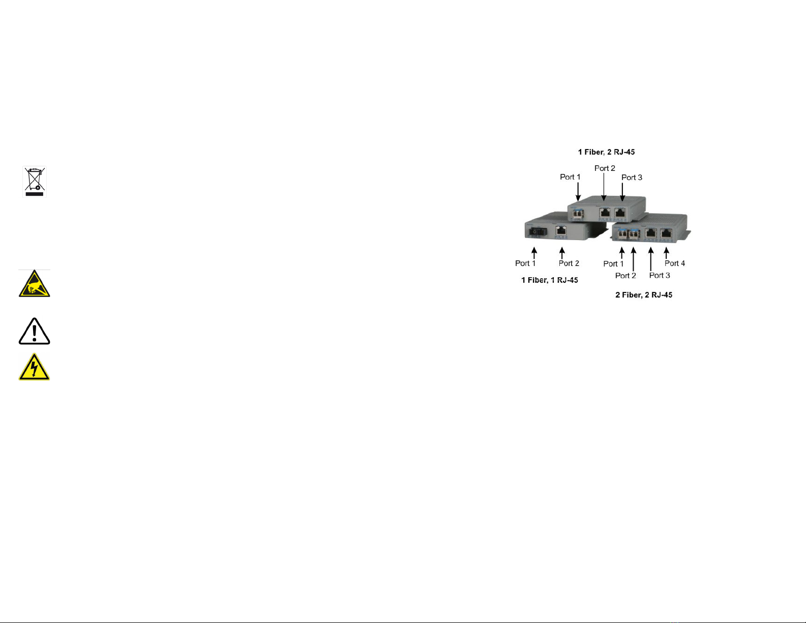
RJ-45 Port 2 does not cause the loss of link to propagate. The loss only propagates
in the Port 1 to Port 2 direction. See Port Congurations on Page 4.
Note: A loss of link or loss of signal is when the optical receiver on the media converter
can no longer detect the presence of an optic signal.
Note: On models with 2 ber ports or 2 RJ-45 ports, both ports of the same media type
must be in link fault condition before the fault will propagate.
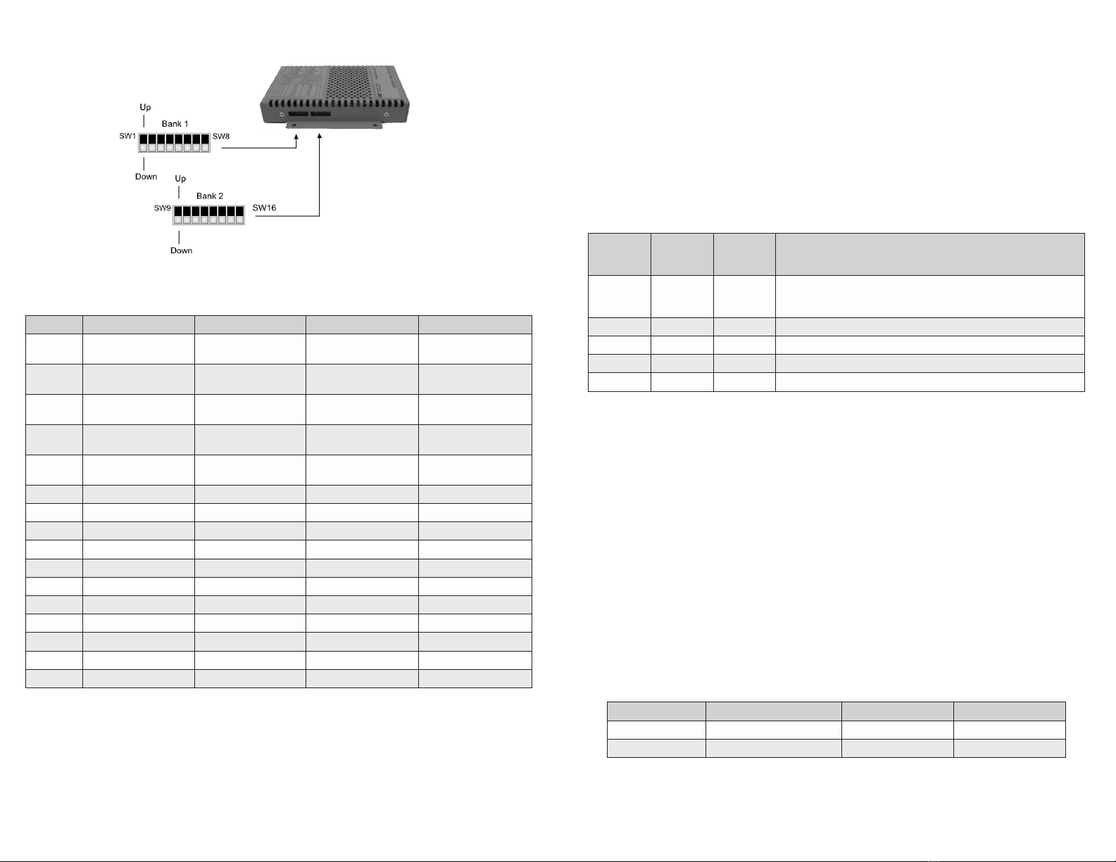
SW12 SW13 Function
DOWN DOWN Link Segment (LS)
UP DOWN
Asymmetrical Link Propagate Port 1 to Port 2 (1+1 - 2 Port models),
Port 1 to Port 2 and Port 3 (1+2 - 3 Port models),
Port 1 and Port 2 to Port 3 (2+1 - 3 Port models) and
Port 1 and Port 2 to Port 3 and Port 4 (2+2 - 4 Port models).
DOWN UP
Asymmetrical Link Propagate Port 2 to Port 1 (1+1 - 2 Port models),
Port 2 and Port 3 to Port 1 (1+2 - 3 Port models)
Port 3 to Port 1 and Port 2 (2+1 - 3 Port models)
and Port 3 and Port 4 to Port 1 and Port 2 (2+2 - 4 Port models)
UP UP Invalid Conguration
Link Modes
SW14 - Power Sourcing Reset
The OmniConverter can be congured to disable (reset) the PoE output power for 2
seconds after a loss of receive link on any ber port. This feature is typically used
to allow a PD to re-initialize after a failure on the incoming ber. When this DIP-
switch is in the Up “Lk Loss” position, the module will disable PoE output power for
2 seconds following a loss of receive link on any ber port. When this DIP-switch
is in the Down position, PoE output power does not reset on ber link loss.
SW15 and SW16 - Port Redundant Mode
SW15 and SW16 are valid on models with 2 ber ports only. Port redundancy is
available when connected to Omnitron and third party devices with 2 ber ports.
SW15 controls the port redundancy mode of the module. When SW15 is in the Down
“Off” (default) position, the ber ports operate in a non-redundant (independent)
mode. When SW15 is in the Up “On” position, the ber ports operate as redundant
links. A fault on the primary ber port (Port 1), will cause a fail over to the secondary
ber port (Port 2) within 50msec.
SW16 enables the module to return to the primary ber port (Port 1) after the ber
link has been restored for 6 seconds. When SW16 is in the Down “Off” position,
return to primary is disabled (inactive). When the SW16 is in the Up “On” position,
return to primary is enabled.
Page 9
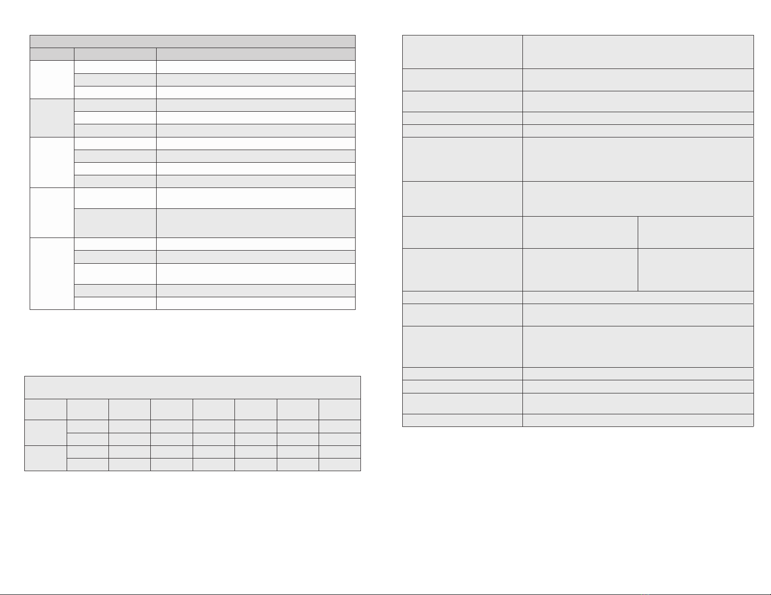
Switch 15
P1+P2 Redun
Switch 16
Rtn P1 Function
DOWN (Off) DOWN (Off) Non-redundant mode - normal mode
DOWN (Off) UP (On) Non-redundant mode - normal mode
UP (On) DOWN (Off) Redundant mode - no return to primary
UP (On) UP (On) Redundant mode - return to primary
Port Redundancy Modes
2) Installing the Module
Wall Mounting
The wall mounting height of the module should be less than or equal to 2 meters
(6.6 feet) from the oor. Use the four mounting holes on the module to secure the
module to the wall. The module can accommodate #6 screws (not included).
Installation of the module should be such that the air ow in the front, back, side
and top vents of the switch are not compromised or restricted.
The accessory cables should have their own strain relief and do not pull down on
the module.
Rack Mounting
The module can be rack mounted using the optional Rack Mount Shelf (8260-0).
Refer to the Rack Mount Shelf user manual (040-08260-001x) for the proper
installation guidelines.
Follow the same guidelines above when rack mounting the module.
DIN-rail Mounting
The module can be DIN-rail mounted using the optional DIN-rail Mounting Bracket
(8250-0) or the optional DIN-rail Mounting Clip (8251-0). Refer to the user manuals
(040-08250-001x or 040-08251-001x) for the proper installation guidelines.
3) Apply Power
AC Power
Secure the ground wire to the NEBS grounding screw located on the back of the
module.
To power the unit using the AC/DC adapter, route the power cord through the
provided strain relief for additional support. Then connect the barrel connector
at the end of the wire on the AC/DC adapter to the 2.1mm DC barrel connector
(center-positive) on the unit. Connect the AC/DC adapter to the AC outlet. Conrm
that the module has powered up properly by checking the Power LED located on
the front of the installed module.
Installation of the equipment should be such that the air ow in the front, back, side
and top vents of the chassis are not compromised or restricted.
Page 10