manuals.online logo
Brands
  1. Home
  2. •
  3. Brands
  4. •
  5. OST
  6. •
  7. Media Converter
  8. •
  9. OST iConverter 10GXT User manual

OST iConverter 10GXT User manual

iConverter®10GXT
Standalone Module User Manual
Product Overview
The iConverter 10GXT is a 10/100/1000BASE-T copper to 1000BASE-X or 10GBASE-R ber
media converter, and is available as a compact, unmanaged standalone unit. The iConverter
10GXT supports jumbo frames up to 10,056 bytes. The 10GXT models are available with
SFP+ or XFP transceivers.
Installation Procedure
1) Congure DIP-switches
2) Install Standalone Module and Connect Cables
3) Verify Operation
1) CONFIGURE DIP-SWITCHES
DIP-SWITCH BANK 1
The location of the DIP-switches is shown in Figure 1.
The function of DIP-switch Bank is outlined in Figure 2.
Switch Legend Function DOWN (Default) UP
SW1 P1 AN/MAN Port 1 Speed and Duplex Auto Manual
SW2
SW3 10G/1000 Port 2 Speed 10G 1000
SW4 P2 AN/MAN Port 2 Negotiation
(1G Mode Only) Auto Manual
SW5
Link Modes
Asymmetrical Link Propagate
Port 1 to Port 2 Link Segment Link Propagate
Port 1 to Port 2
SW6 Asymmetrical Link Propagate
Port 2 to Port 1 Link Segment Link Propagate
Port 2 to Port 1
Figure 2: DIP-switch Denitions
3) VERIFY OPERATION
Once the module has been installed and congured per steps 1 and 2, verify the module is
operational by viewing the LED indicators.
LED Function
“Legend” Color OFF State ON/Blinking State
Power
“PWR” Green No power Solid Green: Module has power
P1 Negotiation Mode
“AN” Green Port is congured for Manual
operation
Solid Green: Port is congured for auto-
negotiation
Blinking Green: Port is congured for
auto-negotiation but has not completed
the process with attached link partner
P1 Link Activity
“100” Green Port not linked at 100M Solid Green: Port linked at 100M
Blinking Green: Data activity
P1 Link Activity
“1000” Green Port not linked at 1000M Solid Green: Port linked at 1000M
Blinking Green: Data activity
P1 Link Activity
“100” and “1000” Green Port not linked at 10M Solid Green: Port linked at 10M
Blinking Green: Data activity
P1 Duplex
“FDX” Green
Port is congured for half
duplex per DIP-switch or
resolved by auto-negotiation
Solid Green: Port is congured for
full duplex operation per DIP-switch or
resolved by auto-negotiation
P2 Speed
“P2 1000”
(SFP+ Model Only)
Green/
Amber Port not linked at 1000M
Solid Green: Port linked at 1000M
Blinking Green: Data activity
Blinking Amber: Port is operating at
1000M and receiving a remote fault
P2 Speed
“10G” Green Port not linked at 10G Solid Green: Port linked at 10G
Blinking Green: Data activity
P2 FDX Green
Port is has negotiated to
half duplex or port has not
established a link
Solid Green: Port is negotiated to full
duplex operation by auto-negotiation
P2 DDMI
“Stats”
Green/
Amber
Transceiver does not support
digital diagnostic or no
transceiver is installed
Green Solid: Transceiver supports
digital diagnostic and no DDMI alarm
detected
Amber Solid: Transceiver supports
digital diagnostic and DDMI alarm
detected
Figure 5: LED Indicators
LED Legend/State Link Speed
“1000” “100”
OFF OFF Port not linked
OFF ON Port linked at 100Mbps
ON OFF Port linked at 1000Mbps
ON ON Port linked at 10Mbps
Figure 6: Port 1 Speed LED Indicators
040-08580-001A 1/16
Page 1
Omnitron Systems Technology * 38 Tesla, * Irvine, CA 92618
949.250.6510 tel * 949.250.6514 fax * www.omnitron-systems.com
©2016 Omnitron Systems Technology, Inc. iConverter is a registered trademark of Omnitron Systems Technology, Inc.
Trademarks are owned by their respective companies. Specications subject to change without notice. All rights reserved.
SW1 and SW2: Port 1 Speed and Duplex
Negotiation mode, duplex mode and speed per Figure 3.
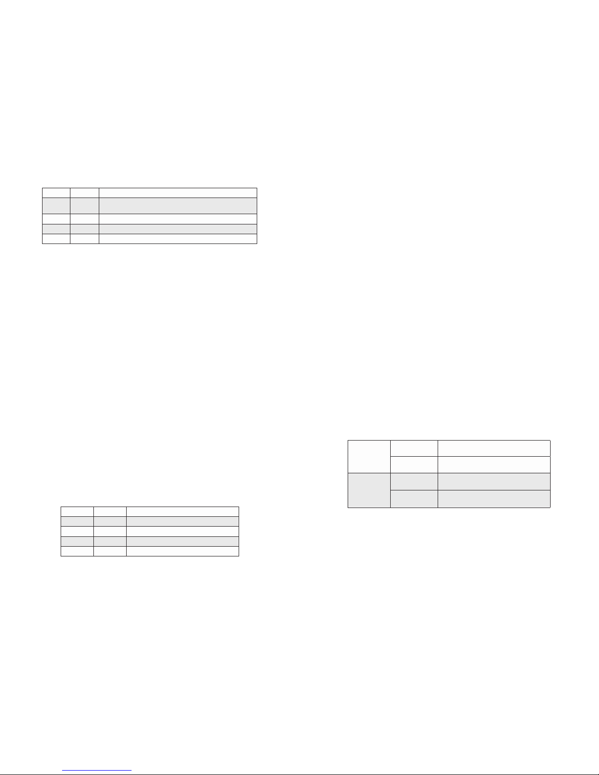
SW1 SW2 RJ-45 Mode of Operation
DOWN DOWN Set to auto-negotiation with the following modes are advertised:
1000FDX, 1000HDX, 100FDX, 100HDX, 10FDX, 10HDX
DOWN UP The RJ-45 port is set to manual and is forced to 10FDX
UP DOWN The RJ-45 port is set to manual and is forced to 100HDX
UP UP The RJ-45 port is set to manual and is forced to 100FDX
Figure 3: Port Speed and Duplex Selection
SW3: Port 2 Speed (SFP+ Model Only)
This DIP-switch congures the speed of the transceiver installed in Port 2. If the DIP-switch is
in the Down “10G” (default) position, the port forces the speed of the transceiver to 10G. If the
DIP-switch is in the Up “1000” position, the port forces the speed of the transceiver to 1000.
SW4: Port 2 Negotiation Mode “AN/MAN” (SFP+ Model Only)
SW4 is used when SW3 is in the Up “1000” position.
When this DIP-switch is in the Down “AN” position (factory default), the ber optic port
automatically determines the duplex and pause modes of the connecting ber optic device.
If the connecting ber optic device cannot provide the proper signal to indicate its own mode
of operation, the DIP-switch should be set to the Up “MAN” position. When Port 2 is set to
manual mode, no capabilities are advertised.
SW5 and SW6: Link Modes
These DIP-switches congure the link mode settings. It is recommended to have link modes
Down position (default) during the initial installation. After the circuit has been tested and
operational, congure the module for the desired mode.
Link Segment
In Link Segment mode, all ports operate independently. A loss of a receive link signal will
only affect the port detecting the loss of signal. All the other ports will continue to generate
a link signal.
Asymmetrical Link Propagate
In Asymmetrical Link Propagate mode, faults are propagated based on the port notation. Port 1
to Port 2 notation indicates the direction the loss of link signal will propagate. A loss of receive
link on the ber optic Port 1 causes the UTP Port 2 to drop its link due to the propagated
state (Port 1 to Port 2). The loss of link on the UTP Port 2 does not cause the loss of link to
propagate. The loss only propagates in the Port 1 to Port 2 direction.
Symmetrical Link Propagate
In Symmetrical Link Propagate mode, the loss of a receive link signal will continue to propagate
through to the next port in the network causing the port to drop link.
SW5 SW6 Function
DOWN DOWN Link Segment (default)
UP DOWN Asymmetrical Link Propagate P1 to P2
DOWN UP Asymmetrical Link Propagate P2 to P1
UP UP Symmetrical Link Propagate
Figure 4: DIP-switch BANK 1 Denitions
Page 2 Page 3
For detailed information on the operation of the different Link Modes, download the application
note “iConverter Link Modes” available on Omnitron’s website:
https://www.omnitron-systems.com/cat_view/20-omnitron-download-center/21-iconverter-
product-documentation/114-application-notes-and-other-documents.php
2) INSTALL STANDALONE MODULE AND CONNECT CABLES
a. The 10GXT is available as a standalone module with or without integrated mounting
brackets. For wall-mounting, use the integrated mounting brackets to attach the 10GXT
to a wall, backboard or other at surface. For tabletop installations, place the unit on a
at level surface. Attach the rubber feet to the bottom of the 10GXT to prevent the unit
from sliding. Make sure the unit is placed in a safe, dry and secure location. Wall-mount
brackets (8249-0) are available to mount the standalone module without integrated
mounting brackets.
To power the unit using the AC/DC adapter, connect the AC/DC adapter to an AC outlet.
Then connect the barrel plug at the end of the wire on the AC/DC adapter to the 2.5mm
DC barrel connector (center-positive) on the unit. Conrm that the unit has powered up
properly by checking the power status LED located on the front of the unit.
To power the unit using a DC power source, prepare a power cable using a two conductor
insulated wire (not supplied) with a 14 AWG gauge minimum. Cut the power cable to the
length required. Strip approximately 3/8 of an inch of insulation from the power cable
wires. Connect the power cables to the unit by fastening the stripped ends to the DC
power connector.
Connect the power wires to the DC power source. The Power LED should indicate the
presence of power.
WARNING: Note the wire colors used in making the positive and negative connections.
Use the same color assignment for the connection at the DC power source.
A ‘P’ clamp is included to provide strain relief for the AC/DC cable. Attach the ‘P’ clamp
to the safety ground screw located at the rear of the module.
NOTE: When using the ‘P’ clamp, attach the ‘P’ clamp to the safety ground screw.
Make sure the ‘P’ clamp in installed between the washer and the screw.
NOTE: A safety ground attachment is provided on the rear of the chassis. Use
the provided ground screw to attach a safety ground.
AC Power
Requirements
AC Adapter:
(US)
100 - 120VAC/60Hz
0.25A @ 120VAC (max)
AC Adapter:
(Universal)
100 - 240VAC/50 - 60Hz
0.25A @ 120VAC (max)
DC Power
Requirements
DC Input:
(Terminal Block)
9 - 16VDC, 2.8A max
2-Pin Terminal (non-isolated)
DC Input:
(AC Adapter)
9 - 16VDC, 2.8A max
2.5mm Barrel Connector
b. Insert the appropriate 10G SFP+, 1G SFP or XFP transceiver (depending on the model
of the module) into Port 2 receptacle on the 10GXT. The release latch of the transceiver
must be in the closed position before insertion.
c. Connect an appropriate multimode or single-mode ber cable to the ber transceiver port
on the 10GXT. It is important to ensure that the transmit (Tx) is attached to the receive
side of the device at the other end and the receive (Rx) is attached to the transmit side.
d. Connect the RJ-45 port via a CAT 6A or better cable to a 10BASE-T, 100BASE-TX or
1000BASE-T Ethernet device.

Other OST Media Converter manuals

OST iConverter XG+ User manual

OST

OST iConverter XG+ User manual

OST iConverter 10/100M User manual

OST

OST iConverter 10/100M User manual

OST iConverter GX/TM2 User manual

OST

OST iConverter GX/TM2 User manual

OST iConverter 2GXT User manual

OST

OST iConverter 2GXT User manual

OST iConverter XG Supplement

OST

OST iConverter XG Supplement

OST iConverter T3 User manual

OST

OST iConverter T3 User manual

OST iConverter CWDM/X User manual

OST

OST iConverter CWDM/X User manual

OST OmniConverter GHPoE/S User manual

OST

OST OmniConverter GHPoE/S User manual

OST OmniConverter GPoE/S User manual

OST

OST OmniConverter GPoE/S User manual

OST iConverter User manual

OST

OST iConverter User manual

Popular Media Converter manuals by other brands

EtherWAN EL2242 quick start guide

EtherWAN

EtherWAN EL2242 quick start guide

Baudcom BD-3224V user manual

Baudcom

Baudcom BD-3224V user manual

CEL-MAR ADA-4021 user manual

CEL-MAR

CEL-MAR ADA-4021 user manual

Pinnacle Systems Dazzle Digital Video Creator 90 quick start guide

Pinnacle Systems

Pinnacle Systems Dazzle Digital Video Creator 90 quick start guide

Belle BGF 24 Operator's manual

Belle

Belle BGF 24 Operator's manual

Yamaha YMC10 owner's manual

Yamaha

Yamaha YMC10 owner's manual

Kramer VM-2DH user manual

Kramer

Kramer VM-2DH user manual

Miteq 9400 Series manual

Miteq

Miteq 9400 Series manual

GSS HDMT 1000 SPTS Assembly instruction

GSS

GSS HDMT 1000 SPTS Assembly instruction

Korenix JetCon 1100 Series user manual

Korenix

Korenix JetCon 1100 Series user manual

Siemens SINAMICS S150 operating instructions

Siemens

Siemens SINAMICS S150 operating instructions

Q-Sonic PE-6084-919 manual

Q-Sonic

Q-Sonic PE-6084-919 manual

ADF Web HD67B18-B2 user manual

ADF Web

ADF Web HD67B18-B2 user manual

Digitrax DS44 installation instructions

Digitrax

Digitrax DS44 installation instructions

Speaka Professional 1229080 operating instructions

Speaka Professional

Speaka Professional 1229080 operating instructions

Aetina MSB-DP24H user manual

Aetina

Aetina MSB-DP24H user manual

RKC INSTRUMENT COM-JH instruction manual

RKC INSTRUMENT

RKC INSTRUMENT COM-JH instruction manual

LDT LS-DEC-NS-F Operating	 instruction

LDT

LDT LS-DEC-NS-F Operating instruction

manuals.online logo
manuals.online logoBrands
  • About & Mission
  • Contact us
  • Privacy Policy
  • Terms and Conditions

Copyright 2025 Manuals.Online. All Rights Reserved.