Kramer DSP-62-AEC User manual

Kramer Electronics Ltd.
DSP-62-AEC –Contents
i
Contents
Introduction 1
Getting Started 1
Overview 2
Typical Applications 3
Defining DSP-62-AEC Digital Sound Processor 4
Mounting DSP-62-AEC 6
Connecting DSP-62-AEC 7
Connecting the Output to a Balanced/Unbalanced Stereo Audio Acceptor 8
Connecting to DSP-62-AEC via RS-232 8
Operating and Controlling DSP-62-AEC 9
Using the Front Panel 9
Operating via Ethernet 9
Using Embedded Webpages 12
Browsing the DSP-62-AEC Webpages 12
Using the Top Status Bar 13
Viewing the Matrix Area 15
Processing Audio Signals 16
Linking Analog Inputs and Outputs 16
Processing a Signal 16
Routing Inputs to Outputs 31
Mixing Audio Signals 35
Audio and Video Settings 39
Defining Audio Settings 39
Defining Video Settings 40
Defining General Settings 41
Performing Firmware Upgrade 42
Importing/Exporting Global Settings 43
Restarting and Resetting the Device 44
Defining Communication Settings 45
Setting Access Security 47
Viewing Device Information 50
Upgrading Firmware 51
Technical Specifications 52
Default Communication Parameters 53
Default EDID 53
Protocol 3000 56
Understanding Protocol 3000 56
Protocol 3000 Commands 57
Result and Error Codes 80

Kramer Electronics Ltd.
DSP-62-AEC –Introduction
1
Introduction
Welcome to Kramer Electronics! Since 1981, Kramer Electronics has been providing a world
of unique, creative, and affordable solutions to the vast range of problems that confront the
video, audio, presentation, and broadcasting professional on a daily basis. In recent years, we
have redesigned and upgraded most of our line, making the best even better!
Getting Started
We recommend that you:
•Unpack the equipment carefully and save the original box and packaging materials for
possible future shipment.
•Review the contents of this user manual.
Go to www.kramerav.com/downloads/DSP-62-AEC to check for up-to-date user manuals,
application programs, and to check if firmware upgrades are available (where appropriate).
Achieving Best Performance
•Use only good quality connection cables (we recommend Kramer high-performance,
high-resolution cables) to avoid interference, deterioration in signal quality due to poor
matching, and elevated noise levels (often associated with low quality cables).
•Do not secure the cables in tight bundles or roll the slack into tight coils.
•Avoid interference from neighboring electrical appliances that may adversely influence
signal quality.
•Position your Kramer DSP-62-AEC away from moisture, excessive sunlight and dust.
Safety Instructions
Caution:
•This equipment is to be used only inside a building. It may only be connected to other
equipment that is installed inside a building.
•For products with relay terminals and GPI\O ports, please refer to the permitted rating
for an external connection, located next to the terminal or in the User Manual.
•There are no operator serviceable parts inside the unit.
Warning:
•Use only the power cord that is supplied with the unit.
•Disconnect the power and unplug the unit from the wall before installing.
•Do not open the unit. High voltages can cause electrical shock! Servicing by qualified
personnel only.
•To ensure continuous risk protection, replace fuses only according to the rating
specified on the product label which is located on the bottom of the unit.

Kramer Electronics Ltd.
DSP-62-AEC –Introduction
2
Recycling Kramer Products
The Waste Electrical and Electronic Equipment (WEEE) Directive 2002/96/EC aims to reduce
the amount of WEEE sent for disposal to landfill or incineration by requiring it to be collected
and recycled. To comply with the WEEE Directive, Kramer Electronics has made
arrangements with the European Advanced Recycling Network (EARN) and will cover any
costs of treatment, recycling and recovery of waste Kramer Electronics branded equipment on
arrival at the EARN facility. For details of Kramer’s recycling arrangements in your particular
country go to our recycling pages at www.kramerav.com/support/recycling.
Overview
Congratulations on purchasing your Kramer DSP-62-AEC Digital Sound Processor.
DSP-62-AEC is a member of the Kramer XSPerience family of DSP products. DSP-62-AEC is
an advanced, professional 6 x 2 audio matrix switcher that includes multi-channel DSP, AEC
(Acoustic Echo Cancellation), HDMI de-embedding, and class compliant USB audio interface.
The comprehensive and user-friendly graphic interface makes configuring every detail of your
audio system intuitive and easy.
DSP-62-AEC provides exceptional quality, advanced and user-friendly operation, and flexible
connectivity.
Exceptional Quality
•Advanced Audio Matrix Switcher –Professional, studio grade signal conversion
technology.
•Teleconference Optimized –Features AEC (Acoustic Echo Cancellation), that prevents
the microphone from picking up the far-end echoed speech, so you only share the audio
spoken directly into the microphone.
•Max. Video Resolution –4K@60Hz (4:4:4).
•Audio De-embedding –De-embeds the audio signal from the HDMI input for routing to
any of the outputs.
•Programmable –Supports up to 10 global presets, 10 mixer snapshot presets and 10
mixer presets per system preset.
•HDMI Support –HDR, CEC, ARC, 4K@60Hz, 3D, Deep Color, x.v.Color™, 7.1 PCM,
Dolby TrueHD, DTS–HD.
Advanced and User-friendly Operation
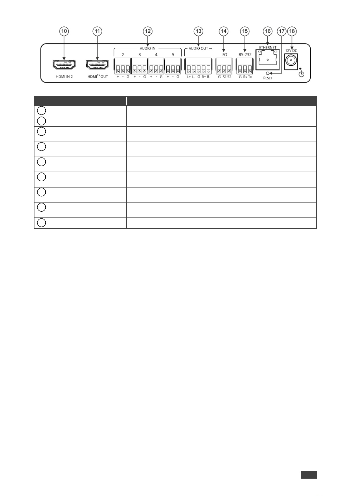
•Wide Range of I/O Formats –Includes 2 HDMI inputs, 1 unbalanced stereo analog input
& 4 balanced analog audio inputs, 2 balanced analog audio outputs, 1 HDMI output, and
1 bidirectional USB plug & play audio port.
•Reliable PoE (Power over Ethernet) Powering –Accepts power from a remote PoE
provider with optional mains powering from connected power adapter.
•Multi-Channel Processing –Provides DSP (Digital Sound Processing) that enables
simultaneous processing of all input and output signals.

Kramer Electronics Ltd.
DSP-62-AEC –Introduction
3
•Easy Installation –Compact DemiTOOLS® fan-less enclosure for surface mounting,
side-by-side mounting of 2 units in a 1U rack space with the recommended rack adapter
or fit in a Kramer T-BUS.
•Easy, Cost-Effective Maintenance –LED indicators for main power, line in/out, mic in,
clipping, and HDMI input selection, enable easy local maintenance and troubleshooting.
Local firmware upgrade via the RS-232 port ensures lasting, field-proven deployment.
•Intuitive and Comprehensive Configuration and Control –Via a powerful, user-friendly
graphic interface, set volume (gain and attenuation) and DSP per input; execute routing
and select line in, mic in, phantom power or line out on each port; configure master level
and more. Control signal routing, volume and other basic settings using API commands
via RS-232 communication transmitted by a PC, touch screen system or other serial
controller.
Flexible Connectivity
•2 HDMI inputs with selection buttons on the front panel.
•1 unbalanced stereo audio source.
•1 USB Type B bi-directional host port.
•1 HDMI output.
•4 balanced audio inputs (mono or mic level).
•One stereo balanced output.
Typical Applications
DSP-62-AEC is ideal for the following typical applications:
•Huddle spaces.
•Small and medium sized meeting rooms.
•Classrooms.
Controlling your DSP-62-AEC
Control your DSP-62-AEC directly via the front panel HDMI select buttons:
•By RS-232 serial commands transmitted by a touch screen system, PC, or other serial
controller.
•Via the Ethernet using built-in user-friendly Web pages.

Kramer Electronics Ltd.
DSP-62-AEC –Defining DSP-62-AEC Digital Sound Processor
4
Defining DSP-62-AEC Digital
Sound Processor
This section defines DSP-62-AEC front and rear panels.
Figure 1: DSP-62-AEC Digital Sound Processor Front Panel
#
Feature
Function
SETUP DIP-switches
For factory use only.
HDMI IN 1 Button
Press to select HDMI IN 1 input (on the front panel).
HDMI IN 2 Button
Press to select HDMI IN 2 input (on the rear panel).
AUDIO
LEDs
USB IN
Lights green when an audio signal is detected on the input (for
example, if DSP-62-AEC operates as a speaker to a PC).
USB OUT
Lights green when an audio signal is detected on the output (for
example, when DSP-62-AEC operates as a microphone for a PC).
IN (1 to 5)
Lights green when a signal is present, lights red when clipping is
detected. For IN 2 to IN 5, when connecting a microphone and setting
to Mic mode via the embedded Web pages, lights blue.
OUT
Lights green when a signal is present, lights red when clipping is
detected.
AUDIO IN 1 3.5mm Mini
Jack
Connect to an unbalanced stereo audiosource.
USB Type B Bi-Directional
Host Port
Connect to an audio source or acceptor.
HDMI IN 1 Connector
Connect to an HDMI source.
ON LED
Lights green when the device is powered.
1
2
3
4
5
6
7
8
9

Kramer Electronics Ltd.
DSP-62-AEC –Defining DSP-62-AEC Digital Sound Processor
5
Figure 2: DSP-62-AEC Digital Sound Processor Rear Panel
#
Feature
Function
HDMI IN 2 Connector
Connect to an HDMI source.
HDMI™OUT Connector
Connect to an HDMI acceptor.
AUDIO IN 3-pin Terminal
Block Connectors (2 to 5)
Connect to up to 4 mono balanced audio sources (mono or mic level
with selectable 48V).
AUDIO OUT 5-pin Terminal
Block Connector
Connect to a stereo balanced audio acceptor.
I/O Terminal Block
Connectors (S1 to S2)
For future use.
RS-232 (G, Rx, Tx)
Terminal Block Connector
Connect to a PC/serial controller.
ETHERNET RJ-45
Connector
Connect to a PC via a LAN.
RESET Recessed Button
Press and hold while powering the device to reset to factory default
values, including IP settings.
12V DC Power Connector
Connect to the power supply and to the mains electricity.
10
11
12
13
14
15
16
17
18

Kramer Electronics Ltd.
DSP-62-AEC –Mounting DSP-62-AEC
6
Mounting DSP-62-AEC
This section provides instructions for mounting DSP-62-AEC. Before installing, verify that the
environment is within the recommended range:
•Operation temperature –0to 40C (32 to 104F).
•Storage temperature –-40to +70C (-40 to +158F).
•Humidity –10% to 90%, RHL non-condensing.
Caution:
•Mount DSP-62-AEC before connecting any cables or power.
Warning:
•Ensure that the environment (e.g., maximum ambient temperature & air flow) is
compatible for the device.
•Avoid uneven mechanical loading.
•Appropriate consideration of equipment nameplate ratings should be used for avoiding
overloading of the circuits.
•Reliable earthing of rack-mounted equipment should be maintained.
Mount DSP-62-AEC in a rack:
•Use the recommended rack adapter
(see www.kramerav.com/product/DSP-62-AEC).
Mount DSP-62-AEC on a surface using one of the following
methods:
•Attach the rubber feet and place the unit on a flat surface.
•Fasten a bracket (included) on each side of the unit and attach it to
a flat surface. For more information go to
www.kramerav.com/downloads/DSP-62-AEC.
Mount DSP-62-AEC inside a TBUS (for example, the TBUS-10XL):
•Use the designated TBUS frame, to mount DSP-62-AEC inside the TBUS-10XL
(see www.kramerav.com/downloads/TBUS-10XL).

Kramer Electronics Ltd.
DSP-62-AEC –Connecting DSP-62-AEC
7
Connecting DSP-62-AEC
Always switch off the power to each device before connecting it to your DSP-62-AEC. After
connecting your DSP-62-AEC, connect its power and then switch on the power to each
device.
Figure 3: Connecting to the DSP-62-AEC
To connect DSP-62-AEC as illustrated in the example in Figure 3:
1. Connect an unbalanced stereo audio source (for example, an MP3 device) to the AUDIO
IN 1 3.5mm mini jack .
2. Connect a USB source (for example, a laptop) to the USB Host port .
3. Connect an HDMI source (for example, a Blu-ray player) to the HDMI IN 1 connector
.
4. Connect an HDMI source (for example, a laptop) to the HDMI IN 2 connector
.
5. Connect up to 4 balanced mono audio sources (for example, microphones) to the
AUDIO IN 3-pin terminal block connectors .
6. Connect the HDMI OUT connector to an HDMI acceptor (for example, a display).
7. Connect the AUDIO OUT 5-pin terminal block connector to a balanced stereo
acceptor (for example, a powered speaker).
8. Connect a control system to the ETHERNET RJ-45 port .
9. Connect the 12V DC power adapter to DSP-62-AEC and to the mains electricity (not
shown in Figure 3).
6
7
8
10
12
11
13
11

Kramer Electronics Ltd.
DSP-62-AEC –Connecting DSP-62-AEC
8
Connecting the Output to a Balanced/Unbalanced
Stereo Audio Acceptor
The following are the pinouts for connecting the output to a balanced or unbalanced stereo
audio acceptor:
Figure 4: Connecting to a Balanced Stereo Audio
Acceptor
Figure 5: Connecting to an Unbalanced Stereo Audio
Acceptor
Connecting to DSP-62-AEC via RS-232
You can connect to DSP-62-AEC via an RS-232 connection using, for example, a PC.
DSP-62-AEC features an RS-232 3-pin terminal block connector allowing the RS-232 to
control DSP-62-AEC.
Connect the RS-232 terminal block on the rear panel of DSP-62-AEC to a PC/controller, as
follows:
From the RS-232 9-pin D-sub serial port connect:
•Pin 2 to the TX pin on the DSP-62-AEC RS-232 terminal
block
•Pin 3 to the RX pin on the DSP-62-AEC RS-232 terminal
block
•Pin 5 to the G pin on the DSP-62-AEC RS-232 terminal
block
RS-232 Device DSP-62-AEC
15

Kramer Electronics Ltd.
DSP-62-AEC –Operating and Controlling DSP-62-AEC
9
Operating and Controlling
DSP-62-AEC
Using the Front Panel
DSP-62-AEC front panel includes:
•Two selection buttons for HDMI IN 1 and HDMI IN 2.
•One USB IN LED to indicate that an audio source is received from the USB host port
(green) and one USB OUT LED to indicate that an audio signal is sent to an
acceptor.
•5 Audio IN LEDs to indicate that a signal is present (green), clipping is detected (red),
and for LEDs 2 to 5, that a microphone is connected (blue).
•One AUDIO OUT LED to indicate that a signal is present (green) or clipping is detected
(red).
•SETUP DIP-switches FOR FACTORY USE ONLY.
Operating via Ethernet
You can connect to DSP-62-AEC via Ethernet using either of the following methods:
•Directly to the PC using a crossover cable (see Connecting Ethernet Port Directly to a
PC on page 9).
•Via a network hub, switch, or router, using a straight-through cable (see Connecting
Ethernet Port via a Network Hub on page 11).
If you want to connect via a router and your IT system is based on IPv6, speak to your IT
department for specific installation instructions.
Connecting Ethernet Port Directly to a PC
You can connect the Ethernet port of DSP-62-AEC directly to the Ethernet port on your PC
using a crossover cable with RJ-45 connectors.
This type of connection is recommended for identifying DSP-62-AEC
with the factory configured default IP address.
After connecting DSP-62-AEC to the Ethernet port, configure your PC as follows:
1. Click Start > Control Panel > Network and Sharing Center.
2. Click Change Adapter Settings.
3. Highlight the network adapter you want to use to connect to the device and click Change
settings of this connection.
4
4
1

Kramer Electronics Ltd.
DSP-62-AEC –Operating and Controlling DSP-62-AEC
10
The Local Area Connection Properties window for the selected network adapter appears
as shown in Figure 6.
Figure 6: Local Area Connection Properties Window
4. Highlight either Internet Protocol Version 6 (TCP/IPv6) or Internet Protocol Version 4
(TCP/IPv4) depending on the requirements of your IT system.
5. Click Properties.
The Internet Protocol Properties window relevant to your IT system appears as shown in
Figure 7 or Figure 8.
Figure 7: Internet Protocol Version 4 Properties Window

Kramer Electronics Ltd.
DSP-62-AEC –Operating and Controlling DSP-62-AEC
11
Figure 8: Internet Protocol Version 6 Properties Window
6. Select Use the following IP Address for static IP addressing and fill in the details as
shown in Figure 9.
For TCP/IPv4 you can use any IP address in the range 192.168.1.1 to 192.168.1.255
(excluding 192.168.1.39) that is provided by your IT department.
Figure 9: Internet Protocol Properties Window
7. Click OK.
8. Click Close.
Connecting Ethernet Port via a Network Hub or Switch
You can connect the Ethernet port of DSP-62-AEC to the Ethernet port on a network hub or
using a straight-through cable with RJ-45 connectors.
Configuring Ethernet Port
You can set the Ethernet parameters via the embedded Web pages.

Kramer Electronics Ltd.
DSP-62-AEC –Using Embedded Webpages
12
Using Embedded Webpages
The DSP-62-AEC can be operated remotely using the embedded webpages. The webpages
are accessed using a Web browser and an Ethernet connection (see Browsing the
DSP-62-AEC Webpages on page 12).
Before attempting to connect:
•Perform the procedures in Operating via Ethernet on page 9.
•Ensure that your browser is supported.
The following operating systems and Web browsers are supported:
Operating Systems
Versions
Windows 7
Chrome
Windows 10
Chrome
Mac
Chrome
Some features might not be supported by some cellphone operating systems.
The DSP-62-AEC webpage enables performing the following functions:
•Using the Top Status Bar on page 13.
•Processing Audio Signals on page 16.
•Routing Inputs to Outputs on page 31.
•Mixing Audio Signals on page 35.
•Defining Audio Settings on page 39.
•Defining Video Settings on page 40.
•Defining General Settings on page 41.
•Viewing Device Information on page 50.
Some of the same tasks can be carried out via DSP, Matrix and Mixer pages, for your
convenience. For example, you can link analog input and output pairs through any of these 3
pages.
Browsing the DSP-62-AEC Webpages
To browse the DSP-62-AEC webpages:
1. Open your Internet browser.
2. Type the IP Address of the device in the Address bar of your browser. For example, the
default IP Address:
3. The authentication page appears.

Kramer Electronics Ltd.
DSP-62-AEC –Using Embedded Webpages
13
4. Enter the Username and Password (Admin/Admin, by-default):
Figure 10: Embedded Webpages Authentication
5. Click Sign in.
The Main webpage appears.
Figure 11: DSP-62-AEC Main Page with the Navigation List on Left
6. Click the desired item in the navigation pane to set and control the device.
Using the Top Status Bar
Use the top status bar to perform the following functions:
•Viewing Current Analog I/O Configuration and Preset Name on page 14.
•Changing Security Settings on page 14.
•Entering/exiting full-screen display view by clicking the display-view icon ( / ).

Kramer Electronics Ltd.
DSP-62-AEC –Using Embedded Webpages
14
Viewing Current Analog I/O Configuration and Preset Name
The center of the menu bar in every webpage shows the analog I/O setup, the preset name
and the status of the setup.
The indication light displays:
•Green when the actual settings are
unmodified.
Figure 12: Analog and/or Preset Status Unmodified
•Yellow when actual settings have been
modified and not saved into a preset.
Figure 13: Analog and/or Preset Status modified
To save a modified preset (yellow indication light):
1. Click the preset status area. The A/V settings page appears (see Figure 46).
2. Follow the instructions in Defining Audio Settings on page 39.
Changing Security Settings
You can easily disable or enable the webpages security using the lock icon. When security is
disabled, you do not need to enter a password to access the webpages. When security is
enabled, you do. For information about the default login credentials, see Default
Communication Parameters on page 53. For information about changing the default login
credentials, see Setting Access Security on page 47.
To disable security settings:
1. Click the lock icon ( ) indicating that security is enabled.
The following message appears:
Figure 14: Disabling Security Message
2. Type the current password (Admin, by default).
3. Click OK.
Security is disabled.
To enable security settings:
•Click the security disabled icon ( ).

Kramer Electronics Ltd.
DSP-62-AEC –Using Embedded Webpages
15
Viewing the Matrix Area
The matrix area in the DSP page shows the inputs that are currently routed to the outputs.
Figure 15: DSP Page –Matrix Area
Clicking an IN or OUT button or a signal processing module (for example, Exp), highlights the
routing path.
Figure 16: Matrix Area –Routing Path
When opening the processing view, the sliders of the Inputs routed to the outputs appear.
Figure 17: Processing View –Inputs Routed to Outputs

Kramer Electronics Ltd.
DSP-62-AEC –Processing Audio Signals
16
Processing Audio Signals
Use the DSP page to process the input and output signals and present an overall view of your
session, including analog and digital in-out connections (in the Matrix area), using pre-matrix
and post-matrix modules.
In general:
•Click the Matrix area to enter the Matrix page (see Routing Inputs to Outputs
on page 31).
•Click an input, output or any module to open its process view and configure that item.
The DSP page enables performing the following functions:
•Linking Analog Inputs and Outputs on page 16.
•Processing a Signal on page 16.
Linking Analog Inputs and Outputs
Analog inputs and outputs can be linked in predefined pairs to balance stereo analog sources
and acceptors. When linked, signal chain modules are set for both channels simultaneously.
To link an analog audio pair:
1. In the Navigation pane, click DSP. The DSP (Main) page appears.
You can also link audio analog audio pairs via the Matrix page, and Mixer page.
2. Click the link on the side of the ports (IN 4 and IN 5 in this example).
Figure 18: DSP Page –Linking Analog Audio Ports
The selected inputs are linked.
Processing a Signal
Access processing view by clicking an input / output button or a filtering tool in the DSP
session view. Use processing view to configure the selected audio signal.
Different port types have different processing modules.
In general:
•Toggle the (off) / (on) button to enable/disable a processing module.
The module is enabled while it is set to On and disabled when set to Off.

Kramer Electronics Ltd.
DSP-62-AEC –Processing Audio Signals
17
•Change a port name by clicking the name area and entering the new one.
•In the processing view, the module appears at the center and input/output volume sliders
appear to the left/right (for further information, see Input / Output Channels Operation
on page 17).
•Adjust configuration knob by clicking and holding the mouse then moving it up or down,
or enter the parameter value below the knob and press Enter on your keyboard to apply.
•Reset a configuration knob to its default parameter value, by clicking the mouse within
the knob area while pressing Ctrl on your keyboard.
•The parameter value always appears below the knob or slider.
•A selected input or output button appears with a white rim.
•A selected processing tool button appears with a distinctive color.
•An enabled processing tool button appears with a distinctively colored rim.
Processing modules enable performing the following functions:
•Input / Output Channels Operation on page 17.
•Pre-Matrix Signal Processing on page 18.
•Post-Matrix Signal Processing on page 28.
Input / Output Channels Operation
This section describes the function of the input and output sliders (the examples in this
section, showing the inputs, apply also to outputs).
Level Measurement Indicators:
The audio signal enters the digital system at a
certain level and is measured in dBFS units
(dB relative to full scale, the maximum value).
•Maximum level indicator –shows the
highest registered level (in RMS) and
can change only if a higher level is
detected.
Click the indicator to reset to the current
maximum value.
•0dBFS –refers to the maximum signal
level that can enter the system. signal
levels higher than the system limit are
clipped.
•Current maximum level indicator –
displays the current maximum level and
holds it until a higher value is detected.
Figure 19: Level Measurement Indicators

Kramer Electronics Ltd.
DSP-62-AEC –Processing Audio Signals
18
Gain/Attenuation Fader
•Maximum level –15dB is the maximum
gain.
•Unity gain –when volume fader is set to
0dB, the input level is not changed.
•Volume fader –slide to increase or
decrease the audio level.
•Minimum level –-100dB is the
maximum attenuation.
•Current fader position –shows the
current position of the fader. You can
also type the desired volume level into
this box and press Enter on your PC.
Figure 20: Channel Fader
Pre-Matrix Signal Processing
This section describes the input pre-matrix signal processing of the input audio signal. The
input fader always appears to the left.
Pre-matrix enables adjusting the following parameters:
•Adjusting Analog Input Parameters on page 18.
•Adjusting USB Digital Input Parameters on page 20.
•Adjusting HDMI Digital Input Parameters on page 21.
•Adjusting Signal Generator Input Parameters on page 22.
•Using Expander Module on page 22.
•Using HPF (High Pass Filter) Module on page 23.
•Using Compression Module on page 24.
•Using Equalizer Module on page 25.
•Using Gain Module on page 26.
•Using AEC Module on page 27.
•Using Delay Module on page 28.
Adjusting Analog Input Parameters
See Input / Output Channels Operation on page 17 to understand the function of the slider.
IN 1 is used as an example in this section.
To adjust analog input parameters:
1. In the Navigation pane, click DSP. The DSP (Main) page appears.
2. Click IN 3.
The IN 3 processing page appears.
Other manuals for DSP-62-AEC
1
Table of contents
Other Kramer Recording Equipment manuals

Kramer
Kramer KT-2010 User manual

Kramer
Kramer VS-12DPIR User manual

Kramer
Kramer TP-576 User manual

Kramer
Kramer VA-10 User manual

Kramer
Kramer PT-102VN User manual

Kramer
Kramer FC-202NET User manual

Kramer
Kramer VA-15XL User manual

Kramer
Kramer DSP-62-UC User manual

Kramer
Kramer DigiTOOLS 6809HD User manual

Kramer
Kramer 401DXL User manual

Kramer
Kramer FC-404NET User manual

Kramer
Kramer DSP-1 User manual

Kramer
Kramer WAS-3 User manual

Kramer
Kramer VS-12DPIR User manual

Kramer
Kramer RC-3TBU User manual

Kramer
Kramer DigiTOOLS 6808 User manual

Kramer
Kramer DSP-1 User manual

Kramer
Kramer VA-256 User manual

Kramer
Kramer SP-1G User manual

Kramer
Kramer DSP-1 User manual