OTC Tools 5292 User manual
© Bosch Automotive Service Solutions LLC
Sheet No.
Issue Date: Rev. B, April 28, 2014
Form No. 570918
Under Axle Jack
Max. Capacity: 27.5 Tons
655 Eisenhower Drive
Owatonna, MN 55060 USA
Phone: (507) 455-7000
Tech. Serv.: (800) 533-6127
Fax: (800) 955-8329
Order Entry: (800) 533-6127
Fax: (800) 283-8665
International Sales: (507) 455-7223
Fax: (507) 455-7063
Parts List &
Operating Instructions
for: 5292
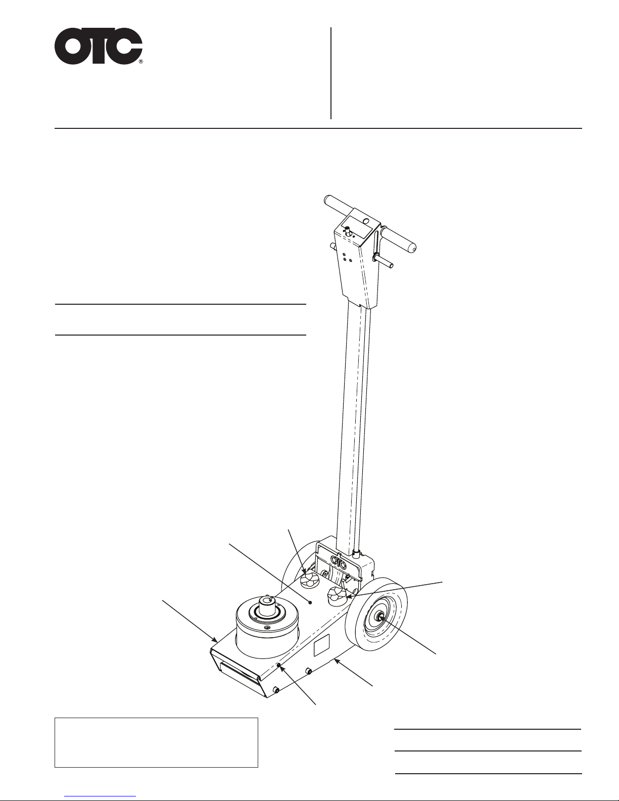
No. 5292 Under Axle Jack is an air-operated lifting
device designed for jacking loaded trailers and trucks
using the manufacturer's recommended lift points on
the chassis.
Item Part
No. No. Qty. Description
1 ì1 Tall Saddle
2 ì2 Retaining Ring
3 542068 1 Base
4 14456 2 Screw
(10-24 x .500; self-tapping;
apply Loctite
®
277
[or equivalent] and torque
to 30 ft. lbs.)
5 542073 1 Base Cover Plate
6 ì1Logo / Warning Decal
7 ì1 Short Saddle
1
2
3
4
5
6
1 of 5
7
Items marked with a star (ì) are
contained in replacement parts kits.
See sheet 3 of 5, back.
Parts List & Operating Instructions Form No. 570918, Sheet 1 of 5, Back
910
11
8
13
14, 15, 16, 17
18
Item Part
No. No. Qty. Description
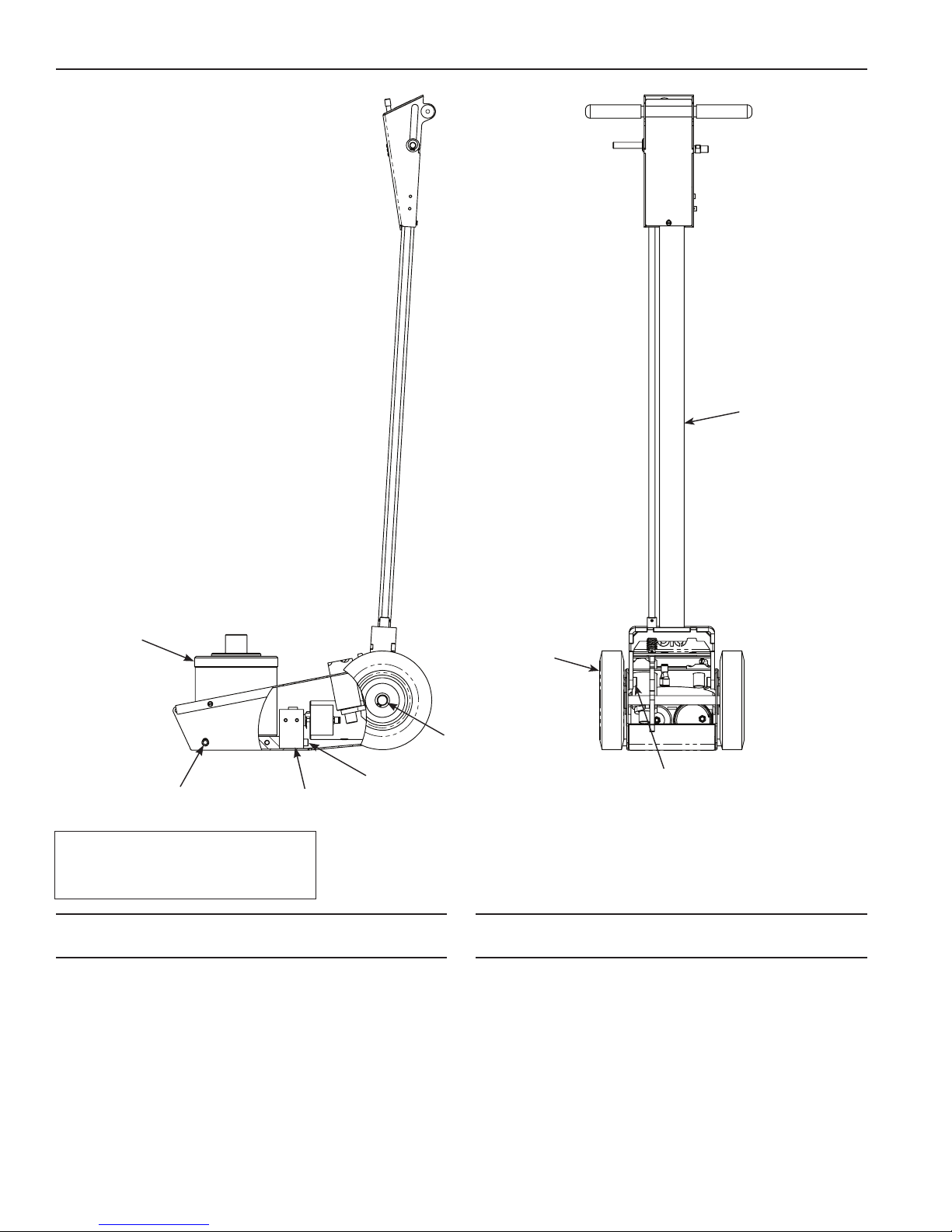
8 542069 1 Hydraulic Assembly
9
ì
4 Socket Hd. Cap Screw (.375–16;
Apply Loctite®277 [or equivalent]
and torque to 30 ft. lbs.)
10 568052 1 Air Pump and Motor Assembly
(Assembly includes o-rings;
See parts list on sheet 3)
11
ì
2 Socket Hd. Cap Screw (.375–16;
Apply Loctite®277 [or equivalent]
and torque to 30 ft. lbs.)
12
ì
2 External Retaining Ring
13
ì
2 Wheel
14
ì
2 Shoulder Bolt
15
ì
4 Washer
16
ì
2 Lockwasher (3/8)
17
ì
2 Hex Nut (3/8-16)
18 570911 1 Handle Assembly
(parts list on sheet 2)
Parts included but not shown
554332 2 Warning Decal
Item Part
No. No. Qty. Description
Items marked with a star (ì) are
contained in replacement parts kits.
See sheet 3 of 5, back.
12
© Bosch Automotive Service Solutions LLC
Sheet No.
Issue Date: Rev. B, April 28, 2014
Parts List & Operating Instructions Form No. 570918
Item Part
No. No. Qty. Description
20 554333 1 Control Decal
21
ì
2 Handle Grip
22
ì
3 Button Hd. Cap Screw (8-32)
23 563599 1 Handle Adapter Pin
24
ì
1 Retaining Ring
25
ì
1 Washer (1/2")
26 542070 1 Handle Lock Rod
27 570914 1 Air Switch Knob
28
ì
1 Screw (10-24 x .500)
29 568399 1 Handle Weldment
30
ì
1 Compression Spring
31
ì
2 Roll Pin
32 542064 1 Cover Plate
33 555032 - Tubing (1092 mm length)
34
ì
3 Push-to-Connect Fitting
35 554112 1 Valve
36 555032 - Tubing (235 mm length)
37
ì
3 Locknut (M4 x .70)
38
ì
1 Nipple (.250 NPT x .125 NPT)
39
ì
- Tubing (63.5 mm length)
40
ì
1 Socket Hd. Cap Screw
41 553772 1 Vacuum Generator Assembly
(see parts list below)
Item Part
No. No. Qty. Description
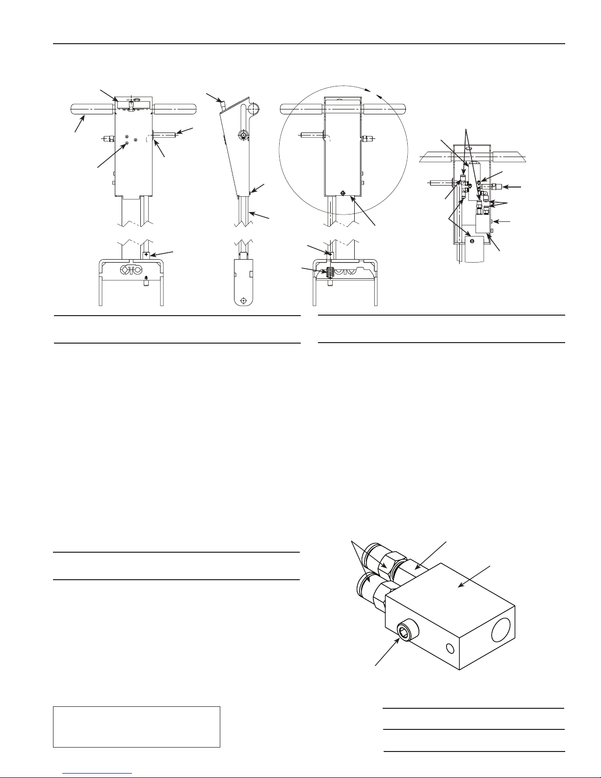
No. 570911 Handle Assembly
2 of 5
x
DETAIL x
21
22
27
24, 25 37
20
34
23
26
28
29
32
35
39
40
38
No. 553772 Vacuum Generator Assembly
Item Part
No. No. Qty. Description
45 554113 2 Push-to-Connect Fitting
(8 mm)
46 566336 1 Venturi Nozzle
47
ì
1 O-ring (nitrile)
48 566335 1 Venturi Valve Block
50 554114 1 Socket Head Cap Screw
51
ì
1 O-ring (uoroelasomer)
46, 47
48
50, 51
45
31
30
Items marked with a star (ì) are
contained in replacement parts kits.
See sheet 3 of 5, back.
33
36
41
DETAIL X
NOTE: Wrap 555032 tubing with
570915 black air line tube to protect it
within the handle assembly.

Parts List & Operating Instructions
No. 542069 Hydraulic Assembly
54
55
56
57
52, 53
58, 59
60
61
62
63
64
65
66
67, 68
Item Part
No. No. Qty. Description
52
ì
1 Fill Plug
53
ì
1 O-ring
54 548124 1 Reservoir Cap
55 542080 1 Base
56
ì
1 Push-to-Connect Fitting
57
ì
1 ExhaustMufer
58
ì
1 Screen Filter
59
ì
1 Filter Retainer
60
ì
1 Seal
61
ì
1 Wear Ring
62
ì
1 O-ring
63 558437 1 Piston Wear Ring
64
ì
1 U-cup
65 566495 1 Gland Nut
(torque to 100 ft-lbs)
66
ì
2 Seal
67
ì
1 Spring
68
ì
1 Dowel Pin
69 542085 1 Extension Screw
70 548123 1 Reservoir Tube
71 542084 1 Piston
72
ì
1 O-ring
73
ì
1 External Retaining Ring
Item Part
No. No. Qty. Description
Form No. 570918, Sheet 2 of 5, Back
69
71
66
70
73
Items marked with a star (ì) are
contained in replacement parts kits.
See sheet 3 of 5, back.
72

© Bosch Automotive Service Solutions LLC
Sheet No.
Issue Date: Rev. B, April 28, 2014
Parts List & Operating Instructions Form No. 570918
Item Part
No. No. Description
74 555014 Block Assembly
75 555016 Air Motor
76 555017 Air Motor Plunger Assembly
77 572561 Release Valve
k555018 Air Motor Seal Kit
3 of 5
No. 568052 Air Motor Assembly
75
74
75
77
76
77 74
k
k
k
k
k
k
k
k
k
k
k

Parts List & Operating Instructions
Item
No. Qty. Description
No. 563502
Fastener Kit
9 4 Socket Hd. Cap Screw
(.375–16)
11 2 Socket Hd. Cap Screw
(Loctite®; torque to 30 ft.lbs.)
14 2 Shoulder Bolt
15 6 Washer
16 2 Lockwasher (3/8)
17 2 Hex Nut (3/8-16)
22 3 Button Hd. Cap Screw (8-32)
25 1 Washer (1/2 in.)
34 3 Screw (10-24 x .500)
No. 563503
Handle Hardware Kit
34 3 Push-to-Connect Fitting
37 3 Locknut (M4 x .70)
38 1 Nipple
(.250 NPT x .125 NPT)
33 6.5 ft. Tubing
36
39
40 1 Socket Hd. Cap Screw
No. 563504
Handle Grip Kit
21 2 Handle Grip
No. 563505
Hardware Kit
1 Warning Decal
2 2 Retaining Ring
6 1 Logo / Warning Decal
24 1 Retaining Ring
30 1 Spring
31 2 Roll Pin
67 1 Spring
68 1 Dowel Pin
1 Y-tting
No. 563506
Seal Repair Kit
2 O-ring
47 1 O-ring (nitrile)
51 1 O-ring (uoroelasomer)
52 1 Fill Plug
53 1 O-ring
56 1 Push-to-Connect Fitting
57 1 ExhaustMufer
58 1 Screen Filter
59 1 Filter Retainer
60 1 Seal
61 1 Wear Ring
62 1 O-ring
64 1 U-cup
66 2 Seal
72 1 O-ring
73 1 External Retaining Ring
No. 563507
Saddle Kit
1 1 Tall Saddle
7 1 Short Saddle
No. 563508
Wheel Repair Kit
12 2 Retaining Ring
13 2 Wheel
Item
No. Qty. Description
Item
No. Qty. Description
Form No. 570918, Sheet 3 of 5, Back
This document contains product parts lists as well as
information regarding operation and maintenance.
Items listed in the parts list have been carefully tested
and selected by OTC.
Therefore: Use only OTC replacement parts.
Product questions may be directed to the OTC Technical
Services Department at (800) 533-6127. Get parts at OTCparts.com.
© Bosch Automotive Service Solutions LLC
Sheet No.
Issue Date: Rev. B, April 28, 2014
Parts List & Operating Instructions Form No. 570918
Assembly and Setup
1. Remove the wheels from the jack, leaving the spacer washers in place.
2. Using the hardware supplied, assemble the handle to the jack base.
3. Place the wheels back onto the wheel shaft. Verify the wheels do not rub on the frame and secure in place
with a snap ring.
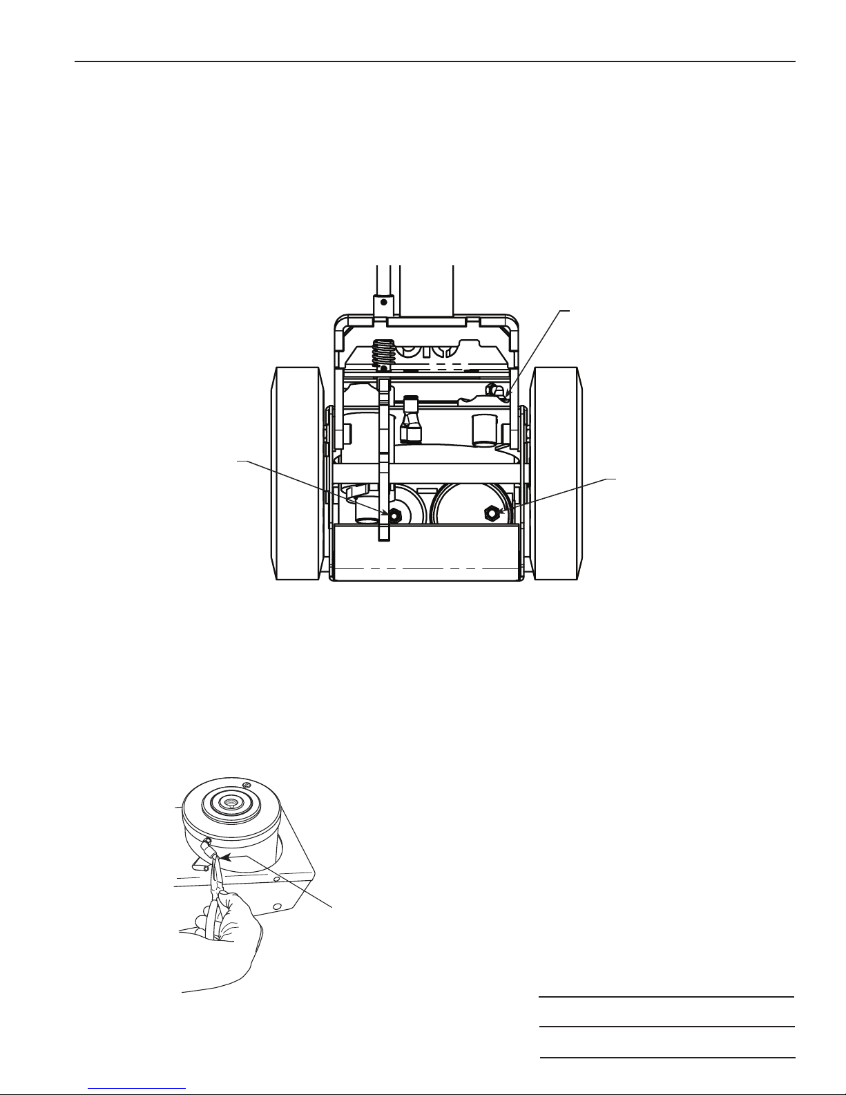
4. Connect the hoses as shown in Figure 1.
Figure 1
View from back of jack
Connect end of blue
hose from Y tting here.
Connect end of blue
hose from Y tting
here.
Connect black hose
from handle here.
5. Refer to Figure 2 and the following steps to connect the hydraulic assembly.
•Locatethettingonthehydraulicassembly.
•Pullthettingcollarbackandremovethepin.
• Connect the blue hose from the air motor.
Figure 2
Remove pin
4 of 5

Parts List & Operating Instructions
Safety Precautions
CAUTION: To prevent personal injury and damage to equipment,
•Study, understand, and follow all instructions before operating this device.
•Wear protective eyewear that meets the requirements of ANSI Z87.1 and OSHA.
•Do not exceed the rated capacity of the jack.
•Use the jack only on a hard, level surface.
•This jack is a lifting device only. Immediately after lifting, support the vehicle with
appropriate means.
•Do not move or dolly the vehicle while it is on the jack.
• Lift only on areas of the vehicle as specied by the vehicle manufacturer.
•No alterations shall be made to this product.
Operating Instructions
1. Lubricate the air inlet on the jack with 1/2 oz. clean lubricating oil; lack of oil can cause pump
malfunction.
2. Connect the air supply. (90 – 120 psi of clean, dry air is required for the capacity of this jack.)
3.Setthevehicle’sparkingbrakesand/orblockthewheels.
4.Positionthejackunderthevehicleatthevehiclemanufacturer’srecommendedliftingpointonthechassis.
5. Move the air valve lever to the right to raise the jack saddle until it touches the vehicle. Check the placement
of the saddle lugs. Finish lifting the vehicle.
6. Place approved safety stands under the vehicle at points that will provide stable support. Before making
repairs, lower the vehicle onto the safety stands by moving the air valve lever to the left to retract the
cylinder. Note: Keep the air supply attached to the jack.
Bleeding Air from the Under Axle Jack
Air can accumulate within a hydraulic system during shipment or after prolonged use. This entrapped air
causes the jack to respond slowly or feel “spongy.” To remove the air:
1. Connect the air supply to the jack.
2. Move the air valve lever to the left until the cylinder is fully retracted.
3. Move the air valve lever to the right until the cylinder is fully extended.
4.Repeatsteps2–3veormoretimes.
Form No. 570918, Sheet 4 of 5, Back

© Bosch Automotive Service Solutions LLC
Sheet No.
Issue Date: Rev. B, April 28, 2014
Parts List & Operating Instructions Form No. 570918
Preventive Maintenance
Important: The greatest single cause of failure in hydraulic units is dirt. Keep the under axle jack clean
and well lubricated to prevent foreign matter from entering the system. If the jack has been exposed
to rain, snow, sand, or grit, it must be cleaned before it is used.
1. Store the jack in a well-protected area where it will not be exposed to corrosive vapors, abrasive dust, or
any other harmful elements.
2. Regularly lubricate the moving parts.
3. Replace the oil in the reservoir at least once per year. To check the oil level, disconnect the air supply, place
theunderaxlejackonlevelground,andcompletelyretracttheram.Removethellerplug/dipstick,wipe
it clean, and reinstall it, threading it in all the way. Remove the dipstick again and note the oil level. The oil
level should be between the two marks on the dipstick. Add or remove approved anti-wear hydraulic jack
oil as needed, and install the dipstick. CAUTION: The use of alcohol, hydraulic brake uid, detergent
motor oil, or transmission oil could damage the seals and result in jack failure.
4. Inspect the jack before each use. Take corrective action if any of the following problems are found:
a. Cracked or damaged housing d. Scored or damaged piston rod
b. Excessive wear, bending, or other damage e. Loose hardware
c.Leakinghydraulicuid f.Modiedoralteredequipment
Troubleshooting Guide
Repairproceduresmustbeperformedinadirt-freeenvironmentbyqualiedpersonnelwhoarefamiliar
with this equipment.
Trouble Cause Solution
Erratic action 1. Air in system.
2. Oil viscosity too high.
3. Internal leakage in cylinder.
4. Cylinder sticking or binding.
1. Follow the instructions in this document, "Bleeding
Air from the Under Axle Jack".
2. Change to a lower viscosity oil.
3. Replace worn packings. Look for excessive
contamination or wear.
4. Look for dirt, gummy deposits, or leaks. Check for
misalignment, worn parts, or defective packings.
Jack does not lift 1. Low / no oil in reservoir.
2. Air-locked system.
3. Load is above capacity of jack.
4. Delivery valve and / or bypass valve not
working correctly.
5. Packing worn out or defective.
1. Fill with oil and bleed system.
2. Follow the instructions in this document, "Bleeding
Air from the Under Axle Jack".
3. Use correct equipment.
4. Clean to remove dirt or foreign matter. Replace oil.
5. Replace power unit.
Jack lifts only partially 1. Not enough oil. 1. Check oil level.
Jack advances slowly 1. Low air pressure.
2. Seals are leaking.
3. Pump not working correctly.
1. Adjust air pressure to 90–175 psi.
2. Take jack to OTC authorized service center for repair.
3. Take jack to OTC authorized service center for repair.
Jack lifts load, but does not hold 1. Cylinder packing is leaking.
2. Valve not working correctly (delivery,
release, or bypass).
3. Air-locked system.
1. Replace seals.
2. Take jack to OTC authorized service center for repair.
3. Bleed system.
Jack leaks oil 1. Worn or damaged seals. 1. Take jack to OTC authorized service center for repair.
Jack will not retract 1. Release valve is closed. 1. Open or clean release valve.
Jack retracts slowly 1. Cylinder damaged internally. 1. Take jack to OTC authorized service center for repair.
Sound of air leaking when lever is
in retract position.
1. This is normal.
5 of 5
Table of contents
Other OTC Tools Tools manuals


