OTC Tools 5093B User manual

Sheet No.
Issue Date: Rev. B April 17, 2012
© 2012 SPX
Form No. 560035
Parts List &
Operating Instructions
for: 5093B
655 EisEnhowEr DrivE
owatonna, Mn 55060-0995 Usa
PhonE: (507) 455-7000
tEch. sErv.: (800) 533-6127
Fax: (800) 955-8329
orDEr Entry: (800) 533-6127
Fax: (800) 283-8665
intErnational salEs: (507) 455-7223
Fax: (507) 455-7063
Original Instructions
1 of 3
Description:
Under-axle jack designed to lift
Class 7 and Class 8 vehicles.
Air / Hydraulic
3-Stage Under Axle Jack
Weight: 69.5 kg (153 lbs.)
Explanation of Safety Signal Words
The safety signal word designates the degree or level of hazard seriousness.
DANGER: Indicates an imminently hazardous situation which, if not avoided, will result in death or
serious injury.
WARNING: Indicates a potentially hazardous situation which, if not avoided, could result in death or
serious injury.
CAUTION: Indicates a potentially hazardous situation which, if not avoided, may result in minor or
moderate injury.
CAUTION: Used without the safety alert symbol indicates a potentially hazardous situation which, if not
avoided, may result in property damage.
Maximum Capacity per Stage: 20 / 35 / 65 Metric Tons
22 / 38.5 / 71.6 US Tons
Parts List & Operating Instructions Form No. 560035, Sheet 1 of 3, Back
Safety Precautions
CAUTION: To prevent personal injury and/ or property damage,
•Study, understand, and follow all safety precautions and operating instructions before
using this jack. If the operator cannot read instructions, operating instructions and safety
precautions must be read and discussed in the operator’s native language.
• Onlyqualiedoperatorsmayinstall,operate,adjust,maintain,clean,repair,inspect,or
transport this jack.
•Inspect the condition of the jack before each use; do not use if damaged, altered, or in
poor condition.
•Wear eye protection that meets ANSI Z87.1, CE EN166, AS/NZS 1337, and OSHA
standards.
•The rated capacity for each stage of the jack is shown on the product decal, as well as in
this document. Do not exceed the rated capacity of each stage.
•Use on a hard, level surface with the wheels level.
• Liftonlyonareasofthevehicleasspeciedbythevehiclemanufacturer.
•Center load on jack saddle. Off-center loads can damage seals and cause jack failure.
•This is only a lifting device. Immediately after lifting, support vehicle with appropriate
means.
•Stay clear of a lifted load.
•Do not use this jack for anything other than its intended purpose. Do not use the jack to
move or dolly a vehicle.
•No alteration shall be made to this product.
•Use only those repair parts called out in the replacement parts list in this document. Items
found in the parts list have been carefully tested and selected by OTC.
Sheet No.
Issue Date: Rev. B April 17, 2012
© 2012 SPX
Parts List & Operating Instructions Form No. 560035
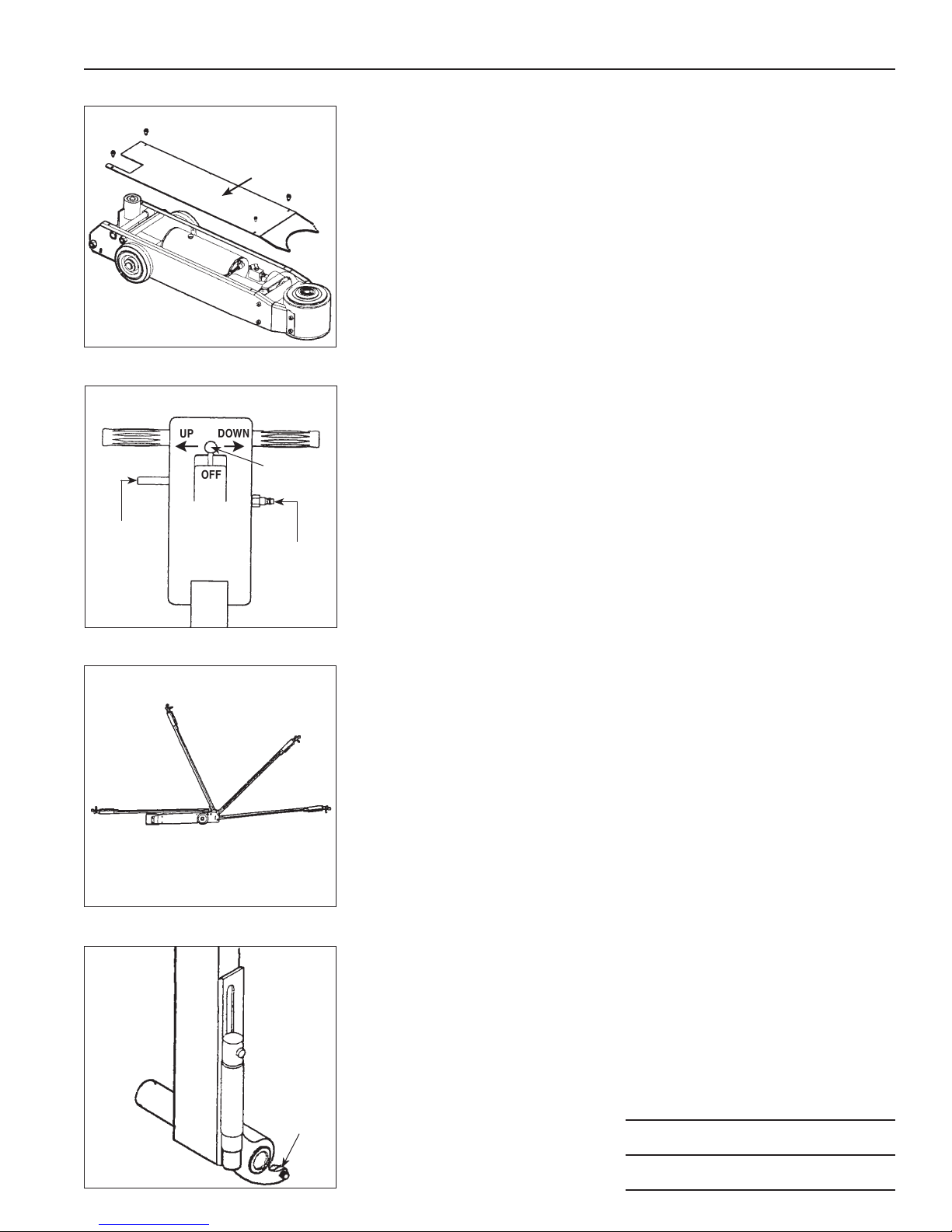
Figure 2
Shop
Air
Control
Lever
Handle
Position
Lever
2 of 3
Setup
1. See Figure 1. Loosen and remove the four screws holding the upper
cover. Remove the upper cover.
2. Note the handle position lever shown in Figure 2. Use the lever to
place the handle in Position 4 (horizontal) as shown in Figure 3.
3. Insert the bolt and washer near the bottom of the handle assembly.
See Figure 4.
Note: When storing the jack for a long period of time, remove the bolt
and washer to place the handle in Position 1.
4. Install the upper cover.
Operating Instructions
1. Verify the control lever is in the OFF position. See Figure 2.
2. Connect shop air supply to the jack. Recommended air pressure is
7–10 BAR (100–145 psi). Install an air lter / lubricator in the shop
air line, because water in the air line will damage the jack.
3. Move the control lever to the UP position to raise the saddle to the
contact point. Move the control lever to OFF.
Note: The extension may be used in the uppermost position if required
to meet the contact point.
4. Check the placement of the jack: lift only on areas of the vehicle as
specied by the vehicle manufacturer; center the load on the jack
saddle; avoid jack wheel obstructions such as gravel, tools, or uneven
expansion joints.
5. Move the control lever to UP to nish lifting the vehicle.
6. Immediately place approved support stands under the vehicle at points
recommended by the vehicle manufacturer. Slowly and carefully lower
the vehicle onto the support stands by pushing the control lever to
the DOWN position.
Bleeding Air from the Jack
Air can accumulate within a hydraulic system during shipment or after
prolonged use. This entrapped air causes the jack to respond slowly or
feel “spongy.” To remove the air:
1.
Move the control lever to DOWN, and hold it there for a few seconds.
2. Move the control lever to UP to complete a load-free lifting cycle.
3. Move the control lever to DOWN to retract the jack pistons. The
pistons should react in a smooth motion; if not, repeat Steps 1–3.
Figure 1
Upper
Cover
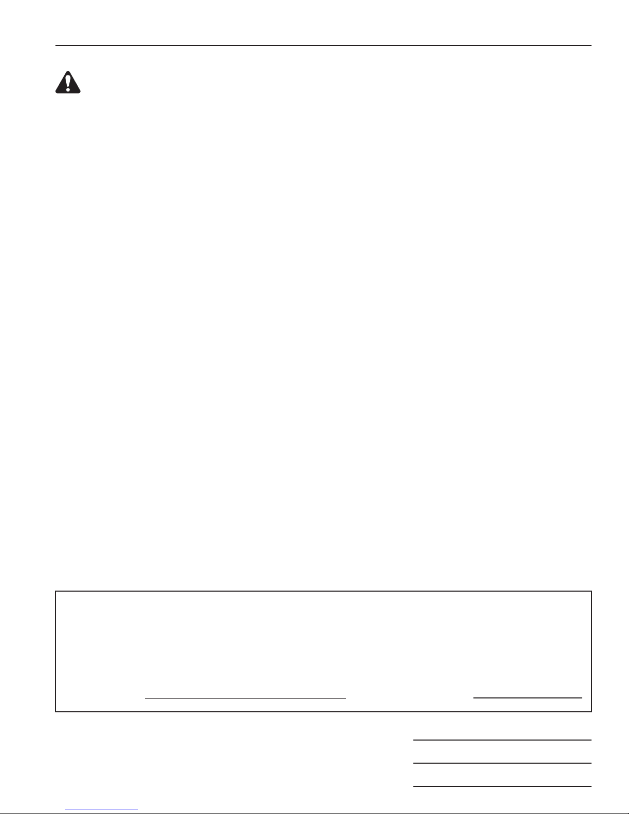
Figure 3
Disengage trigger lever to move handle to
one of four positions:
1) collapsed; 2) storage: 3) movement:
and 4) horizontal.
1
2
3
4
Figure 4
Bolt &
Washer

Parts List & Operating Instructions Form No. 560035, Sheet 2 of 3 Back
Replacement Parts
Item Part
No. No. Description
1 561789 Power Unit
2 561795 Base
3 561794 Piston (64.9 metric tons)
4 561793 Piston (34.9 metric tons)
5 561792 Piston (20 metric tons)
6 561791 Saddle Kit
7 561790 Power Unit Handle
8 561788 Hydraulic Unit Seal Kit
9 561801 Release Valve & Hose Kit
10 561806 Top Cover
11 561807 Frame / Reservoir
9
10
12
11
13
14
15
16
17
9 (blue)
18
19
1
13
14
16
9 (red)
9 (black)
9(green)
1
2
3
4
5
6
7
8
8
8
8
8
8
8
8
8
8
8
8
8
8
8
12 561805 Wheel
13 561798 Valve Body
14 561796 Air Pump
15 561799 Regulator Valve Assembly
16 561797 Regulator
17 561800 Air Valve
18 561803 Handle
19 561802 Air Fitting
20 560806 Extension
Item Part
No. No. Description
20
Sheet No.
Issue Date: Rev. B April 17, 2012
© 2012 SPX
3 of 3
Parts List & Operating Instructions Form No. 560035
Inspection and Maintenance
CAUTION: To prevent personal injury,
• Onlyqualiedpersonnelshallperforminspectionsandrepairstothisjack.
•Before each use, an approved inspector must inspect the jack for bends, cracks, dents, elongated
holes, or missing hardware. If damage is found, discontinue use.
•Use only those repair parts called out in the parts list in this document. Items found in the parts
list have been carefully tested and selected by OTC.
•Disconnect the air supply hose from the jack before perfoming any maintenance or repair procedure.
See Figure 2 for the location of the air supply connection.
Inspection
Before each use, an approved inspector must inspect the jack for bends, cracks, dents, elongated holes, or
missing hardware. If damage is found, discontinue use.
Maintenance
•Periodically lubricate the moving parts of the jack using lubricating oil or grease.
•Use only anti-wear hydraulic jack oil (215 SUS viscosity at 100° F). The use of alcohol, hydraulic brake
uid, or transmission oil could damage the seals in the cylinder and result in jack failure.
•Periodically check the oil level in the cylinder: 1) Retract the pistons completely. 2) Remove the ller plug.
The oil level should be between the two marks on the rod. Rell as needed using approved hydraulic uid.
3) Install the ller plug.
•The greatest single cause of failure in hydraulic units is dirt. Keep the jack clean and well lubricated to
prevent foreign matter from entering the hydraulic system.
•Whenever the jack is not in use, fully retract the pistons to reduce the risk of corrosion.
Repair
When repairing the jack, use only those repair parts called out in the replacement parts list in this
document. Items found in the parts list have been carefully tested and selected by OTC.
Disposal
At the end of the useful life of the jack, dispose of the jack according to all state, federal, and local
regulations.
PRODUCT INFORMATION
Recordserialnumberandyearofmanufactureforfuturereference.Seeproductidentication
label on unit for information.
5093B
Serial Number: Year of Manufacture:
Table of contents
Other OTC Tools Tools manuals


