manuals.online logo
Brands
  1. Home
  2. •
  3. Brands
  4. •
  5. Otter
  6. •
  7. Tent
  8. •
  9. Otter Pro XT Lodge Manual

Otter Pro XT Lodge Manual

Page 1
Otter Pro XT Lodge
Installation and Set-Up Instructions
Otter Pro XT Lodge
FitsMagnumOtterII&ProSledOnly
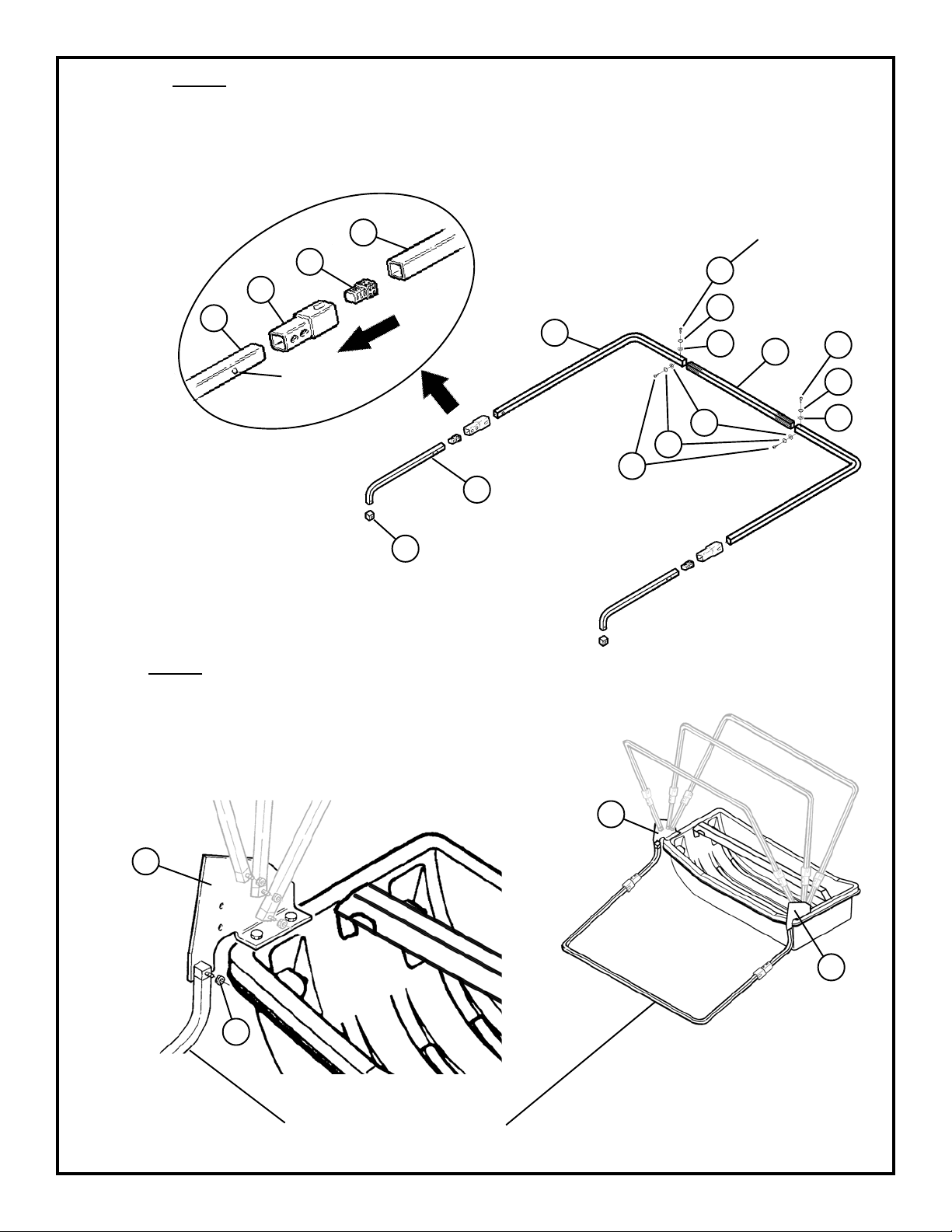
PartsIdentificationandCheckList
PP
PP
PARAR
ARAR
ARTS LISTTS LIST
TS LISTTS LIST
TS LIST
Item #Item #
Item #Item #
Item # QtyQty
QtyQty
Qty Part #Part #
Part #Part #
Part # DescriptionDescription
DescriptionDescription
Description
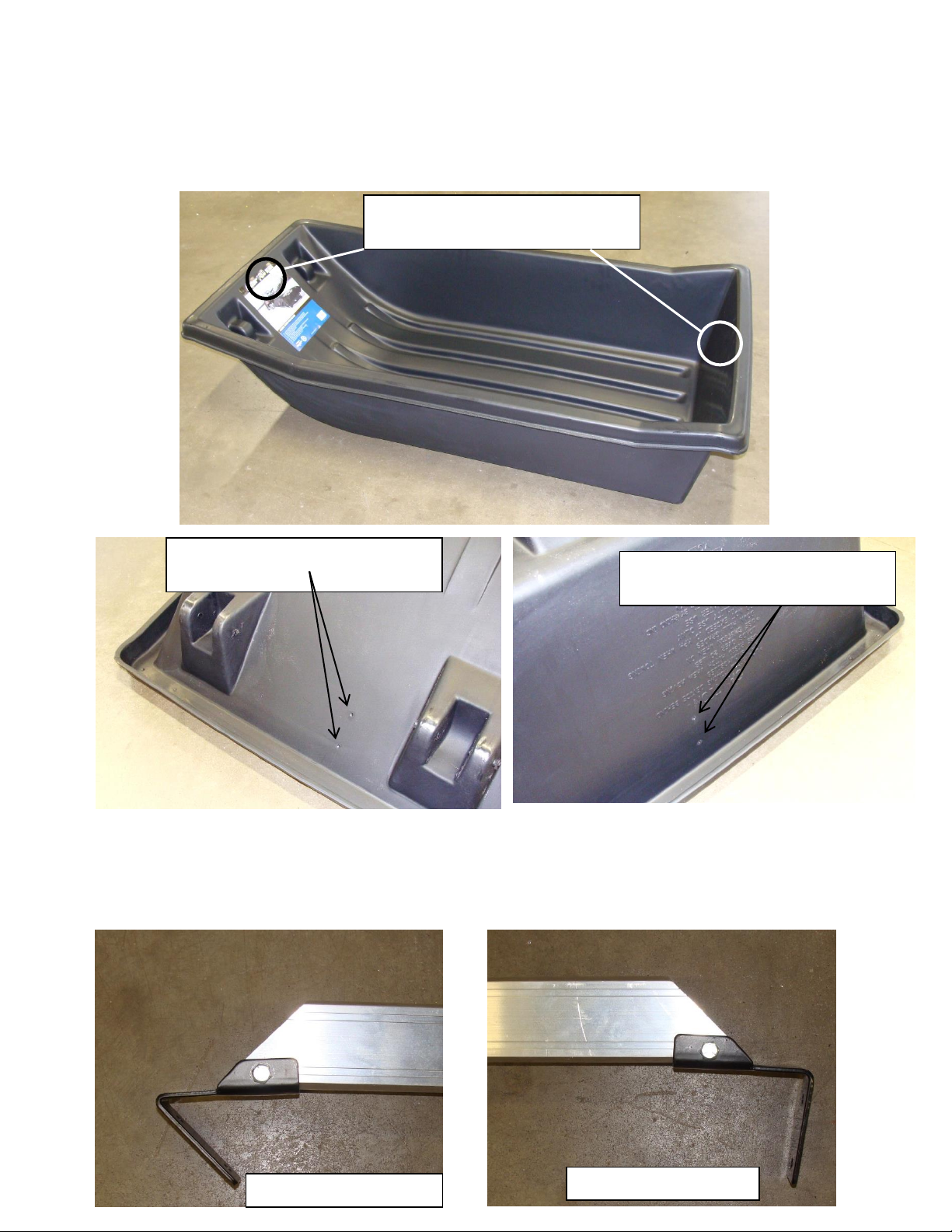
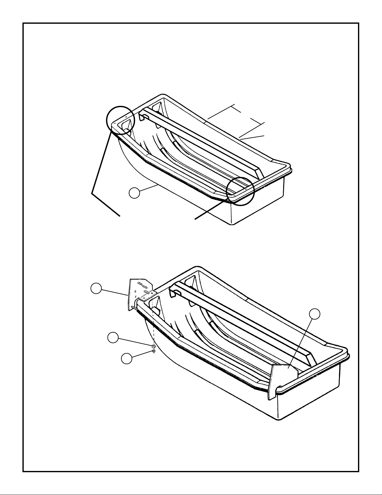
1 1 201067 Sled - Dark Gray
2 1 200967 Tent-XTThermalLodge
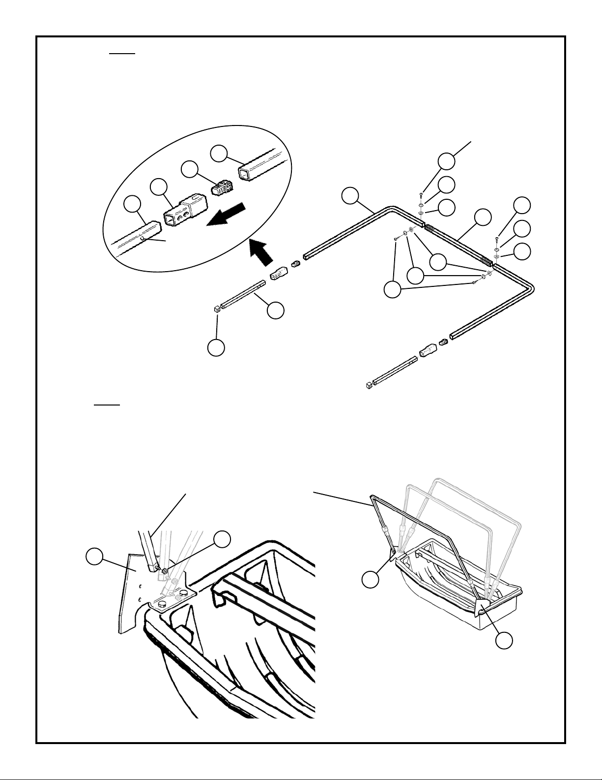
3 1 80172 FrameBracket “A”
4 1 80171 FrameBracket “B”
5 1 80517 Back Wind Support Bar - 49 1/2”
6 1 80518 CenterWind Support Bar - 34 5/8”
7 1 80519 CenterWind Support Bar - 44 3/4”
8 1 80512 AdjustableFront WindSupport Bar
9 2 80470 Main Frame Extension Bar - 31 1/2”
10 2 80471 Main Frame Extension Bar - 32 1/2”
11 4 80472 Main Frame Extension Bar - 30”
12 2 80474 OuterMain FrameBar -33”
13 6 80473 OuterMain FrameBar - 29 9/16”
14 4 80475 MiddleMain FrameBar -52”
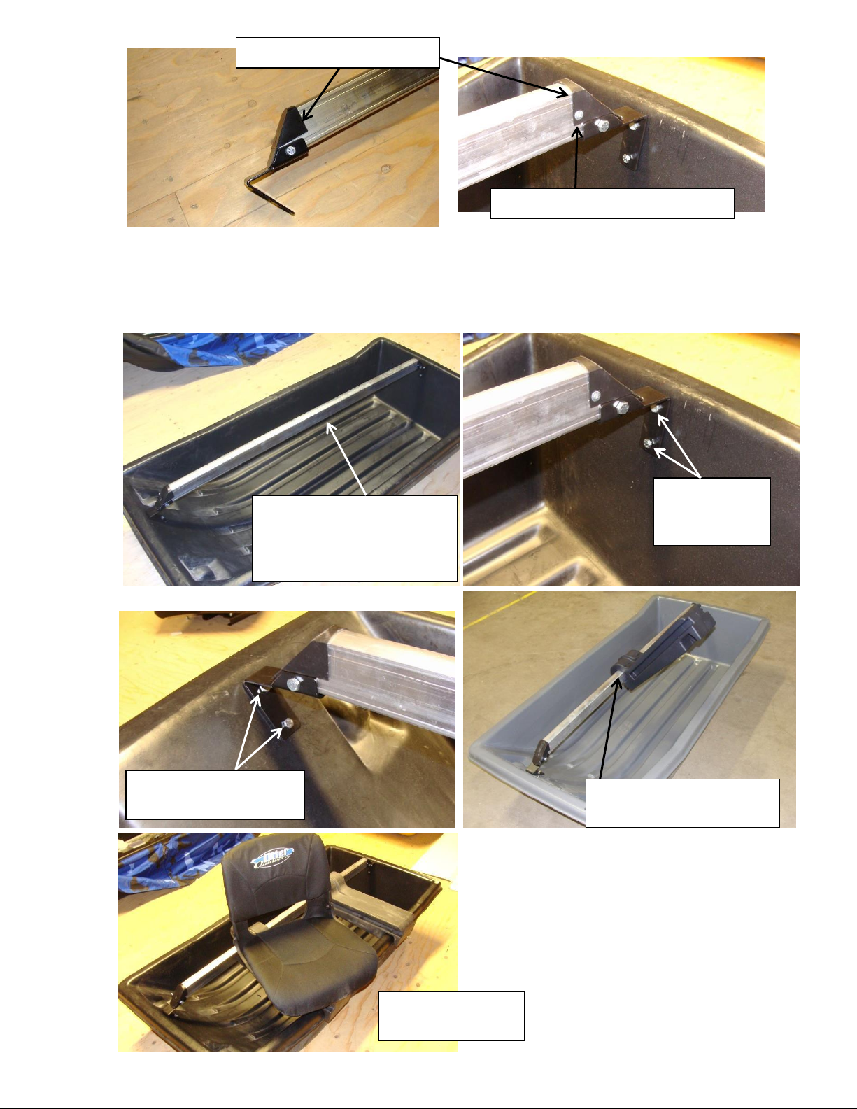
15 2 200861 Seat
16 2 200369 Seat Bracket
17 2 200806 Seat Base
18 1 200379 Seat Rail - 67”
19 2 200196 SeatRail Cap
20 2 200376 Seat Rail Bracket
21 8 200384 Sleeve
22 16 400641 #8 x 3/4” Self Tapping Screw
23 8 200197 Black Plug
24 8 200195 Black End Cap
25 14 200615 5/16Washer
26 8 200944 1/4 x 1/2 Philips Head, Counter Sunk Screw
27 4 401017 1/4 x 3/4 Hex Bolt
28 16 400648 1/4 Nylon Hex Lock Nut
29 2 400367 5/16 x 2 Hex Bolt
30 2 200787 5/16 Nylon Hex Lock Nut
31 8 200235 1/4”Low ProfileNylon LockNut
32 12 200942 3/8”SelfTapping Screw
33 16 200941 Plastic Protector
34 16 200943 Star Washer
35 1 200976 Plastic Trim Lock Kit
MODELNUMBERS:MODELNUMBERS:
MODELNUMBERS:
Complete PkgComplete Pkg
Complete Pkg Pro XT Thermal LodgePro XT Thermal Lodge
Pro XT Thermal LodgePro XT Thermal Lodge
Pro XT Thermal Lodge 200958200958
200958200958
200958 2
1
5
6
7
8
3
11 10
9
13
12
14
4
16 17
15
Front
Back
Center
Bottom
Back &
Center
Front
Bottom All
23
22
21
19
18
20
Instructions - 70761
24 25 282726 3029 31 32 33 34 35
Installing the seating system before assembling the frame and
canvas will make installation easier.
1. Install the seat slide brackets onto the seat swivel using the flathead machine
screws and nylock nuts and washers. Leave the bolts loose enough to
allow them to
be adjusted.
Tools Required:
Ratchet & 7/16” socket
7/16”wrench
Short extension for Ratchet or 7//16” deep socket
Drill/Driver
Phillips Bit
Phillips Screwdriver
½” Wrench
½” socket
5/16” Drill Bit
7/16” Drill Bit
Seat slides
Flathead Phillips bolts are inserted
here
Phillips screwdriver is inserted through
these holes to tighten flathead screws.
Washer and nylock nut
attach on the backside.
2. Slide brackets and swivel part way onto the plastic base. Adjust the fit to be snug by
pressing in on the brackets. However the brackets still need to be able to slide smoothly
back
and forth on the plastic base. Tighten the bolts securely once the fit is correct.
3. Line up the swivel with the inserts in the bottom of the seat. Loosely install the ¼ x ¾”
Phillips head bolt with washers (included in the seat box) into the inserts in the bottom of
the seat. Tighten all 4 bolts securely once the
swivel is properly positioned.
Press in on slide
brackets and adjust
for proper fit on
plastic base.
Tighten all 4 nylock
nuts securely once
properly adjusted.
Install Phillips
head bolts and
washers here.
4. Drill out the four pre-marked holes for the seat rail brackets as shown using a 5/16”
drill bit. The sled may be tipped upside down to make drilling the holes easier.
5. Attach the metal brackets to the seat rail using the 5/16” bolts and nuts. The bracket
with
the greater angle goes toward the front of the sled. Attach plastic end caps onto the
seat
rail using the self tapping screws. A small pilot hole may be drilled to ease
installation.
Drill four pre-marked holes at these
locations.
Drill these 2 pre-marked holes with
a 5/16 drill bit.
Drill these 2 pre-marked holes with
a 5/16 drill bit.
Bracket for front of sled.
Bracket for rear of sled.
6. After the brackets and end caps are installed the seat rail may be bolted into place
with the ¼” bolts, washers and nylock nuts
using the previously drilled holes.
Install plastic base and seat onto the rail. Use WD-40 or silicone to lubricate plastic
seat base opening so it will go onto the aluminum rail easier.
Install plastic end caps here.
Secure with ¾” self tapping screws.
Install seat rail here. Some
downward pressure may be
necessary to get the holes to
align.
Bolt rear
bracket to sled
here.
Bolt front bracket to sled
here.
Lubricate here for easier
pivoting on the seat rail.
Two seat bases and
one seat installed.
Page 5
Diagram8
Item 25 - 5/16 Washer
Item 28 - 1/4 Nylon Hex Lock Nut
10. Bolt frame brackets (Item 3 and Item 4) to sled using holes predrilled in Step 8.
Use appropriate fasteners shown in Diagram 8.
3
25
28
4
7. Position sled (Item 1) as shown in Diagram 7 with curved front to your left.
8. Drill the 4 marked holes using a 5/16” bit.
9. Drill the 7/16” hole in center of lip approximately 16” from bend in sled. The back wind support bar (Item 5 not
shown) is to be propped here. Ref Diagram 7.
Diagram7
Drill4 premarked holes
with 5/16” drill bit.
16”
7/16”
Hole
1
Seatassemblynotshownforclarity.
Page 6
12. Attach Back and Center main frame assemblies (Assembled in Step 11) onto frame brackets (Item 3 and 4).
Secure with 1/4 nylon hex lock nut (Item 28). Ref. Diagram 10.
4
3
3
Back Main FrameAssembly
CenterMain FrameAssembly
28
Diagram10
11. Assemble Back and Center Main Frame Bars: Insert the outer main frame bar (Item 13) into the middle main
frame bar (Item 14). Fasten with self-tapping screw (Item 22), plastic protector (Item 33), and star washer (Item
34). Slide the sleeve (Item 21) over the main frame extension bar (Item 11). (Line up holes with button lock,
press lock in as you slide over the bar). Insert the black plug (Item 23) into the main frame extension bar
(Item 11). Insert outer main frame bar (Item 13) into sleeve (Item 21). Cover end of main frame extension bar
(Item 11) with black end cap (Item 24). Ref. Diagram 9.
Diagram9
23 13
21
24
Button lock
shouldface
inward
11 13
11
Note: Use a light oil
such as WD-40 to
lubricate the poles to help
them slide easier. Wipe
off any excess. Silicone
may be substituted but is
not as effective.
14
33
34
33
34
22
33 34
22
Important: Do
not overtighten to
preventstripping
of threads.
22
Page 7
14. Attach Front main frame assembly (Assembled in Step 13) onto frame brackets (Item 3 and 4). Secure with 1/4
nylon hex lock nut (Item 28). Ref. Diagram 12
4
3
3
FrontMain FrameAssembly
Diagram12
28
13. Assemble Front Main Frame Bar: Insert the outer main frame bar (Item 12) into the middle main frame bar
(Item 14). Fasten with self-tapping screw (Item 22), plastic protector (Item 33), and star washer (Item 34). Slide
the sleeve (Item 21) over the main frame extension bar (Item 10). (Line up holes with button lock, press lock
in as you slide over the bar). Insert the black plug (Item 23) into the main frame extension bar (Item 10). Insert
outer main frame bar (Item 12) into sleeve (Item 21). Cover end of main frame extension bar (Item 10) with black
end cap (Item 24). Ref. Diagram 11.
Diagram11
Note: Use a light oil
such as WD-40 to
lubricate the poles to help
them slide easier. Wipe
off any excess. Silicone
may be substituted but is
not as effective.
23 12
21
24
Button lock
shouldface
inward
10 12
10
14
33
34
33
34
22
33 34
22
Important: Do
not overtighten to
preventstripping
of threads.
22
Page 8
16. Attach Bottom main frame assembly (Assembled in Step 15) onto frame brackets (Item 3 and 4). Secure with
1/4 nylon hex lock nut (Item 28). Ref. Diagram 14.
4
3
3
Diagram14
28
Bottom Main FrameAssembly
23
21
Button lock
shouldface
inward
15. Assemble Bottom Main Frame Bar: Insert the outer main frame bar (Item 13) into the middle main frame bar
(Item 14). Fasten with self-tapping screw (Item 22), plastic protector (Item 33), and star washer (Item 34). Slide
the sleeve (Item 21) over the main frame extension bar (Item 9). (Line up holes with button lock, press lock
in as you slide over the bar). Insert the black plug (Item 23) into the main frame extension bar (Item 9). Insert
outer main frame bar (Item 13) into sleeve (Item 21). Cover end of main frame extension bar (Item 9) with black
end cap (Item 24). Ref. Diagram 13.
Diagram13
24
9
13
9
13
Note: Use a light oil
such as WD-40 to
lubricate the poles to help
them slide easier. Wipe
off any excess. Silicone
may be substituted but is
not as effective.
14
33
34
33
34
22
33 34
22
Important: Do
not overtighten to
preventstripping
of threads.
22
Page 9
18. Install wind support bars starting in back (Item 5), up through center (Item 6), then between the front and center
main frame bars (Item 7) and finally with adjustable wind support bar (Item 8) in front. Ref Diagram 16.
Diagram16
Bottom Main Frame Bar
Front Main Frame Bar
CenterMainFrame Bar
Back Main Frame Bar
5
67
8
17. Set up main frame bars by grasping with both hands and pushing upward until button clicks into place. Start with
bottom main frame bar and continue to the back main frame bar pushing lengthened bars into appropriate position
Ref. Diagram 15.
Diagram15
Bottom Main
Frame Bar
FrontMain
Frame Bar
CenterMain
Frame Bar Back Main
Frame Bar
Note:Note:
Note:Note:
Note: Seat
assembly not
shownfor clarity
Note: There are two
holes that the buttons can
clickinto to optimize the
fit of the canvas.
Page 10
19. Slide the tent over the main frame bar
assembly, then fasten the velcro straps
on the inside of the tent to each main
frame bar. Ref. Diagram 17.
Tent
MainFrame
Assembly
Diagram17
Note: Collapsing
the center and front
main frame poles
part way down
willmakeinstallation
easier.
45° angle
35
45° angle
8”
33”
23”
16”
33”
23”
20. Once the canvas is on the frame and the Velcro attached, extend all of the frame poles upward and make sure all
of the wind poles are installed. Extend the front adjustable wind pole so that the fabric in front is snug and not
sagging. It will be necessary to loosen the back adjustable wind pole to achieve this. Once the front is set and the
top wind poles are in place, the back adjustable wind pole can be extended until it is snug. Install the plastic trim
lock in the positions shown in Diagram 18.
Install the back center trim lock first and work your way around the sled, pulling the fabric snug as you go. The
canvas will be trapped between the sled lip and the trim lock, and will also wrap underneath the sled lip providing a
very good seal. Check the fit of the canvas and adjust as necessary before installing the screws to hold the trim
lock in place.
Attach the six plastic trim locks (Item 35) to the sled in the locations shown with the 45° angled edge to the inside
of the sled. Ref. Diagram 18.
Diagram18
Page 11
GeneralNote:Becarefulwithtentwindowsincoldweather,as creasing orcrushing them will cause
breakage.
Caution: Use adequate ventilation. PortCaution: Use adequate ventilation. Port
Caution: Use adequate ventilation. Portable heaters use up oxygenable heaters use up oxygen
able heaters use up oxygenable heaters use up oxygen
able heaters use up oxygen
and emit carbon monoxide. Use reflectors and identifying lights afterand emit carbon monoxide. Use reflectors and identifying lights after
and emit carbon monoxide. Use reflectors and identifying lights after
dark or during limited visibilitydark or during limited visibility
dark or during limited visibility..
..
.
To Collapse Tent and Transport:
1. Remove support bars and store inside the sled.
2. Retract main frame bars by pressing in button while
sliding the bar farther into the tube.
3. Fold the tent in towards the sled so all the bars are
laying on top of the sled.
4. Tuck in excess tent material.
5. Ready for transport.
6. Reverse to set up the fishhouse again.
Foldtentinward
towardssled.
21. On the front of the fishhouse, start in the corners and work inward, snap the plastic trim seal on the canvas tent
(Item 2) to the lip edge of the sled (Item 1). The tent (Item 2) will meet in the middle and should be free to open
and close so it can be removed.Ref. Diagram 19.
Diagram19
Start here and
work inward
Back
Left Side
Front
RightSide
Start Here and
work inward
2
1
Velcro attaches
at this point
Trim seal
Self-tapping screw
Detail A
22
Left Side
Back
1
Lineupseam
onthe corner
NOTE: Check for proper fit of canvas
before installing screws in trim lock.
Page 12
Otter Pro XT Lodge
October, 2015
Otter Outdoors Inc.
411W Congress St.• Maple Lake,MN 55358
Phone320-963-6480 •www.otteroutdoors.com

Other Otter Tent manuals

Otter Pro X-Over Cottage Manual

Otter

Otter Pro X-Over Cottage Manual

Otter Pro X-Over Lodge Manual

Otter

Otter Pro X-Over Lodge Manual

Otter Pro X-Over Cabin Manual

Otter

Otter Pro X-Over Cabin Manual

Otter XT X-Over Resort Manual

Otter

Otter XT X-Over Resort Manual

Otter Pro XT Cabin Manual

Otter

Otter Pro XT Cabin Manual

Popular Tent manuals by other brands

U-Line H-9236 manual

U-Line

U-Line H-9236 manual

ShelterLogic Peak Style 8' W x 8' H Assembly instructions

ShelterLogic

ShelterLogic Peak Style 8' W x 8' H Assembly instructions

SunnCamp Companion 300 manual

SunnCamp

SunnCamp Companion 300 manual

Dancover 5.4m Series manual

Dancover

Dancover 5.4m Series manual

Euromate 126194 operating instructions

Euromate

Euromate 126194 operating instructions

Eureka Grand-Annex User instructions

Eureka

Eureka Grand-Annex User instructions

Kayoba 008785 operating instructions

Kayoba

Kayoba 008785 operating instructions

Rocktrail POP-UP TENT 2.1 Operation and safety notes

Rocktrail

Rocktrail POP-UP TENT 2.1 Operation and safety notes

Eureka! Tents Titan Assembly instructions

Eureka! Tents

Eureka! Tents Titan Assembly instructions

Kodiak Super-6 2061 owner's manual

Kodiak

Kodiak Super-6 2061 owner's manual

Vango SOUL Pitching instructions

Vango

Vango SOUL Pitching instructions

Clas Ohlson 31-5773 instruction manual

Clas Ohlson

Clas Ohlson 31-5773 instruction manual

Rocktrail Z29748 Assembly and Safety Advice

Rocktrail

Rocktrail Z29748 Assembly and Safety Advice

Boutique Camping INNER TENT instruction manual

Boutique Camping

Boutique Camping INNER TENT instruction manual

Bestway Inflate Your Fun 68044 owner's manual

Bestway

Bestway Inflate Your Fun 68044 owner's manual

TMG TMG-GH2040 product manual

TMG

TMG TMG-GH2040 product manual

Zempire AEROBASE 3 SHELTER Series instructions

Zempire

Zempire AEROBASE 3 SHELTER Series instructions

GigaTent Katahdin FT020 owner's manual

GigaTent

GigaTent Katahdin FT020 owner's manual

manuals.online logo
manuals.online logoBrands
  • About & Mission
  • Contact us
  • Privacy Policy
  • Terms and Conditions

Copyright 2025 Manuals.Online. All Rights Reserved.