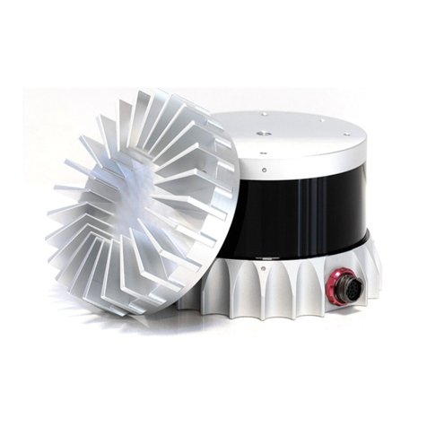
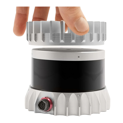
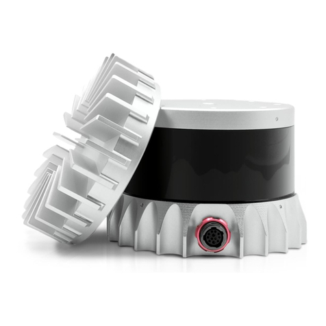
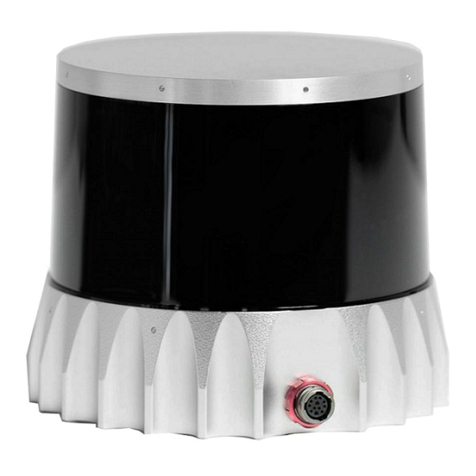
Ouster OS2 Instructions for use

OS2HardwareUserManual
For Rev-05 OS2 Sensors
Ouster
Sep27,2021

Contents
1 Important SafetyInformation 3
1.1 Safety&LegalNotices........................................ 3
1.2 ProperAssembly,Maintenanceand SafeUse . . . . . . . . . . . . . . . . . . . . . . . . . . 6
2 Sensor 7
2.1 Overview................................................ 7
2.2 OS2ProductModels......................................... 7
3 MechanicalInterface 8
3.1 IncludedComponents ........................................ 8
3.2 MountingGuidelines......................................... 9
3.3 OperatingTemperatures....................................... 10
4 ElectricalInterface 10
4.1 PowerSupplyandOperatingVoltage . . . . . . . . . . . . . . . . . . . . . . . . . . . . . . . 10
4.2 ConnectionthroughtheInterfaceBox . . . . . . . . . . . . . . . . . . . . . . . . . . . . . . . 10
4.3 DirectCableConnectionandPinout . . . . . . . . . . . . . . . . . . . . . . . . . . . . . . . . 11
5 DigitalIO 12
5.1 SYNC_PULSE_IN........................................... 12
5.2 MULTIPURPOSE_IO(M_IO).....................................14
6 OS2CADfiles 14
7 Accessories 15
7.1 Cables ................................................. 15
7.2 InterfaceBox.............................................. 17
8 GPS/GNSS SynchronizationGuide 23
8.1 SettingupyourGPS/GNSS.....................................23
8.2 ConnectingtheHardware......................................23
8.3 ConfiguringtheOusterSensor . . . . . . . . . . . . . . . . . . . . . . . . . . . . . . . . . . . 26
9 Support 26
2

1 ImportantSafetyInformation
1.1 Safety&LegalNotices
The OS2-128, OS2-64, and OS2-32 have been evaluated to be Class 1 laser products per 60825-1:
2014 (Ed. 3) and operateinthe865nm band.
L’OS2-128,l’OS2-64,etl’OS2-32répondentauxcritèresdesproduitslaserdeclasse1,selonlanorme
IEC60825-1: 2014(3èmeédition)etémettentdansledomainedel’infrarouge,àunelongueurd’onde
de865nmenviron.
FDA21CFR1040Notice: OS2-128,OS2-64,andOS2-32complywithFDAperformancestandardsfor
laserproductsexceptfor deviationspursuanttoLaserNoticeNo. 56,datedJanuary19,2018.
Notice FDA 21CFR1040: L’OS2-128, l’OS2-64, et l’OS2-32 sont conformes aux exigences de perfor-
mances établies par la FDA pour les produits laser, à l’exception des écarts en application de l’avis
nº56,datédu 19janvier2018.
Figure1.1: Class 1LaserProduct
Figure1.2: Caution “SharpEdges”
Thefollowingsymbolsappearontheproductlabelandintheusermanualhavethefollowingmeaning.
CAUTIONS
3

Figure1.3: Thissymbolindicatesthat thesensoremitslaser radiation.
Figure1.4: This symbolindicatesthepresenceofahotsurfacethat maycauseskinburn.
TheOS2isahermetically sealedunit,andisnonuser-serviceable.
Useofcontrols,oradjustments,orperformanceofproceduresotherthanthosespecifiedherein,
mayresultinhazardousradiationexposure.
Use of the OS2 is subject to the Terms of Sale that you agreed and signed with Ouster or your
distributor/integrator. Included inthesetermsaretheprohibitionsof:
Removingorotherwise openingthesensorhousing
Inspectingtheinternalsofthesensor
Reverse-engineeringanypart ofthesensor
Permittinganythirdpartytodoanyoftheforegoing
Operating the sensor without the attached mount that is shipped with the sensor, or attaching
the sensor to a surface of inappropriate thermal capacity runs the risk of having the sensor
overheatundercertain circumstances.
This product emits Class 1 invisible laser radiation. The entire window is considered to be the
laseraperture. WhileClass1lasersareconsideredtobe“eyesafe”,avoidprolongeddirectview-
ingofthelaserand donotuseopticalinstrumentstoviewthelaser.
Whenoperatedinan ambienttemperature>40�°C, themetallicsurfacesof the sensormay be
hot enough to potentially cause skin burn. Avoid skin contact with the sensor’s base, lid and
the heatsink when the sensor is operated under these conditions. The sensor should not be
used in an ambient temperature above 50°C. The maximum safety certified ambient operating
temperatureis50°C.
PRECAUTIONS:
L’OS2 est une unité hermétiquement scellée, qui ne peut être entretenue ou modifiée par
l’utilisateur.
L’utilisation de commandes, de réglages, ou l’exécution de procédures autres que celles spéci-
fiéesdansleprésentdocumentpeuvententraînerdesrayonnementslaserdangereux.
4

L’utilisation de l’OS2 est soumise aux conditions de vente signées avec Ouster ou le distribu-
teur/intégrateur, incluantl’interdictionde:
Retirerououvrirdequelquefaçonle boîtierducapteur
Analyserlescomposantsinternesducapteur
Pratiquerlarétro-ingénieriedetouteoupartiedu capteur
Autoriserunetiercepersonneà menerlesactionslistéesci-dessus
L’utilisation du capteur sans le support (fourni avec les capteur) ou sans contact avec une sur-
faceayantdescapacitésthermiquesadéquatespeut entraînerunesurchauffedu capteurdans
certainesconditions.
Ce produit émet un rayonnement laser invisible de classe 1. L’ouverture de sortie du laser est
constituéepar lafenêtreducapteurdanssa totalité. Mêmesiles lasersdeclasse1nesont pas
considéréscommedangereuxpourlesyeux,neregardezpasdirectementlerayonnementlaser
defaçonprolongéeetn’utilisezpasd’instrumentsoptiquespourobserverlerayonnementlaser.
Lors d’une utilisation à température ambiante supérieure à 40°C, la surface métallique du cap-
teur peut présenter des risques de brûlures pour la peau. Dans ces conditions, il est important
d’éviter tout contact avec la partie supérieure, la base ou le dissipateur thermique du capteur.
Le capteur ne doit pas être utilisé à une température ambiante supérieure à 50˚C. 50˚C est la
températuremaximalecertifiéed’opérationsûreducapteur.
EquipmentLabel: IncludesmodelandserialnumberandanoticethatstatestheunitisaClass1Laser
Product,is affixed tothe undersideofthe SensorEnclosureBase. It isonly visible aftertheattached
mountwithwhichtheSensorisshipped,isremoved. ForlocationdetailspleaserefertofigureSensor
Components intheMechanicalInterfaceSection.
L’étiquettedel’équipement,comprenantlemodèle,lenumérodesérie,etlaclassificationduproduit
laser (ici, classe 1), est apposée au-dessous de la base du boîtier du capteur. Il n’est visible qu’après
avoir retiré le diffuseur de chaleur avec lequel le capteur est expédié. L’emplacement est décrit avec
précisiondansla sectionSensor Components.
ElectromagneticCompatibility: The OS2isan FCC47 CfR15SubpartB device. This devicecomplies
with part 15 of the FCC Rules. Operation is subject to the following conditions: (1) This device may
not cause harmful interference, and (2) this device must accept any interference received, including
interferencethatmaycauseundesiredoperation.
“Ouster” and “OS2” are both registered trademarks of Ouster, Inc. They may not be used without
expresspermissionfromOuster,Inc.
Ifyouhaveanyquestionsabouttheabovepoints,contact usat[email protected].
5

1.2 ProperAssembly,MaintenanceandSafeUse
TheOS2canbeeasilysetupbyfollowingtheinstructionsoutlinedinMountingGuidelines. Anymount-
ingorientationisacceptable. Eachsensorisshippedwithanattachedmountthatcanbeusedfortest
ornormaluse within thespecifiedoperating conditions. Thesensormay alsobeaffixedto anyother
user specific mount of appropriate thermal capacity. Please contact Ouster for assistance with ap-
provingtheuseofuserspecificmountingarrangements.
Any attempt to utilize the sensor outside the environmental parameters delineated in the OS2
datasheetmayresultinvoidingofthe warranty.
When power is applied, the sensor powers up and commences boot-up with the laser disabled. The
boot-upsequenceisapproximately60sinduration,afterwhichtheinternalsensoropticssubassem-
blycommencesspinning,thelaserisactivated,andtheunitoperatesinthedefault1024x10Hzmode.
Whenthe sensoris running,and thelaser isoperating,afaintredflickeringlight maybeseenbehind
theopticalwindow.
NotethattheOS2utilizesan865nminfraredlaserthatisonlydimlydiscernibletothenakedeye. The
sensor is fully Class 1 eye safe, though Ouster strongly recommends against peering into the optical
window at close range while the sensor is operating. Ouster sensors are equipped with a multi-layer
seriesofinternalsafetyinterlocks toensurecompliancetoClass1Laser EyeSafelimits.
TheOS2isahermeticallysealedunit,andisnotuser-serviceable. Anyattempttounsealtheenclosure
hasthepotentialtoexposetheoperatortohazardouslaserradiation.
The sensor user interface may be used to configure the sensor to a number of combinations of scan
rates and resolutions other than the default values of 1024 x 10 Hz resolution. In all available combi-
nations,the unithas beenevaluated byanNRTLtoremainwithintheclassificationof aClass 1Laser
Deviceasper IEC60825-1:2014(Ed. 3).
Assemblagecorrectetutilisationsûre
L’OS2s’installefacilementen fixantla basesur unsupportpercédetrousconcordants,et ensuivant
les instructions d’interconnexion décrites dans la section Mounting Guidelines. Toute orientation de
montage est acceptable. Chaque capteur est expédié équipé d’un dissipateur de chaleur, utilisable
en phase de test et en conditions normales. Néanmoins tout autre support présentant une capacité
thermiqueappropriéepourl’applicationdel’utilisateurpeutêtreutilisé. VeuillezcontacterOusterdans
lecasoùunmontage spécifiqueàvotre applicationseraitnécessaire.
Toute tentative d’utilisation du capteur en dehors des paramètres environnementaux définis dans la
fichetechniquede l’OS2 peutentraînerl’annulationdelagarantie.
Lorsquelecapteurestsoustension,celui-cidémarreetcommencesoninitialisationaveclelaserdés-
activé. Letempsdedémarrageestd’environ60s,aprèsquoilesous-systèmeoptiqueentreenrotation
etlelaserestactivé,lecapteuropèrealorsdanssonmodepardéfautde1024x10Hz. Lorsquelecap-
teur est en marche et que le laser est activé, on peut apercevoir une faible lumière rouge vacillante
derrièrelavitreteintée. L’OS2utiliseunelongueurd’ondesinfra-rougede865nmnmàpeinepercep-
tible pour l’œil humain, et le rayonnement laser IR émis est sans danger pour les yeux. Cependant,
bienquelesrayonnementslaserdeclasse1soientsansdangerdansdesconditionsraisonnablement
prévisibles,Ousterrecommandefortementdenepasregarderfixementlavitreteintéependantquele
6
capteurestenmarche. L’OS2estuneunitéhermétiquementscellée,quinepeutpasêtreentretenue,
modifiée ou réparée par l’utilisateur. Toute tentative d’ouverture du boîtier a pour risque d’exposer
l’opérateuràunrayonnementlaserdangereux.
L’OS2 est une unité hermétiquement scellée, qui ne peut pas être entretenue, modifiée ou réparée.
Toutetentatived’ouvertureduboîtierapourrisqued’exposerl’opérateuràunrayonnementlaserdan-
gereux.
LescapteursOustersontéquipésd’unesériededispositifsdesécuritéàplusieursniveaux,defaçonà
assurerentoutescirconstanceslerespectdeslimitesd’irradiancecorrespondantaux rayonnements
lasersdeclasse 1,sansdangerpourlesyeux.
L’interfaceutilisateurdulogicielducapteurpeutêtreutiliséepourconfigurerlecapteurselonuncer-
tainnombredecombinaisonsdevitessesdebalayageetderésolutionsautresquelesvaleursutilisées
pardéfaut,respectivementde1024x10Hz.
2 Sensor
2.1 Overview
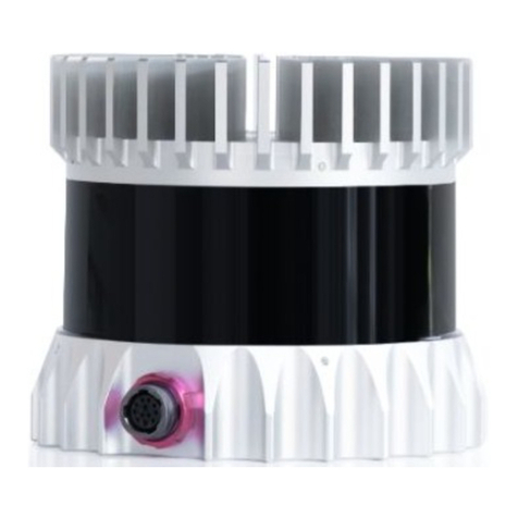
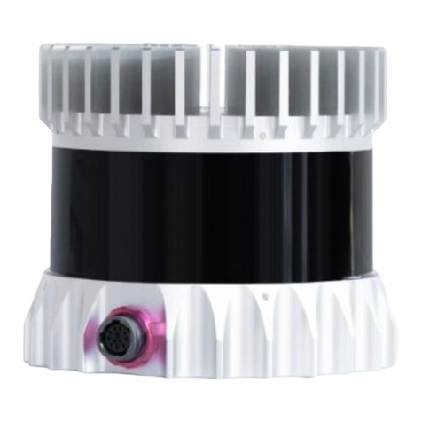
The OS2 offers an industry-leading combination of price, performance, reliability, size, weight, and
power. Itisdesignedforindoor/outdoorall-weatherenvironmentsanda longoperatinglifetime.
The OS2 family of sensors consist of three models, the OS2-128, OS2-64, and OS2-32, with differing
verticalresolution,but identicalmechanicaldimensions.
For the purposes of this document, the term “OS2” refers to the family of sensors, and only where
thereisa differenceinperformancewilleachmodelbe referredtobyitsspecificmodeldesignation.
ThecontentsofthismanualareapplicableonlytoRev05sensors. Pleasecontactsupport@ouster.io
withthesensor serial numbertofind out yoursensor Revinformation. Forallother sensor hardware
revisions,pleaserefertotherespectivehardwareusermanual foundhereHere.
2.2 OS2ProductModels
TheOS2isavailablewith128,64,or32beamsofverticalresolutionandwithUniform,Gradient,Above
Horizon,orBelowHorizonbeam spacingoptions. Productspecs andmoreinformationon thesecon-
figurationscanbe foundontheOS2 productpage.
7

3 MechanicalInterface
3.1 IncludedComponents
TheOS2isshippedwiththefollowingitems:
OS2-128,OS2-64,orOS2-32
Sensortointerfaceboxcable/connector
InterfaceBoxand 24VAC/DCpowersupply(2meters)
RJ45cable(1meter)
BaseplateMount
Figure3.1: SensorComponents
DownloadableCADfiles fortheOS2can befoundonlineat OusterDownloadPage
Warning: ThewateringressprotectionratingforthesensorisonlyvalidiftheI/Ocableisplugged
into the panel mount connector on the base of the sensor, and the locking collet rotated past the
détente click to the properly locked condition i.e past the détente position. The cable and plug
arean elementofthe sensoringressprotectionsystem. Withoutthe connectedcablethe ingress
8

protection rating may be compromised. Bending the cable at a sharp angle directly after egress
fromtheplug overmoldshouldalso beavoided. Sharpbendsandhighaxialstressesonthecable
immediatelyadjacenttotheplugovermoldmaycreateamoistureingresspathintotheconnector.
Pleasenotethe cableminimumbendradiusrequirementsbelow:
3.2 MountingGuidelines
Our sensors ship with modular mounting options. The sensor can be mounted in any orientation.
Propermountingwillensureoptimalsensorperformance,reducingnoisefromvibrationandproviding
efficientheat dissipation.
Mount to a material with high thermal conductivity. The following are recommended aluminum
alloysandtheir thermalconductivity:
1) 6061: 167W/m-K
2) 7075: 130W/m-K
3) 2024: 121W/m-K
Ensureinterfacesareclean andfreefromdebris.
M3 screws are recommended for mounting the sensor. The screw hole pattern in presented in
theSensordrawingaboveSensor Components.
Torque bolts appropriately for the mount material and bolts. A torque of 146cNm is recom-
mendedfora2stainlesssteelscrews.
UseTIM(ThermalInterfaceMaterial)foranyirregularorunmachinedsurfaces.
Donotoverconstrainthesensorifmountingtoboth thetopand thebottom.
Useathermallyconductivepadtoensuregoodconductivitywhilenotoverconstraining.
Ensure your implementation maintains the base and top of the sensor at no greater than 25ºC
aboveambientwithanambientlessthan50ºC.
Theshapeofanyheatsinkshouldmaximizethesurfaceareaforfreeandforcedconvectionwhile
beingthickenoughtoallowtheheattoconductthroughthematerial.
If you have questions about your specific mounting situation please contact the Ouster at sup-
9

3.3 OperatingTemperatures
Thermal requirements specific to Rev 05 are listed below. The sensor has three operating states in
order to manage high temperatures: Active, Shot Limiting, or Inactive. In the standard Active state
the sensor will perform to the range and precision specifications of the datasheet. When the sensor
reachesacertaintemperature(seetablebelowforreference),itentersShotLimitingstateandissues
analert. InShotLimitingstate,thesensor reducespowertothelasersinordertoreducethethermal
load. While in this state, sensor range and precision may degrade by up to 20%. When the sensor
reaches the maximum operating temperature specified below, the sensor may become Inactive and
shutoff.
Table 3.1: MaximumthermalperformanceforRev05OS2Sensor
Convective Air Temp with Radial
HeatsinkandStandardBase
Maxtempbefore shot limiting 55ºC
Tempthatshotlimitingsaturated(sensormayturn
offabovethistemperature) 61ºC
4 ElectricalInterface
4.1 PowerSupplyandOperatingVoltage
The OS2 Rev 05 Sensors are meant to operate at 12V and 24V nominal input voltage. A low voltage
warningwillbetriggeredifthevoltageatthesensorconnectordropsbelow9.5V.Thesensorwillshut
down if this input voltage drops to 9V. The maximum input voltage is 34V for the OS2 sensor. When
usedwithouttheprovidedinterfacebox,ensurethatthepowersupplyiscompliantwiththeoperating
voltagespecifiedaboveandallowstosupply atleast20W.
4.2 ConnectionthroughtheInterfaceBox
The Interface Box that accompanies the OS2 is designed to allow the sensor to be operated for test
andevaluationpurposesinindoor environmentsonly. Itcan be connectedto thesensor with acable
equipped with connectors on both ends. It allows the sensor to be powered up and provides access
to the sensor gigabit Ethernet Interface via a standard RJ45 connector. DC Power to the sensor is
providedtotheInterfaceBox bytheaccompanying24VDCpowersupply.
10

4.3 DirectCableConnectionandPinout
The OS2 can be operated without the use of an Interface Box. In this case, a “pigtail” cable should
beusedandwiresshouldbeconnectedbytheuserfollowingthePinoutpresentedbelow. Whenused
withdirectcableconnection,thesensorshouldstillbeoperatedwithintheoperatingvoltagespecified
insection:ref: ‘PowerSupplyandOperatingVoltage’
Warning: Ousterisnot responsiblefor anyerrorsinwiring as aresultof bypassingthe Interface
Box and this activity may result in a voiding your warranty if it results in damage to the sensor.
The following guidelines for direct cable connection assume use of the Ouster-provided 24V 1.5A
powersupply. Oustercannotbe heldresponsiblefordamagetothedeviceifalternateisused.
Figure4.1: cablepinoutof on-sensorreceptacle
Table4.1: Cablepinoutwires
NetName PinNumber Wire TwistedWith
MULTIPURPOSE_IO 3 Purple,26AWG N/A
SYNC_PULSE_IN 2 Yellow, 26AWG N/A
VCC_24 1 Red,22AWG N/A
GROUND 7 Black,22AWG N/A
TRP_1_P(Ethernet) 5 White/Orange,26AWG Orange
TRP_1_N(Ethernet) 4 Orange,26AWG White/Orange
TRP_2_P(Ethernet) 8 White/Green,26AWG Green
TRP_2_N(Ethernet) 6 Green,26AWG White/Green
TRP_3_P(Ethernet) 9 Blue,26 AWG White/Blue
TRP_3_N(Ethernet) 10 White/Blue,26AWG Blue
continuesonnextpage
11

Table 4.1 –continuedfrompreviouspage
NetName PinNumber Wire TwistedWith
TRP_4_P(Ethernet) 12 White/Brown,26AWG Brown
TRP_4_N(Ethernet) 11 Brown,26AWG White/Brown
5 DigitalIO
5.1 SYNC_PULSE_IN
SYNC_PULSE_IN isadedicatedinputchannelthatisaccessiblewithintheInterfaceBoxJumperJ4. This
channel expects an input pulse sequence which can be used for time synchronization. Refer to the
Software User Manual for more information on configuring this input. Any references to pulse polar-
ity in this document references the signal polarity on the SYNC_PULSE_IN pin of the sensor. This input
channelisprotectedbyan opto-isolatorwhichwilldraw5mAat fulloperation.
Table5.1: SYNC_PULSE_INInterfaceRequirements
Parameter MinVoltage MaxVoltage Min Driver Current
LOGICLOW -30 V 2V N/A
LOGICHIGH 2.9V 30V 3mA @3.3V~5V, 5mA
at24Vandhigher
SYNC_PULSE_IN Interface requirements were tested with 2 m cable Interface Box connection at 2
MHz.
When GPIO has 5 mA drive strength minimum, GPIO can be directly connected to the
SYNC_PULSE_IN pinoftheInterfaceBoxheader. Thisisthemostcommoncaseandhasbeentested
to work on common Arduino microcontroller series. Typical common logic levels of 3.3 V, 5 V
GPIOofmicrocontrollerscanproducedrivestrengthof5mAmin(Arduino,MSP430,etc.).
If the 5 mA drive strength minimum cannot be met, a buffer circuit is required to drive
SYNC_PULSE_IN.Examplecircuitsareprovidedforcommon3.3Vand 5Vlogic.
12

Figure5.1: ExampleCircuits for3.3Vand 5Vlogic
13

5.2 MULTIPURPOSE_IO(M_IO)
MULTIPURPOSE_IO (M_IO) is a configurable input or output channel accessible within the Interface Box
JumperJ4connectedtotheMULTIPURPOSE_IOpinoftheInterfaceBox. Detailedinformationonhow
toconfigurethischannelusingthesensorTCPinterfacecanbefoundintheAPIGuide. Bydefaultthis
channelisdisabled.
WhenthischannelisconfiguredasanOUTPUT,theM_IO sendsapulsesequencethatcanbeusedfor
timesynchronizationoreventtriggeringoutsidethesensor. Forafulldescriptionofoutputpulsetrig-
geringoptions,refertotheSoftwareUserManualformoreinformation. Thisoutputisanopto-isolated
opencollectorcircuit,relyingonanexternallyprovidedpull-upresistor. Thisresistorisprovidedfora
typical3.3V/5Vapplicationas partof theInterfaceBox circuitry.
Table5.2: MULTIPURPOSE_IO -OUTPUTInterfaceRequirements
Parameter Min Max
PullUpVoltage 3.3V 24V
SinkingCurrent N/A 25mA
When this channel is configured as an INPUT, the M_IO can accept a standard NMEA $GPRMC UART
message. These messages are a common way for GPS systems to share timestamp information in
UTC time format. More information on this packet structure and supported baud rates can be found
intheTimeSynchronizationsectionoftheSoftwareUserManual.
Table5.3: MULTIPURPOSE_IO-INPUTInterfaceRequirements
Parameter MinVoltage MaxVoltage Min Driver Current
LOGICLOW -30 V 2V N/A
LOGICHIGH 2.9V 30V 3mA @3.3V~5V, 5mA
at24Vandhigher
Above are tested with 35m (200uH inductance) cable Interface Box connection at 115200 Baudrate.
6 OS2CADfiles
Themostup-to-dateCADfilesofall ourproductscanbe foundonourLidar ProductDetailspage.
14

7 Accessories
7.1 Cables
CableTypes
3 types of cables are compatible with the OS2 sensors. Their physical characteristics are presented
inthetableCable Characteristics.
Thecable andplugareanelementofthesensoringressprotection. Withoutthis,theingressprotec-
tion rating may be compromised. Bending the cable at a sharp angle directly after egress from the
plugovermoldshouldalsobeavoided. Sharpbendsandhighaxialstressesonthecableimmediately
adjacent to the plug over mold may create a moisture ingress path into the connection. Please note
thecableminimumbendradiusrequirements.
Note: We nolonger offerType1 cablesforsale. Please contactyour Oustersalesrepresentativefor
questionsregardingavailablecablelengths, connectortypes,andterminationoptions.
Table 7.1: Cable Characteristics
Cable Outer Diame-
ter Cable Minimum Bend
(Static) Cable Minimum Bend (Flexi-
ble)
Type 1
(Thick) 10.5mm 79mm 158mm
Type2(Thin) 8mm 40mm 80mm
Type3 8.2mm 41mm 82mm
Note: Type 3 Cable has an imprint that states “Type 3” on it whereas, Type 2 does not have any
identifiers.
15

ElectricalCharacteristics
Ouster has characterized the cable resistance and contact resistance of our cables at room temper-
ature. Thiscanbe foundbelow:
Table 7.2: ElectricalCharacteristics
Cable Maximum Cable Re-
sistance(Ω/m) Typical End to End Resis-
tancefor5mCable(Ω) AdmissibleNominalOper-
atingvoltage(V)
Type 1
(Thick) 0.110 0.45 24
Type 2
(Thin) 0.110 0.45 24
Type3 0.042 0.3 12/24
For full sensor functionality, a minimum of 9.5 V must reach the sensor. To compensate for losses
through wire resistance, a higher voltage must be provided to the interface end of the cable, which
maybe the InterfaceBoxor the pigtailwires. Ifthe sensor isbelowthis voltagefor atleast1 second,
theINPUT_VOLTAGE_LOWerrorwill betriggered.
Thefollowinggraph can beusedas a guide todetermine theappropriate inputvoltagetothesensor
connectorforyourdesiredcablelength. Thevaluesonthegraphwerecalculatedusingidealizedcable
resistancesderivedfromtheAWGsystemandassumed maximumpowerdrawfromthesensor.
16

7.2 InterfaceBox
The Ouster Interface Box is a support tool for use in laboratory environments to assist customers in
evaluating Ouster’s LiDAR sensor products and in the development of software. The Interface Box is
notprotectedfromingressofmoistureorsolidparticlesand isnotintendedforuseoutdoors.
Figure7.1: InterfaceBoxRev05
Interfaces
AllInterfaceBoxes areprovidedwithaDCpowerportandan8-pin modularjackforEthernet.
Interface Boxes provided with Type 1 and Type 2 cables are assembled with integral cables for con-
nectiontoOuster’ssensors. Thiscablecannotbedisconnectedfromtheinterfacebox, asthereisno
connectoravailable.
The Interface Boxes with Type 3 cables are provided with an output connector and a separate con-
nectorizedcableforconnectiontoOuster’ssensors. TheseInterfaceBoxesalsohaveanewGPSinput
connector capable of accepting operating TTL levels originating in a separate GPS device contain-
ing static electricity dissipation circuitry. Example: GPS Module compatible with Ouster Sensor GPS
Module.
Note: If you need support to configure the GPS to works with our sensor please contact sup-
17

Warning: RISK OF FIRE OR ELECTRIC SHOCK. DO NOT CONNECT THE GPS CONNECTOR DI-
RECTLYTOANANTENNA.
Components
Figure7.2: InterfaceBoxSpecification
1-Sensorconnector. Connecttothesensorwithadouble-ended connectorcable.
2-Ethernetjack. RJ45,gigabitspeed(1000base-T).
3-VINBarrelJack. Usewitha2.5mminnerdiameter,5.5mmouterdiameterbarrelplug.
4-Userreplaceable5Afuse. UseonlyLittlefuse#0891005.
5 - VIN green LED indicator (D2), fuse-protected VIN header (J10) and Ground header / jumper
storage(J14).
6-OnboardMAXM15067buckpoweringVCC_3P3|5. VCC_3P3|5suppliestheonboardLEDsand
pullups,andisuseraccessibleviaheadersJ2&J7. HeaderJ5isusedtoselectthebuck’soutput
voltage: installajumperfor3.3V,leaveopenfor5V.WARNINGS:Maxallowableuserconsumption
is210mA.EnsurepowertotheInterfaceBoxisdisconnectedwhenchangingbuckoutputvoltage
viaJ5.
7 - 3.3kΩ pullups to VCC_3P3|5 and green LED indicators for MULTIPURPOSE_IO and
SYNC_PULSE_IN.Installajumperontherespectiveheader(J8orJ9)toenablethe pullup.
18

Figure7.3: J8&J9Circuitry
8 - 0.1” pitch, 4x2 pin header J7. GPS_TX (Pin 1) is only connected to connector J2; it is not
connectedtothesensor.
Figure7.4: J7Circuitry
9 - 6-pin JST SH/SR connector J2. VCC_J2 (Pin 2) is connected to VCC_3P3|5 by installing a
jumperon header J6. GPS_TX(Pin 6)is onlyconnected toheader J7;itis notconnected tothe
sensor.
Connectors
ConnectivityGuide:
RJ45: Ethernetconnectiontoacomputer
6-PINJSTSH/SR:GPS connectorport
BarrelJack: 24VDCpowersupply
19

Figure7.5: J2Circuitry
Figure7.6: ConnectorOutline
20
Other manuals for OS2
1
This manual suits for next models
3
Table of contents
Other Ouster Accessories manuals

Ouster
Ouster OS-1-16 Safety guide

Ouster
Ouster OS2 Instructions for use

Ouster
Ouster OS1-128 Instructions for use

Ouster
Ouster OS-1-64 Installation manual

Ouster
Ouster OS0 Instructions for use

Ouster
Ouster OS0-128 Instructions for use

Ouster
Ouster OS0 Instructions for use

Ouster
Ouster OS1 Instructions for use