Ouster OS2 Instructions for use

OS2HardwareUserManual
For Rev C OS2 Sensors
Ouster
Dec01,2020

Contents
1 SafetyandSafeUse 3
1.1 Safety&LegalNotices........................................ 3
1.2 ProperAssembly,MaintenanceandSafeUse . . . . . . . . . . . . . . . . . . . . . . . . . . 5
2 OS2Overview 7
3 OS2ProductModels 8
4 MechanicalInterface 9
4.1 IncludedComponents ........................................ 9
4.2MountingGuidelines......................................... 10
4.3ThermalRequirements........................................ 11
5 ElectricalInterface 12
5.1 InterfaceBox.............................................. 12
5.2 DirectCableConnection andPinout . . . . . . . . . . . . . . . . . . . . . . . . . . . . . . . . 13
6 DigitalIO 14
6.1 SYNC_PULSE_IN........................................... 14
6.2 MULTIPURPOSE_IO(M_IO)..................................... 15
7 OS2CADfiles 17
2

1 SafetyandSafeUse
1.1 Safety&LegalNotices
The OS2-128, OS2-64, and OS2-32 have been evaluated to be Class 1 laser products per 60825-1:
2014 (Ed. 3) and operateinthe 865nmband.
L’OS2-128,l’OS2-64,etl’OS2-32répondentauxcritèresdesproduitslaserdeclasse1,selonlanorme
IEC60825-1: 2014(3èmeédition)etémettentdansledomainedel’infrarouge,àunelongueurd’onde
de865nm environ.
FDA21CFR1040Notice: OS2-128,OS2-64,andOS2-32complywithFDAperformancestandardsfor
laserproductsexcept fordeviationspursuant toLaserNotice No. 56, datedJanuary 19,2018.
Notice FDA 21CFR1040: L’OS2-128, l’OS2-64, et l’OS2-32 sont conformes aux exigences de perfor-
mances établies par la FDA pour les produits laser, à l’exception des écarts en application de l’avis
nº56,datédu 19janvier2018.
Thefollowingsymbolsappearontheproductlabelandinthemanualandhavethefollowingmeaning.
Thissymbol indicatesthatthe sensoremitslaser radiation.
Thissymbol indicatesthepresenceof ahot surfacethat maycauseskin burn.
CAUTIONS:
TheOS2 isahermetically sealedunit, andis nonuser-serviceable.
Useofcontrols,oradjustments,orperformanceofproceduresotherthanthosespecifiedherein,
mayresultin hazardousradiationexposure.
3

Youruseofthe OS2issubjecttothe Termsof Salethatyousignedwith Ousteror yourdistribu-
tor/integrator. Includedinthese termsisthe prohibitionon:
Removingorotherwise openingthe sensorhousing
Inspectingthe internalsofthe sensor
Reverse-engineeringanypart ofthe sensor
Permittinganythirdpartytodoanyof theforegoing
Operating the sensor without either the attached mount with which the sensor is shipped, or
attaching the sensor to a surface of appropriate thermal capacity runs the risk of having the
sensoroverheatunder certaincircumstances.
This product emits Class 1 invisible laser radiation. The entire window is considered to be the
laseraperture. WhileClass1lasersareconsideredtobe“eyesafe”,avoidprolongeddirectview-
ingof thelaserand donot useoptical instrumentstoviewthelaser.
When operated in an ambient temperature >40�°C, the metallic surfaces of the sensor may be
hot enough to potentially cause skin burn. Avoid skin contact with the sensor’s base, lid and
heatsinkwhenthe sensoris operatedunder theseconditions.
PRECAUTIONS:
L’OS2 est une unité hermétiquement scellée, qui ne peut être entretenue ou modifiée par
l’utilisateur.
L’utilisation de commandes, de réglages, ou l’exécution de procédures autres que celles spéci-
fiéesdans leprésentdocument peuvententraînerdesrayonnementslaserdangereux.
L’utilisation de l’OS2 est soumise aux conditions de vente signées avec Ouster ou le distribu-
teur/intégrateur,incluantl’interdictionde:
Retirerououvrir dequelquefaçon le boîtierdu capteur
Analyserlescomposants internesducapteur
Pratiquerlarétro-ingénieriede touteoupartie ducapteur
Autoriserunetiercepersonneà menerles actionslistéesci-dessus
Ce produit émet un rayonnement laser invisible de classe 1. L’ouverture de sortie du laser est
constituéepar lafenêtredu capteurdans satotalité. Mêmesi leslasers declasse 1ne sontpas
considéréscommedangereux pourles yeux, neregardezpasdirectementle rayonnementlaser
defaçonprolongéeetn’utilisezpasd’instrumentsoptiquespourobserverlerayonnementlaser.
Lors d’une utilisation à température ambiante supérieure à 40°C, la surface métallique du cap-
teur peut présenter des risques de brûlures pour la peau. Dans ces conditions, il est important
d’évitertoutcontactaveclapartiesuperieure,labase oule dissipateurthermiquedu capteur.
EquipmentLabel: Notethattheequipmentlabel,whichincludesmodelandserialnumberandnotice
thattheunitisaClass1LaserProduct,isaffixedtotheundersideoftheSensorEnclosureBaseitself.
It is only visible after the attached mount with which the Sensor is shipped, is removed. Please refer
4

tolocationdetails inthe Mechanical Interface section.
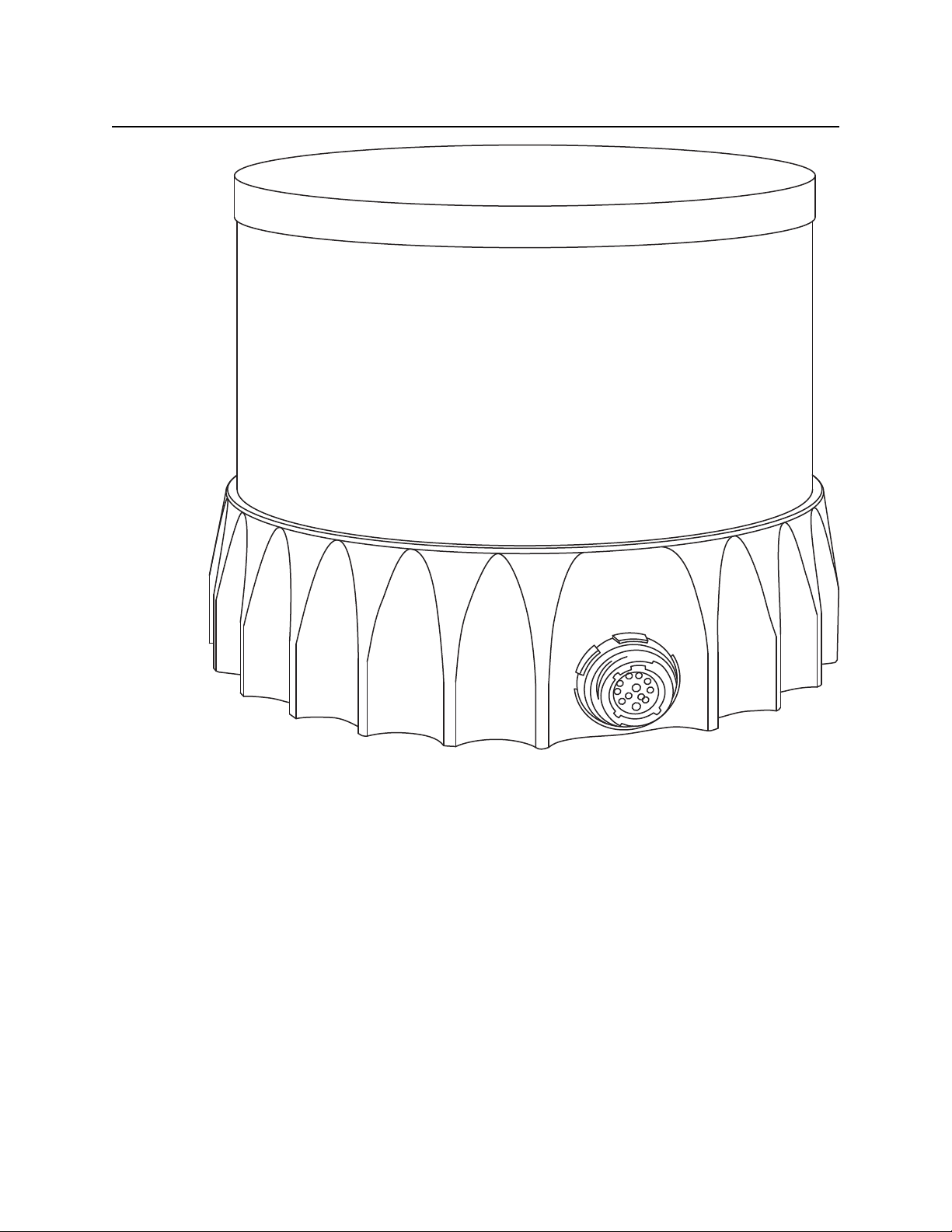
L’étiquettedel’équipement,comprenantlemodèle,lenumérodesérie,etlaclassificationduproduit
laser (ici, classe 1), est apposée au dessous de la base du boîtier du capteur. Il n’est visible qu’après
avoir retiré le diffuseur de chaleur avec lequel le capteur est expédié. L’emplacement est décrit avec
précisiondansla section«Mechanical Interface».
Electromagnetic Compatibility: The OS2 is an FCC 47 CfR 15 Subpart B device. This device complies
with part 15 of the FCC Rules. Operation is subject to the following conditions: (1) This device may
not cause harmful interference, and (2) this device must accept any interference received, including
interferencethatmaycause undesired operation.
“Ouster” and “OS2” are both registered trademarks of Ouster, Inc. They may not be used without
expresspermissionfrom Ouster, Inc.
Ifyouhaveanyquestions abouttheabovepoints,contact usat legal@ouster.io.
1.2 ProperAssembly, Maintenanceand SafeUse
The OS2 may be easily setup by mounting to the base to a mounting with the correct mounting hole
pattern,andfollowingtheinterconnectioninstructionsdelineatedinMountingGuidelines. Anymount-
ing orientation is acceptable. Each sensor is shipped attached to a mount for test or normal use
specified operating temperature range, but the sensor may be mounted directly to any appropriate
mount with Thermal Capacity appropriate for the application of the user. Please contact Ouster for
assistancewith approvingtheuseof userspecific mountingarrangements.
Any attempt to utilize the sensor outside the Environmental parameters delineated in the OS2 data
sheetmayresult invoidingof the warranty.
When power is applied, the sensor powers up and commences boot-up with the laser disabled. The
bootup sequence is approximately 60s in duration, after which the internal sensor optics subassem-
bly commences spinning, and the laser is activated, and the unit operates in the default 1024 x 10
Hz mode. When the sensor is running, and the laser is operating, a faint red flickering light may be
seenbehindthe opticalwindow. NotethattheOS2 utilizesan865nminfraredlaserthat isonlydimly
discernabletothenakedeye,whiletransmittingalasereye-safefundamentalsignalinthe865nmIR
band. WhilethesensorisfullyClass1eyesafe,Ousterstronglyrecommendsagainstpeeringintothe
opticalwindowatcloserangewhilethesensorisoperating. TheOS2isahermeticallysealedunit,and
isnotuser-serviceable. Anyattempttounsealtheenclosurehasthepotentialtoexposetheoperator
tohazardouslaser radiation.
Ouster sensors are equipped with a multi-layer series of internal safety interlocks to ensure compli-
ancetoClass 1Laser EyeSafelimits.
TheSensoruserinterfacemaybeusedconfigurethesensortoanumberofcombinationsofscanrates
andresolutionsotherthanthedefaultvaluesof1024x10Hzresolution. Inallavailablecombinations,
the unit has been evaluated by an NRTL to remain within the classification of a Class 1 Laser Device
asper IEC60825-1:2014(Ed. 3).
5

Assemblagecorrectetutilisationsûre
L’OS2s’installefacilementen fixant la base surun supportpercé detrous concordants,et ensuivant
les instructions d’interconnexion décrites dans la section «Mounting Guidelines». Toute orientation
demontageestacceptable. Chaquecapteurestexpédiééquipéd’undissipateurdechaleur,utilisable
en phase de test et en conditions normales. Néanmoins tout autre support présentant une capacité
thermiqueappropriéepourl’applicationdel’utilisateurpeutêtreutilisé. VeuillezcontacterOusterdans
lecas oùunmontage spécifiqueà votreapplicationseraitnécessaire.
Toute tentative d’utilisation du capteur en dehors des paramètres environnementaux définis dans la
fichetechniquede l’OS2peut entraînerl’annulationde lagarantie.
Lorsquelecapteurestsoustension,celui-cidémarreetcommencesoninitialisationaveclelaserdés-
activé. Letempsdedémarrageestd’environ60s,aprèsquoilesous-systèmeoptiqueentreenrotation
etlelaserestactivé,lecapteuropèrealorsdanssonmodepardéfautde1024x10Hz. Lorsquelecap-
teur est en marche et que le laser est active, on peut apercevoir une faible lumière rouge vacillante
derrièrelavitreteintée. L’OS2utiliseune longueurd’ondesinfra-rougede865nmnm àpeinepercep-
tible pour l’œil humain, et le rayonnement laser IR émis est sans danger pour les yeux. Cependant,
bienquelesrayonnementslaserdeclasse1soientsansdangerdansdesconditionsraisonnablement
prévisibles,Ousterrecommandefortementdenepasregarderfixementlavitreteintéependantquele
capteurestenmarche. L’OS2estuneunitéhermétiquementscellée,quine peutpasêtreentretenue,
modifiée ou réparéepar l’utilisateur. Toute tentative d’ouverture du boîtier a pour risque d’exposer
l’opérateuràun rayonnementlaser dangereux.
L’OS2 est une unité hermétiquement scellée, qui ne peut pas être entretenue, modifiée ou réparée.
Toutetentatived’ouvertureduboîtierapourrisqued’exposerl’opérateuràunrayonnementlaserdan-
gereux.
LescapteursOustersontéquipésd’unesériededispositifsdesécuritéàplusieursniveaux,defaçonà
assureren toutescirconstances lerespectdes limitesd’irradiancecorrespondantaux rayonnements
lasersdeclasse 1,sans dangerpourles yeux.
L’interfaceutilisateurdulogiciel ducapteurpeutêtreutiliséepour configurerle capteurselonuncer-
tainnombredecombinaisonsdevitessesdebalayageetderésolutionsautresquelesvaleursutilisées
pardéfaut,respectivementde 1024x10 Hz.
6

2 OS2Overview
The OS2 offers an industry-leading combination of range, resolution, price, performance, reliability,
size, weight, and power. It is designed for indoor/outdoor all-weather environments. As the smallest
and lightest long-range high-resolution lidar on the market, the OS2 can be directly integrated into
vehicles,robots,anddrones.
The OS2 family of sensors consist of three models, the OS2-128, OS2-64, and OS2-32, with differing
resolution,butof identicalmechanical dimensions.
HIGHLIGHTS
Fixedresolutionper frameoperatingmode
Camera-gradeintensity, near-infrared,andrangedata
Multi-sensorcrosstalkimmunity
Simultaneousand co-calibrated2Dand3D output
Industryleading intrinsiccalibration
Exampleclient codeavailable
For the purposes of this documwent, the term “OS2” refers to the family of sensors, and only where
thereisa differenceinperformancewill eachmodel bereferredtoby itsspecificmodel designation.
7

4 MechanicalInterface
4.1 IncludedComponents
TheOS2isshippedwiththefollowingitems:
OS2-128,OS2-64, orOS2-32
Sensortointerface boxcable/connector
InterfaceBoxand 24VAC/DCpowersupply (2meters)
RJ45cable(1 meter)
Optional: Heatsink
DownloadableCADfiles fortheOS2 can befoundonline atwww.ouster.com/lidar-product-details
Warning: Water ingress protection: The sensor ingress protection rating is only valid if the I/O
cable is plugged into the panel mount connector on the base of the sensor, and the locking collet
rotated past the detent click to the properly locked condition i.e past the détente position. The
cable and plug are an element of the sensor ingress protection system. Without this the ingress
protection rating may be compromised. Bending the cable at a sharp angle directly after egress
from the plug over mold should also be avoided. Sharp bends and high axial stresses on the ca-
9

ble immediately adjacent to the plug over mold may create a moisture ingress path into the the
connector. Pleasenotethe cableminimum bendradiusrequirementsbelow:
I/OCabletype O.D. CableMinimumBendRadius
FixedBend FlexingBend
OusterThickCable 10.5mm 79mm(7.5*OD) 158mm (15*OD)
OusterThinCable (Standard) 8mm 50mm(5*OD) 80mm(10*OD)
4.2 MountingGuidelines
Oursensorsshipwithmodularmountingoptions. Propermountingwillensureoptimalsensorperfor-
mance,reducingnoise fromvibrationand providingefficientheatdissipation.
Mount to a material with high thermal conductivity. The following are recommended aluminum
alloysandtheir thermalconductivity:
1) 6061: 167W/m-K
2) 7075: 130W/m-K
3) 2024: 121W/m-K
Ensureinterfacesareclean andfreefromdebris
Torque boltsappropriatelyforthemountmaterial and bolts
UseTIM (ThermalInterfaceMaterial)foranyirregular orunmachinedsurfaces
Donot overconstrain thesensorif mountingtoboth thetopand thebottom
Usea thermallyconductivepad toensuregoodconductivity whilenot overconstraining.
Ensure your implementation maintains the base and top of the sensor at no greater than 25ºC
aboveambientwith anambientless than50ºC
Theshapeofanyheatsinkshouldmaximizethesurfaceareaforfreeandforcedconvectionwhile
beingthick enoughtoallowthe heattoconduct throughthematerial
If you have questions about your specific mounting situation please contact the Ouster at sup-
10

4.3 ThermalRequirements
ThermalrequirementsspecifictoRevC OS2arelistedbelow.
Table 4.1: ThermalrequirementsforOS2
Chassis Temp
(ºC) Convective Air Temp with No Acces-
sories(ºC)
MaxTemp beforeShotLimiting 67 55
Temp of Shot Limiting Satura-
tion 73 61
Max Temp Before Sensor May
ShutOff 73 61
11

5 ElectricalInterface
5.1 InterfaceBox
The Interface Box that accompanies the OS2 is designed to allow the sensor to be operated for test
and evaluation purposes. It terminates the interface cable from the sensor, allows it to be powered
up and provides access to the sensor gigabit Ethernet Interface via a standard RJ45 connector. DC
Powertothe sensoris providedtothe InterfaceBox bytheaccompanying 24VDCsupply.
12

5.2 DirectCableConnectionandPinout
TheOS2 canbeoperatedwithout theuse ofanInterfaceBox.
Warning: Ouster is not responsible for any errors in wiring as a result of bypassing the Interface
Box and this activity may result in a voidingof your warranty if it results in damage to the sensor.
The following guidelines for direct cable connection assume use of the Ouster-provided 24V 1.5A
powersupply. Oustercannot be heldresponsible fordamage tothedevice if alternateisused
Figure5.1: cablepinoutof on-sensor receptacle
Table5.1: OusterCablePinout: Connector,SensorP/Ns: 840_101855, 840_102144, 840_102145,840_102146
NetName PinNumber Wire TwistedWith
MULTIPURPOSE_IO 3 Purple,26 AWG N/A
SYNC_PULSE_IN 2 Yellow, 26AWG N/A
VCC_24 1 Red,22AWG N/A
GROUND 7 Black,22 AWG N/A
TRP_1_P(Ethernet) 5 White/Orange,26AWG Orange
TRP_1_N(Ethernet) 4 Orange,26 AWG White/Orange
TRP_2_P(Ethernet) 8 White/Green, 26AWG Green
TRP_2_N(Ethernet) 6 Green,26 AWG White/Green
TRP_3_P(Ethernet) 9 Blue,26 AWG White/Blue
TRP_3_N(Ethernet) 10 White/Blue,26AWG Blue
TRP_4_P(Ethernet) 12 White/Brown,26AWG Brown
TRP_4_N(Ethernet) 11 Brown,26AWG White/Brown
13

6 DigitalIO
6.1 SYNC_PULSE_IN
SYNC_PULSE_IN isadedicatedinputchannelthatisaccessiblewithintheInterfaceBoxJumperJ4. This
channel expects an input pulse sequence which can be used for time synchronization. See the Soft-
ware User Manual for more information on configuring this input. Any references to pulse polarity in
thisdocumentreferencesthesignalpolarityontheSYNC_PULSE_IN pinofthesensor. Thisinputchannel
isprotectedbyan optoisolatorwhichwilldraw10mAat fullturn on.
Table6.1: SYNC_PULSE_IN InterfaceRequirements
Parameter MinVoltage MaxVoltage Min Driver Current
LOGICLOW 0 V 1V N/A
LOGICHIGH 3.3V 15V 5mA
SYNC_PULSE_IN Interface Requirements were tested with 2 m cable Interface Box connection at 2
MHz.
When GPIO has 5 mA drive strength minimum, GPIO can be directly connected to the
SYNC_PULSE_IN pinoftheinterfaceboxheader. Thisisthemostcommoncaseandhasbeentested
to work on common Arduino microcontroller series. Typical common logic levels of 3.3 V, 5 V
GPIOof microcontrollers canproducedrive strengthof5 mAmin(Arduino, MSP430, etc.).
If the 5 mA drive strength minimum cannot be met, a buffer circuit is required to drive
SYNC_PULSE_IN.Example circuitsareprovidedforcommon 3.3V and5V logic.
14

6.2 MULTIPURPOSE_IO(M_IO)
MULTIPURPOSE_IO (M_IO) is a configurable input or output channel accessible within the Interface Box
JumperJ4connectedtotheMULTIPURPOSE_IOpinoftheInterfaceBox. Detailedinformationonhow
toconfigurethischannelusingthesensorTCPinterfacecanbefoundintheAPIGuide. Bydefaultthis
channelis disabled.
When this channel is configured as an OUTPUT, the M_IO sends a pulse sequence that can be used
for timesynchronization or event triggering outside the sensor. For a full description of output pulse
triggeringoptions,seetheSoftwareUserManualsection. Thisoutputisanoptoisolatedopencollector
circuit, relying on an externally provided pull-up resistor. This resistor is not provided as part of the
InterfaceBox.
15

Table6.2: MULTIPURPOSE_IO -OUTPUTInterfaceRequirements
Parameter Min Max
PullUp Voltage N/A 15V
SinkingCurrent N/A 25mA
When this channel is configured as an INPUT, the M_IO can accept a standard NMEA $GPRMC UART
message. These messages are a common way for GPS systems to share timestamp information in
UTC time format. More information on this packet structure and supported baud rates can be found
inthe TimeSynchronization sectionofthe SoftwareUserManual.
Table6.3: MULTIPURPOSE_IO -INPUTInterfaceRequirements
Parameter MinVoltage MaxVoltage Min Driver Current
LOGICLOW 0 V 1V N/A
LOGICHIGH 1.7 V 15V 10mA
Above are tested with 2 m cable interface box connection at 2 MHz.
16
Other manuals for OS2
1
This manual suits for next models
1
Table of contents
Other Ouster Accessories manuals

Ouster
Ouster OS0 Instructions for use

Ouster
Ouster OS2 Instructions for use

Ouster
Ouster OS-1-16 Safety guide

Ouster
Ouster OS0-128 Instructions for use

Ouster
Ouster OS1-128 Instructions for use

Ouster
Ouster OS-1-64 Installation manual

Ouster
Ouster OS0 Instructions for use

Ouster
Ouster OS1 Instructions for use