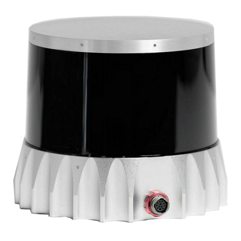
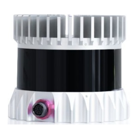
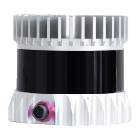
Ouster OS1 Instructions for use

OS1HardwareUserManual
For Rev7 Sensors
Ouster
Mar14,2023

Contents
1 Important SafetyInformation 3
1.1 Safety&LegalNotices........................................ 3
1.2 ProperAssembly,MaintenanceandSafeUse . . . . . . . . . . . . . . . . . . . . . . . . . . 6
1.3 SensorCleaning............................................ 8
1.4 Regulatorycompliance........................................ 9
2 Sensor 10
2.1 Overview................................................ 10
2.2 OS1ProductModels ......................................... 10
3 MechanicalInterface 10
3.1 IncludedComponents ........................................ 10
3.2 MechanicalDrawings......................................... 11
3.3 MountingGuidelines......................................... 13
3.4OperatingTemperatures....................................... 15
4 ElectricalInterface 16
4.1 PowerSupplyandOperatingVoltage . . . . . . . . . . . . . . . . . . . . . . . . . . . . . . . 16
4.2 ConnectionthroughtheInterfaceBox . . . . . . . . . . . . . . . . . . . . . . . . . . . . . . . 16
4.3 DirectCableConnectionandPinout . . . . . . . . . . . . . . . . . . . . . . . . . . . . . . . . 16
5 DigitalIO 19
5.1 SYNC_PULSE_IN........................................... 19
5.2 MULTIPURPOSE_IO(MIO)......................................20
6 OS1CADfiles 21
7 Accessories 21
7.1 Cables ................................................. 21
7.2 InterfaceBox..............................................23
7.3 MountingInterfaceBox ....................................... 31
7.4 PowerSupply .............................................32
8 GPS/GNSS SynchronizationGuide 33
8.1 SettingupyourGPS/GNSS.....................................33
8.2 ConnectingtheHardware......................................34
8.3 ConfiguringtheOusterSensor . . . . . . . . . . . . . . . . . . . . . . . . . . . . . . . . . . . 36
9 Support 36
2

1 ImportantSafetyInformation
1.1 Safety&LegalNotices
The OS1-128, OS1-64, and OS1-32 have been evaluated to be Class 1 laser products per 60825-1:
2014 (Ed. 3) andoperateinthe865nmband.
L’OS1-128,l’OS1-64,etl’OS1-32répondentauxcritèresdesproduitslaserdeclasse1,selonlanorme
IEC60825-1: 2014(3èmeédition)etémettentdansledomainedel’infrarouge,àunelongueurd’onde
de865nmenviron.
FDA 21CFR1040 Notice: OS1-128,OS1-64,and OS1-32complywithFDAperformancestandardsfor
laserproductsexceptfordeviationspursuanttoLaserNoticeNo. 56,datedJanuary19,2018.
Notice FDA 21CFR1040: L’OS1-128, l’OS1-64, et l’OS1-32 sont conformes aux exigences de perfor-
mances établies par la FDA pour les produits laser, à l’exception des écarts en application de l’avis
nº56,datédu19janvier2018.
Thefollowingsymbolsappearontheproductlabelandintheusermanualhavethefollowingmeaning.
Figure 1.1: Class1LaserProduct
Figure 1.2: Caution“SharpEdges”
3

Figure 1.3: Thissymbolindicatesthatthesensoremitslaserradiation.
Figure 1.4: Thissymbolindicatesthepresenceofahotsurfacethatmaycauseskinburn.
CAUTIONS:
TheOS1isahermeticallysealedunit,andisnonuser-serviceable.
Useofcontrols,oradjustments,orperformanceofproceduresotherthanthosespecifiedherein,
mayresultinhazardousradiationexposure.
Use of the OS1 is subject to the Terms of Sale that you agreed and signed with Ouster or your
distributor/integrator. Includedinthesetermsaretheprohibitionsof:
Removingorotherwiseopeningthesensorhousing
Inspectingtheinternalsofthesensor
Reverse-engineeringanypartofthesensor
Permittinganythirdpartytodoanyoftheforegoing
Operating the sensorwithout the attached mount that is shipped withthe sensor, or attaching
the sensor to a surface of inappropriate thermal capacity runs the risk of having the sensor
overheatundercertaincircumstances.
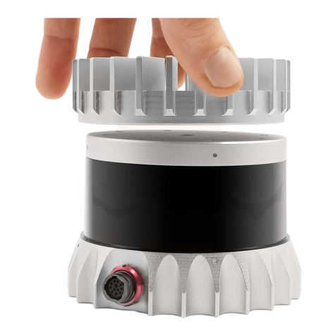
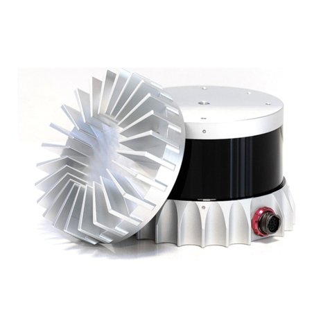
Thislidarsensorfeaturesamodularcapdesigntoenablemoreflexiblemountingandintegration
solutionsforthesensor.
The modular cap design increases design flexibility but it does not remove the need for ther-
mal management on top of the sensor. The attached radial cap serves an important thermal
managementpurposeandthesensorwillnotoperateproperlywithoutacap.
Operationforextendedperiodsoftimewithoutthecapwillresultinsystemerrorsandthesen-
sor overheating. The cap can be replaced with alternative solutions but it cannot be left off
altogether.
Ifyouwishtooperatethesensorwithacustommountingsolution,pleasecontactourFieldAp-
plication Team and we can answer your questions and provide guidance for achieving proper
operations.
4

This product emits Class 1 invisible laser radiation. The entire window is considered to be the
laseraperture. WhileClass1lasersareconsideredtobe“eyesafe”,avoidprolongeddirectview-
ingofthelaseranddonotuseopticalinstrumentstoviewthelaser.
Whenoperatedinanambienttemperature>40�°C,themetallicsurfacesofthesensormaybe
hot enough to potentially cause skin burn. Avoid skin contact with the sensor’s base, lid and
the heatsink when the sensor is operated under these conditions. The sensor should not be
usedin an ambient temperatureabove60°C. The maximumsafetycertifiedambient operating
temperatureis60°C.
PRECAUTIONS:
L’OS1 est une unité hermétiquement scellée, qui ne peut être entretenue ou modifiée par
l’utilisateur.
L’utilisation de commandes, de réglages, ou l’exécution de procédures autres que celles spéci-
fiéesdansleprésentdocumentpeuvententraînerdesrayonnementslaserdangereux.
L’utilisation de l’OS1 est soumise aux conditions de vente signées avec Ouster ou le distribu-
teur/intégrateur,incluantl’interdictionde:
Retirerououvrirdequelquefaçonleboîtierducapteur
Analyserlescomposantsinternesducapteur
Pratiquerlarétro-ingénieriedetouteoupartieducapteur
Autoriserunetiercepersonneàmenerlesactionslistéesci-dessus
L’utilisation du capteur sans le support (fourni avec les capteur) ou sans contact avec une sur-
faceayantdescapacitésthermiquesadéquatespeutentraînerunesurchauffeducapteurdans
certainesconditions.
Ce capteur présente une conception avec un dissipateur thermique supérieur modulaire, ceci
pourapporterplusdeflexibilitédemontageetd’intégrationaucapteur.
Cette conception modulaire augmente la flexibilité de conception mais ne supprime pas le be-
soinde dissipationthermique au-dessus ducapteur. Ledissipateur thermiqueradial fourniest
essentiel à une bonne gestion thermique. Le capteur ne fonctionnera pas correctement sans
cettepièce.
Uneutilisationprolongéeducapteursansledissipateurthermiquesupérieurpeutrésulteràdes
erreurs système ainsi qu’à une surchauffe du capteur pouvant aller jusqu’à son extinction. Le
dissipateurthermiquefournipeutêtreremplacéparuneautresolutiondedissipationthermique
adéquate,maisnedoitpasêtresimplementretiré.
Sivoussouhaitezutiliservotrecapteuravecune dissipation thermique personnalisée,mercide
contacternotreÉquipeSupportquipourrarépondreàvosquestionsetvousapporterlesupport
etleconseilnécessaire.
Ce produit émet un rayonnement laser invisible de classe 1. L’ouverture de sortie du laser est
constituéeparlafenêtreducapteurdanssatotalité. Mêmesileslasersdeclasse1nesontpas
considéréscommedangereuxpourlesyeux,neregardezpasdirectementlerayonnementlaser
defaçonprolongéeetn’utilisezpasd’instrumentsoptiquespourobserverlerayonnementlaser.
5

Lorsd’une utilisation àtempératureambiantesupérieure à 40°C, lasurfacemétalliquedu cap-
teur peut présenter des risques de brûlurespour la peau. Dans ces conditions, il est important
d’éviter tout contact avec la partie supérieure, la base ou le dissipateur thermique du capteur.
Le capteur ne doit pas être utilisé à une température ambiante supérieure à 60˚C. 60˚C est la
températuremaximalecertifiéed’opérationsûreducapteur.
Equipment Label: Includes model and serial number and a notice that states the unit is a Class 1
LaserProduct,isaffixedonthebaseextension. Itisonlyvisibleaftertheattachedmountwithwhich
theSensorisshipped,isremoved. ForlocationdetailspleaserefertofigureSensorComponents(Me-
chanical Drawings) intheMechanicalInterfaceSection.
L’étiquettedel’équipement,comprenantlemodèle,lenumérodesérie,etlaclassificationduproduit
laser (ici, classe 1), est apposée au-dessous de la base du boîtier du capteur. Il n’est visible qu’après
avoirretirélediffuseur dechaleuraveclequellecapteurest expédié. L’emplacementest décrit avec
précisiondanslasectionSensor Components (Mechanical Drawings).
ElectromagneticCompatibility: TheOS1is an FCC47CfR 15Subpart Bdevice. This devicecomplies
with part 15 of the FCC Rules. Operation is subject to the following conditions: (1) This device may
not cause harmful interference, and (2)this device mustaccept any interferencereceived, including
interferencethatmaycauseundesiredoperation.
“Ouster” and “OS1” are both registered trademarks of Ouster, Inc. They may not be used without
expresspermissionfromOuster,Inc.
Ifyouhaveanyquestionsabouttheabovepoints,contactusatOusterLegal.
1.2 ProperAssembly,MaintenanceandSafeUse
TheOS1canbeeasilysetupbyfollowingtheinstructionsoutlinedinMountingGuidelines. Anymount-
ingorientationisacceptable. Eachsensorisshippedwithanattachedmountthatcanbeusedfortest
ornormalusewithinthespecifiedoperatingconditions. Thesensormayalsobeaffixedtoanyother
user specific mount of appropriate thermal capacity. Please contact Ouster for assistance with ap-
provingtheuseofuserspecificmountingarrangements.
Any attempt to utilize the sensor outside the environmental parameters delineated in the OS1
datasheetmayresultinvoidingofthewarranty.
When power is applied, the sensor powers up and commences boot-up with the laser disabled. The
boot-upsequenceisapproximately60sinduration,afterwhichtheinternalsensoropticssubassem-
blycommencesspinning,thelaserisactivated,andtheunitoperatesinthedefault1024x10Hzmode.
Whenthesensorisrunning,andthelaserisoperating,afaintredflickeringlightmaybeseenbehind
theopticalwindow.
NotethattheOS1utilizesan865nminfraredlaserthatisonlydimlydiscernibletothenakedeye. The
sensoris fullyClass 1eyesafe,though Ousterstronglyrecommendsagainst peeringintothe optical
windowatclose rangewhilethe sensoris operating. Oustersensorsareequippedwith amulti-layer
seriesofinternalsafetyinterlockstoensurecompliancetoClass1LaserEyeSafelimits.
TheOS1isahermeticallysealedunit,andisnotuser-serviceable. Anyattempttounsealtheenclosure
hasthepotentialtoexposetheoperatortohazardouslaserradiation.
6
Thesensoruser interfacemaybe used toconfigurethesensortoanumber ofcombinationsof scan
ratesand resolutionsotherthanthe defaultvaluesof1024x 10 Hzresolution. Inall availablecombi-
nations,theunithasbeenevaluatedbyanNRTLtoremainwithintheclassificationofaClass1Laser
DeviceasperIEC60825-1:2014(Ed. 3).
Assemblagecorrectet utilisationsûre
L’OS1s’installefacilementenfixantlabasesurunsupportpercéde trousconcordants,etensuivant
les instructions d’interconnexion décrites dans la section Mounting Guidelines. Toute orientation de
montage est acceptable. Chaque capteur est expédié équipé d’un dissipateur de chaleur, utilisable
enphase de testet enconditions normales. Néanmoins toutautresupportprésentant unecapacité
thermiqueappropriéepourl’applicationdel’utilisateurpeutêtreutilisé. VeuillezcontacterOusterdans
lecasoùunmontagespécifiqueàvotreapplicationseraitnécessaire.
Toute tentative d’utilisation du capteur en dehors des paramètres environnementaux définis dans la
fichetechniquedel’OS1peutentraînerl’annulationdelagarantie.
Lorsquelecapteurestsoustension,celui-cidémarreetcommencesoninitialisationaveclelaserdés-
activé. Letempsdedémarrageestd’environ60s,aprèsquoilesous-systèmeoptiqueentreenrotation
etlelaserestactivé,lecapteuropèrealorsdanssonmodepardéfautde1024x10Hz. Lorsquelecap-
teur est en marche et que le laser est activé, on peut apercevoir une faible lumière rouge vacillante
derrièrelavitreteintée. L’OS1utiliseunelongueurd’ondesinfra-rougede865nmnmàpeinepercep-
tible pour l’œil humain, et le rayonnement laser IR émis est sans danger pour les yeux. Cependant,
bienquelesrayonnementslaserdeclasse1soientsansdangerdansdesconditionsraisonnablement
prévisibles,Ousterrecommandefortementdenepasregarderfixementlavitreteintéependantquele
capteurestenmarche. L’OS1estuneunitéhermétiquementscellée,quinepeutpasêtreentretenue,
modifiée ou réparée par l’utilisateur. Toute tentative d’ouverture du boîtier a pour risque d’exposer
l’opérateuràunrayonnementlaserdangereux.
L’OS1 est une unité hermétiquement scellée, qui ne peut pas être entretenue, modifiée ou réparée.
Toutetentatived’ouvertureduboîtierapourrisqued’exposerl’opérateuràunrayonnementlaserdan-
gereux.
LescapteursOustersontéquipésd’unesériededispositifsdesécuritéàplusieursniveaux,defaçonà
assurerentoutescirconstanceslerespectdeslimitesd’irradiancecorrespondantauxrayonnements
lasersdeclasse1,sansdangerpourlesyeux.
L’interfaceutilisateurdulogicielducapteurpeutêtreutiliséepourconfigurerlecapteurselonuncer-
tainnombredecombinaisonsdevitessesdebalayageetderésolutionsautresquelesvaleursutilisées
pardéfaut,respectivementde1024x10Hz.
7

1.3 SensorCleaning
AllOusterSensorwindowaremadefrompolycarbonate. Basedonthesensorusageyoumayseedust,
bugsand/orlayersofmud/debrisonthewindow. Beforeyouattempttocleanyoursensor,pleaseread
theinstructionsbelowonbestpracticesforcleaningOusterSensors.
RequiredMaterials:
Fewcleanmicrofibercloths
Warmwater
Mildliquiddishwashingsoap
Spraybottlewithcleanwater
Spraybottlewithmildsoapywater
99%Isopropylalcohol
Warning:
Avoidgettingwaterintothepowerconnector.
Avoidusinghardwaterwhencleaningthesensor.
Donotuseacetonetocleanthewindow. Itwillembrittlethepolycarbonate.
Donotwipedirtdirectlyfromthesensor. Sprayitoffwithwarmwaterfirst.
Procedure:
Usingthe99%isopropylalcoholandacleanmicrofibertowel,wipeawaybugs/mud/debrisfrom
thesensor.
Spraythesensorwithwarm,mild-soapywaterandgentlywipethesensorwithacleanmicrofiber
towel. Wipealongthecurveofthesensor,nottop-to-bottom(thinkmovingwiththegrain).
Spraythesensorwithcleanwatertorinseoffthesoapanddrywithasecondmicrofibertowel.
Enjoyyourcleanwindow.
8

1.4 Regulatorycompliance
ForUSA
LaserSafety:
IEC/EN60825-1:2014Class1eyesafe
FDAUS21CFR1040Notice56Class1
ProductSafety:
UL62368-1
CSA22.2No. 62368-1-19
EMC:FCC47CFRPart15,SubpartB,ClassA
ForEU
LaserSafety:
IEC/EN60825-1:2014Class1eyesafe
ProductSafety:
EN/IEC62368-1
EMC EN55032:2012/AC2013;CISPR32:2015
EN55024:2010;CISPR24:2010
EN61000-3-2:2014
EN61000-3-3:2013
Figure 1.5: CE,RoHS&UKCAcompliant
Note: (ForUKCACompliance)
OusterUK(Ltd): 125PrincesStreet,EdinburghEH24AD,Scotland,UnitedKingdom.
ContactPerson: NeilCalder,PhoneNumber: +44(0).131.563.9078
9

2 Sensor
2.1 Overview
The OS1 offers an industry-leading combination of price, performance, reliability, size, and weight. It
isdesignedforindoor/outdoorall-weatherenvironmentsandalonglifetime.
The OS1 family of sensors consist of three models, the OS1-128, OS1-64, and OS1-32, with differing
verticalresolution,butidenticalmechanicaldimensions.
Forthepurposesofthisdocument,theterm“OS1”referstothefamilyofsensors,andonlywherethere
isadifferenceinperformancewilleachmodelbereferredtobyitsspecificmodeldesignation.
ThecontentsofthismanualareapplicableonlytoRev7sensors. Pleasefindthestickeronthetopcap
orthebottomofthesensorthatwillhavealltheinformationregardingproduct type,serial number and
part number. For all other sensor hardware revisions, please refer to their respective hardware user
manual.
2.2 OS1ProductModels
TheOS1isavailablewith128,64,or32beamsofverticalresolutionandwithUniform,Gradient,Above
Horizon,orBelowHorizonbeamspacingoptions. Productspecsandmoreinformationonthesecon-
figurationscanbefoundontheOS1productpage.
3 MechanicalInterface
3.1 IncludedComponents
TheOS1isshippedwiththefollowingitems:
Sensor
Interfaceboxcable/connector
24VAC/DCpowersupply(2meters)
RJ45cable(1meter)
BaseplateMount
10

3.2 MechanicalDrawings
Table3.1: SensorComponents(MechanicalDrawings)
Table3.2: MechanicalDrawings(cntd.)
11

Table3.3: MechanicalDrawings(cntd.)
Table3.4: MechanicalDrawings(TopCaps)
12

Table3.5: MechanicalDrawings(Baseplates)
DownloadableCADfilesfortheOS1canbefoundonlineatOusterDownloadPage
Warning: ThewateringressprotectionratingforthesensorisonlyvalidiftheI/Ocableisplugged
into the panel mount connector on the base of the sensor, and the locking collet rotated to the
properly locked condition. The cable and plug are an element of the sensor ingress protection
system. Withouttheconnectedcabletheingressprotectionratingmaybecompromised. Bending
the cable at a sharp angle directly after egress from the plug over mold should also be avoided.
Sharpbendsandhighaxialstressesonthecableimmediatelyadjacenttotheplugovermoldmay
createa moistureingresspathintothe connector. PleaserefertoCable Characteristics formore
informationonminimumbendradiusrequirements.
3.3 MountingGuidelines
Our sensors ship with modular mounting options. The sensor can be mounted in any orientation.
Propermountingwillensureoptimalsensorperformanceandefficientheatdissipation.
Mounttoa materialwithhigh thermalconductivity. Thefollowingarerecommendedaluminum
alloysandtheirthermalconductivities:
1) 6061: 167W/m-K
2) 7075: 130W/m-K
3) 2024: 121W/m-K
Ensureinterfacesarecleanandfreefromdebris.
M3screwsareformountingthesensordirectlytothesurface. M8screwsareusedformounting
thebase platetothesurface. ThescrewholepatternispresentedintheSensordrawingabove
Sensor Components (Mechanical Drawings).
13

Torque bolts appropriately for the mount material and bolts. A torque of 146cNm is recom-
mendedfora2stainlesssteelscrews.
UseTIM(ThermalInterfaceMaterial)foranyirregularorunmachinedsurfaces.
Donotoverconstrainthesensorifmountingtoboththetopandthebottom.
Note: Donot mount thedevicesolely fromthe top. Theprimary mountingattachmentsiteisatthe
bottomofthedeviceasitensuresadequatemechanicalsupportandruggedness.
Useathermallyconductivepadtoensuregoodconductivitywhilenotoverconstraining.
Ensure your implementation maintains the base and top of the sensor at no greater than 25ºC
aboveambientwithanambientlessthan50ºC.
Theshapeofanyheatsinkshouldmaximizethesurfaceareaforfreeandforcedconvectionwhile
beingthickenoughtoallowtheheattoconductthroughthematerial.
Mountingonadrywall:
When mounting a sensor (needs to be mounted on a baseplate) on a drywall or a false ceiling,
Ousterrecommendsthemountingmeansmustbeabletosupport3Xtheweightofthesensor.
Checkthewall conditionandmakesureitsnotaging. If your drywallisageing or deteriorating,
it’slikelytobowandbendwiththeaddedweightofthesensor,baseplateandcablesconnected
to it. This could cause a potentially dangerous situation where the wall anchors could pull out
andleavethesensorhangingordropdown.
CAD Files and mechanical drawings are provided by Ouster to verify proper sensor and base
platedimensionsthatcanhelpmeasuringthesurfaceforproperplacementandmounting.
Check for studs using a stud finder. As these studs are hidden behind drywall, you’ll need to
locatethem (ifavailable) with astudfinder. Laythestud finder flatonthewallwhereyouwant
to position your sensor and turn it on. Slowly move it across the wall from left to right until it
beepsorlightsup. Notethelocationwithapencilmarkandcontinuealongthewalluntilyoufind
thenextstud. Continuethisprocessuntilyou’vefoundallthestudswhereyouplantoinstallthe
sensor.
Drillpilotholesandmountthesensorcarefully. Makesureyoucheckforproperinstallationand
thatallscrewsaretightlyfit.
14

Mountingonaconcretewall:
Check the wall conditions before drilling any pilot holes and make sure there are no cracks or
moldsorhollowbricks.
UsingtheCADFilesandmechanicaldrawingsprovidedbyOuster,markatemplatewithapencil
onthewallwhereyouwanttomountthesensor(needstobemountedonabaseplate).
Usingappropriatedrillbit,drillpilotholesaccordinglyandmountthesensorcarefully.
Forconcretewalls,makesuretochooseanappropriatestainlesssteelscreworawedgeanchor
basedonthetypeofwall.
Makesureyoucheckforproperinstallationofthesensorandthatallscrewsaretightlyfit.
Note: If you do not feel comfortable following the steps above for mounting please contact Ouster
Supportsowecanwalkyouthroughthestepsthoroughly.
Warning: The sensor cables are not rated for running in any environmental air handling space,
including source ducts or air returns that are commonly the spaces above false ceilings and are
notincompliancewithNFPA70(USNEC),300.22(B)and(C).
PleaserefertosectionMounting Interface Box formoreinformationonmountingtheinterfacebox.
3.4 OperatingTemperatures
Thermal requirements specific to Rev7 are listed below. The sensor has three operating states in
order to manage high temperatures: Active,Shot Limiting, or Inactive. In the standard Active state
thesensor willperformto therangeand precisionspecifications of the datasheet. Whenthe sensor
reachesacertaintemperature(seetablebelowforreference),itentersShotLimitingstateandissues
analert.
In Shot Limiting state, the sensor reduces power to the lasers in order to reduce the thermal load.
Whileinthisstate,sensorrangeandprecisionmaydegradebyupto20%. Whenthesensorreaches
themaximumoperatingtemperaturespecifiedbelow,thesensormaybecomeInactiveandshutoff.
15

Table3.6: MaximumthermalperformanceforRev7OS1Sensor
ConvectiveAirTempwithRadialHeatsink
andStandardBase
Maxtempbeforeshotlimiting 52ºC
Tempthatshotlimitingsaturated(sensormayturnoff
abovethistemperature) 60ºC
4 ElectricalInterface
4.1 PowerSupplyandOperatingVoltage
TheOS1Sensorsaredesignedtooperatebetween12Vand24Vnominalinputvoltage. Alowvoltage
warningwillbetriggeredifthevoltageatthesensorconnectordropsbelow9.5V.Thesensorwillshut
downif thisinput voltagedrops to9V. Themaximum input voltageis 34Vforthe OS1 sensor. When
usedwithouttheprovidedinterfacebox,ensurethatthepowersupplyiscompliantwiththeoperating
voltagespecifiedaboveandisatleast20W.
Note: Ifoperatingatcold conditions the peakpowerconsumptionisbetween22Wand28W. Peak
power consumption is 28 W if operated at -40ºC. Ouster recommends use of a power (no less than
30W)ifusinginoutdoorconditions. PleasecontactourFieldApplicationTeamcanansweryourques-
tionsandprovideguidanceforachievingproperoperations.
4.2 ConnectionthroughtheInterfaceBox
The Interface Box that accompanies the OS1 is designed to allow the sensor to be operated for test
andevaluationpurposesinindoorenvironmentsonly. Itcanbeconnectedtothe sensor with a cable
equipped with connectors. It allows the sensor to be powered up and provides access to the sensor
gigabitEthernetInterfaceviaastandardRJ45connector. DCPowertothe sensor isprovidedtothe
InterfaceBoxbytheaccompanying24VDCpowersupply.
4.3 DirectCableConnectionandPinout
The OS1 can be operated without the use of an Interface Box. In this case, a “pigtail” cable should
be used by the user following the Pinout presented below. When used with direct cable connection,
thesensorshouldstillbeoperatedwithintheoperatingvoltagespecifiedinsectionPowerSupplyand
Operating Voltage.
16

CablePinoutDiagramforType 1, 2 and 3 (1000BASE-T)
Table4.1: Type1,2,3(1000BASE-T)
Fig.4.1: Type1,2,3(1000BASE-T) Fig. 4.2: Type 3 Zinc and Stainless Steel CAD
Drawing
Table4.2: PinoutandwiregaugesforTypes1,2,and3(1000BASE-T)cables
Function Pin
No. Wire
Color Type-1,
24V Type-2,
24V Type-3,
12V Twisted
with Color
(Display)
VCC 1 Red 22AWG 22AWG 18AWG N/A
GROUND 7 Black 22AWG 22AWG 18AWG N/A
MULTI-
PURPOSE_IO 3 Purple 26AWG 28AWG 28AWG N/A
SYNC
_PULSE_IN 2 Yellow 26AWG 28AWG 28AWG N/A
Ethernet
BI_DA+ 5 White
/Orange 26AWG 28AWG 28AWG Orange
Ethernet
BI_DA- 4 Orange 26AWG 28AWG 28AWG White
/Orange
Ethernet
BI_DB+ 8 White
/Green 26AWG 28AWG 28AWG Green
Ethernet
BI_DB- 6 Green 26AWG 28AWG 28AWG White
/Green
Ethernet
BI_DC+ 9 Blue 26AWG 28AWG 28AWG White
/Blue
Ethernet
BI_DC- 10 White
/Blue 26AWG 28AWG 28AWG Blue
Ethernet
BI_DD+ 12 White
/Brown 26AWG 28AWG 28AWG Brown
Ethernet
BI_DD- 11 Brown 26AWG 28AWG 28AWG White
/Brown
17

Note: Cable pinout for Type 3 cables are the same for both Zinc and Stainless Steel connectors.
Type 1 andType 2 cablespecificationsareforreferenceonlyareNO longer available forpurchase.
CablePinoutDiagramforType 4 (1000BASE-T1)
Table4.3: Type4(1000BASE-T1)
Fig.4.3: Type4(1000BASE-T1) Fig.4.4: Type4(1000BASE-T1)CADDrawing
Table4.4: PinoutandwiregaugesforType4(1000BASE-T1)cables
NetName Pin
No. Wire
Color Type-4,
Base1000T1 Twisted
with Color
(Display)
VCC 1 Red 18AWG NA
GROUND 7 Black 18AWG NA
MULTIPURPOSE_IO 3 Purple 28AWG NA
SYNC_PULSE_IN 2 Yellow 28AWG NA
EthernetBI_DA+ 12 Blue 26AWG White
EthernetBI_DA- 11 White 26AWG Blue
Warning: OusterisnotresponsibleforanyerrorsinwiringasaresultofbypassingtheInterface
Boxandthisactivitymayresultinvoidingofyourwarrantyifitresultsindamagetothesensor.
Thefollowingguidelinesfordirectcable connectionassume useof theOuster-provided24V1.5A
powersupply. Oustercannotbeheldresponsiblefordamagetothedeviceifanalternateisused.
18

5 DigitalIO
5.1 SYNC_PULSE_IN
SYNC_PULSE_IN is a dedicated input channel that is accessible from the Interface Box. This channel
expectsaninput pulse sequencewhich canbeused fortime synchronization. Refertothe Firmware
User Manual for more information on configuring this input. Any references to pulse polarity in this
documentreferencesthesignalpolarity ontheSYNC_PULSE_IN pinof the sensor. Thisinput channelis
protectedbyanopto-isolatorwhichwilldraw5mAatfulloperation.
Table5.1: SYNC_PULSE_INInterfaceRequirements
Parameter MinVoltage MaxVoltage Min Driver Current
LOGICLOW -30V 2V N/A
LOGICHIGH 2.9V 30V 3mA @3.3V~5V, 5mA
at24Vandhigher
SYNC_PULSE_IN Interface requirements were tested with 2 m cable Interface Box connection at 2
MHz.When GPIO has 5 mA drive strength minimum, GPIO can be directly connected to the
SYNC_PULSE_IN pinoftheInterfaceBoxheader. Thisisthemostcommoncaseandhasbeentested
to work on common Arduino microcontroller series. Typical common logic levels of 3.3 V, 5 V
GPIOofmicrocontrollerscanproducedrivestrengthof5mAmin(Arduino,MSP430,etc.).
If the 5 mA drive strength minimum cannot be met, a buffer circuit is required to drive
SYNC_PULSE_IN.Examplecircuitsareprovidedforcommon3.3Vand5Vlogic.
Figure 5.1: ExampleCircuitfor3.3V
19

Figure 5.2: ExampleCircuitfor5Vlogic
5.2 MULTIPURPOSE_IO(MIO)
MULTIPURPOSE_IO (MIO)isaconfigurableinputoroutputchannelaccessiblefromtheInterfaceBox. De-
tailedinformationonhowtoconfigurethischannelusingthesensorTCPinterfacecanbefoundinthe
APIguide. Bydefaultthischannelisdisabled.
WhenthischannelisconfiguredasanOUTPUT,theMIO sendsapulsesequencethatcanbeusedfor
timesynchronizationoreventtriggeringoutsidethesensor. Forafulldescriptionofoutputpulsetrig-
geringoptions,refertotheFirmwareUserManualformoreinformation. Thisoutputisanopto-isolated
opencollectorcircuit,relyingonanexternallyprovidedpull-upresistor. Thisresistorisprovidedfora
typical3.3V/5VapplicationaspartoftheInterfaceBoxcircuitry.
Table5.2: MULTIPURPOSE_IO-OUTPUTInterfaceRequirements
Parameter Min Max
PullUpVoltage 3.3V 24V
SinkingCurrent N/A 25mA
When this channel is configured as an INPUT, the MIO can accept a standard NMEA $GPRMC UART
message. These messages are a common way for GPS systems to share timestamp information in
UTCtimeformat. Moreinformationon this packetstructureandsupported baud ratescan befound
intheTimeSynchronizationsectionoftheFirmwareUserManual.
Table5.3: MULTIPURPOSE_IO-INPUTInterfaceRequirements
Parameter MinVoltage MaxVoltage Min Driver Current
LOGICLOW -30V 2V N/A
LOGICHIGH 2.9V 30V 3mA @3.3V~5V, 5mA
at24Vandhigher
Above are tested with a 35m (200uH inductance) Interface Box at 115200 Baud.
20
Other manuals for OS1
1
Table of contents
Other Ouster Accessories manuals

Ouster
Ouster OS0-128 Instructions for use

Ouster
Ouster OS-1-64 Installation manual

Ouster
Ouster OS1-128 Instructions for use

Ouster
Ouster OS2 Instructions for use

Ouster
Ouster OS0 Instructions for use

Ouster
Ouster OS2 Instructions for use

Ouster
Ouster OS0 Instructions for use

Ouster
Ouster OS-1-16 Safety guide
Popular Accessories manuals by other brands

Emmaljunga
Emmaljunga nxt Twin manual

Wulian
Wulian WL-ZSKWNPW-W3160-01 user manual

Datalogic
Datalogic S51-PA Series instruction manual

Pilot Communications
Pilot Communications BRFN-30EF Use and care guide

Young Living
Young Living Desert Mist Operation manual

Patton electronics
Patton electronics 3080/V24 Installation and operation manual