manuals.online logo
Brands
  1. Home
  2. •
  3. Brands
  4. •
  5. Siemens
  6. •
  7. Accessories
  8. •
  9. Siemens S 564 User manual

Siemens S 564 User manual

instabus EIB
Technical Product Information
August 2005
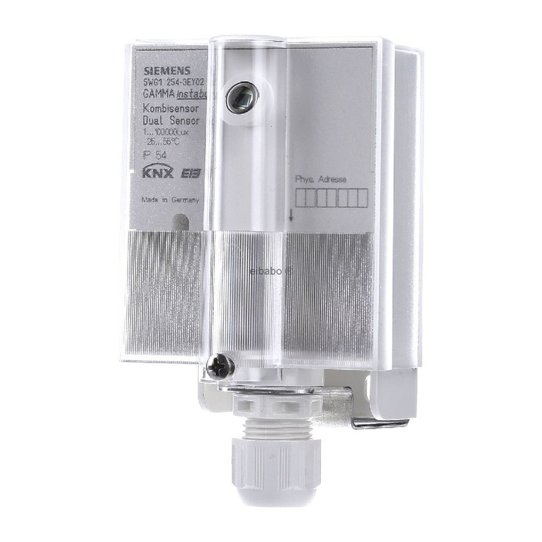
Socket outlet switch wave S 564 5WG3 564-7AB11
Siemens AG S 564, 4 pages Technical Manual
Automation and Drives Group
Electrical Installation Technology ©Siemens AG 2005 Update: http://www.siemens.de/gamma
P.O. Box 10 09 53, D-93009 Regensburg Subject to change without prior notice
2.20.7.1/1
Product and Applications Description
The socket outlet switch wave S 564 is an adapter plug
for the remote control of electrical devices connected to
socket outlets like floor lamps or radios by controlling a
relay via radio frequency.
The socket outlet switch wave is a product from the
range of GAMMA wave devices and therefore uses the
standardized KNX RF protocol.
Besides the remote operation using RF switches (with
function switching or scene control) or other RF sensors
like smoke detectors or door contacts, the socket outlet
switch wave can be controlled directly by a push button
on the device. A LED indicates the actual switching
status.
The commissioning of the socket outlet switch wave is
carried out without any additional means via push button
actions (Easy mode Push Button: EP).
There are two different operation modes for the socket
outlet switch wave:
Normal function
•Operation of the integrated socket outlet locally
•Remote operation of the integrated socket outlet via
RF switches or other RF senders
Special function
•Establishing connections with other radio control com-
ponents
•Deleting connections with other radio control compo-
nents
Operation
After a short operation of the push button (less than 10s)
the local socket outlet is switched ON or OFF respec-
tively.
After a long operation (at least 10s) the device is
switched to special function mode. In this mode the
socket outlet switch wave can be connected with other
devices or an established connection can be released.
If the push button is operated again long (at least 10s)
while in special function mode, all connections with other
devices will be deleted.
Installation Instructions
Caution:
•The device may be used in interior installations in dry
rooms only.
•Occasionally the transmission range may be influ-
enced by structural conditions (e.g. reinforced con-
crete) or electric / electronic sources of interference.
•A minimum distance of 0.5m must be maintained
between the transmitter and the relevant receivers.
•Though the radio transmission is carried out in the
safe 868MHz range, disruptions to the radio transmis-
sion cannot be excluded.
•The radio transmission is not suitable for security
applications.
VWARNING
•The device must not be opened.
•The device must not be combined with other adaptor
plugs
•The prevailing safety and accident regulations must be
observed.
Technical Specifications
Mechanical specifications
•Housing: plastic
•Mounting form: socket outlet adapter for countries
using socket outlets with side grounding contacts (DIN
norm)
•Dimensions (L x W x D):
12,8 x 7,2 x 7,5 cm (incl. contacts)
•Weight: approx. 140g
Power supply
Integrated power supply 230V AC +10% / -15%
instabus EIB
Technical Product Information
August 2005
Socket outlet switch wave S 564 5WG3 564-7AB11
Technical Manual S 564, 4 pages Siemens AG
Automation and Drives Group
Update: http://www.siemens.de/gamma ©Siemens AG 2005 Electrical Installation Technology
Subject to change without prior notice P.O. Box 10 09 53, D-93009 Regensburg
2.20.7.1/2
Connections
•socket outlet receptacle with side grounding contacts
for the connection of any load up to 16A (resistive)
•socket outlet plug with side grounding contacts to be
plugged in any socket outlet receptacle with side
grounding contacts fused with at most 16A.
Breaking capacity
•socket outlet receptacle and plug connected via relay
•Rated voltage; AC 230 V, 50Hz
•Rated current: 16 A
•Switching cycles: > 20.000
if used with Incandescent lamps up to 1000W
Electrical safety
•Pollution degree (according to IEC 60664-1): 2
•Protection (according to EN 60529): IP 20
•Overvoltage category (according to IEC 60664-1): III
•Device complies with EN 60669-2-1 and IEC 60664-1
Electromagnetic compatibility
Complies with EN 60669-2-1, EN 301489, EN 300220
Environmental specifications
•Climatic conditions: EN 50090-2-2
•Ambient operating temperature: - 5 ... + 45°C
•Storage temperature: - 25 ... + 70°C
•Relative humidity (non-condensing): 5% to 93%
Approbation
VDE Approbation in preparation, complies
- Standard
radio frequency wave
easy mode push button EP
CE Norm
Complies with EN 61058-1, DIN VDE 0620, DIN 49440 /
DIN 4944, EMV-regulations (residential building), low
voltage regulations and R&TTE-regulations:
The CE declaration can be inspected at:
SIEMENS AG
Siemensstraße 10
D-93055 Regensburg
Frequency band
868 MHz (transmission is not susceptible to interference;
frequency band reserved for system and security applica-
tions)
Range of radio control
approx. 100 m (applying to free field applications)
Location and Function of Display and
Operating Elements
A1
A2
A3
A4
A1 socket outlet receptacle with side grounding contacts
A2 Status LED
A3 Push button for local operation
A4 socket outlet plug with side grounding contacts
Mounting and commissioning
Mounting: (Figure 2)
The socket outlet switch wave is plugged into a socket
outlet receptacle with side grounding contacts manually.
To avoid radio interference the socket outlet switch wave
should be mounted in a way that the cable of the
switched device does not run across the housing.
Dismantling:
Remove the socket outlet switch wave manually out of
the socket outlet receptacle.
instabus EIB
Technical Product Information
August 2005
Socket outlet switch wave S 564 5WG3 564-7AB11
Siemens AG S 564, 4 pages Technical Manual
Automation and Drives Group
Electrical Installation Technology ©Siemens AG 2005 Update: http://www.siemens.de/gamma
P.O. Box 10 09 53, D-93009 Regensburg Subject to change without prior notice
2.20.7.1/3
Commissioning:
The connection e.g. of a push button wave with the
socket outlet switch wave is carried out by pressing the
push button of the push button wave and the push but-
ton of the socket outlet switch wave. To do so, the spe-
cial function must be set for the two devices which have
to be connected with each other. The operating state
and the successful connection are displayed by the
LEDs of both devices.
Connection via radio control:
Connecting a push button wave to a socket outlet switch
wave via radio control:
B1
B2
Figure 3:
B1 push button wave
B2 socket outlet switch wave
1. Socket outlet switch wave: Switch to special func-
tion (B2)
Action:Press the push button for at least 10 seconds.
Display: The LED begins to flash slowly (approx. once
per second) after 10 seconds (switches to special
function).
2. Push button wave: Switch to special function (B1)
Action:Press the push button rocker in the CENTRE for
at least 10 seconds.
Display: The LED of the push button begins to flash
slowly (approx. once per second) after 10 sec-
onds (toggling to the special function).
.
3. Push button wave: Transmit a linking telegram (B1)
Action:Brief operation (up to 0.4 sec.) of the push button
rocker at the TOP, CENTRE or BOTTOM.
Display: The LED of the push button wave flashes rapidly
(3 times per sec.) for approx. 3 seconds if the con-
nection has been established successfully. The
LED is then extinguished and the push button ex-
its the special function. The LED of the socket out-
let switch wave flashes in the same way and the
special function mode is terminated.
Note: There is only a limited period available for the
connection as both devices exit the special function after
2 minutes.
The connection of the socket outlet switch wave with the
push button wave is complete. When the push button
wave is operated the socket outlet switch wave will be
switched as well via the radio connection.
If the connection has failed (e.g. if the distance is too
great), both devices exit the special function after
approx. 2 minutes, without confirming the success of the
connection by flashing rapidly.
This procedure must be repeated if the socket outlet
switch is to be connected with other push buttons or
sensors (up to 10 connections possible).
Procedure for deleting a connection:
Single connections can be deleted by reconnecting an
already known device.
Deletion of the connection between a push button wave
and the socket outlet switch wave:
1. Socket outlet switch wave: Switch to the special func-
tion
2. Push button wave: Switch to the special function
3. Push button wave: Trigger a linking telegram
The connection between the socket outlet switch wave
and the push button wave is thereby deleted.
Deleting all connections and resetting to the sup-
plied state:
1. Switch the push button wave to the special function.
Action:Press the push button for at least 10 seconds.
Display: The LED begins to flash slowly (approx. once
per second) after 10 seconds (switches to the
special function).
2. Reset the device
Action:Press the push button again for at least 10 sec-
onds.
Display: The LED of the push button flashes rapidly (3
times per second) for approx. 3 seconds. The
LED is then extinguished and the socket outlet
switch wave exits the special function.
All connections in this device are deleted. The device is
restored to its initial state.
Connections to the socket outlet switch wave in other
devices are retained and must likewise be deleted.
instabus EIB
Technical Product Information
August 2005
Socket outlet switch wave S 564 5WG3 564-7AB11
Technical Manual S 564, 4 pages Siemens AG
Automation and Drives Group
Update: http://www.siemens.de/gamma ©Siemens AG 2005 Electrical Installation Technology
Subject to change without prior notice P.O. Box 10 09 53, D-93009 Regensburg
2.20.7.1/4
Exiting the special function:
If the socket outlet switch wave is operated in special
function mode, this state is terminated by the following
actions and switched back to normal mode.
1. Receipt of a linking telegram
2. Time out after 2 minutes (no push button actions are
carried out and no linking telegrams are received for
a period of two minutes).
3. Operation of the push button of the socket outlet
switch wave for less than 10s.
Dimension Diagram
Dimensions in mm
72
128
33
37,4
55,6
74,6
General information
•Please send any defective unit to the responsible
Siemens AG branch office.
•Our Technical Support service will advise you on any
further product related questions:
℡+49 (0) 180 50 50-222
"+49 (0) 180 50 50-223
hwww.siemens.com/automation/support-request

Other Siemens Accessories manuals

Siemens QMX3.P35H Series User manual

Siemens

Siemens QMX3.P35H Series User manual

Siemens SITRANS WS300 User manual

Siemens

Siemens SITRANS WS300 User manual

Siemens QSA2700D Operator's manual

Siemens

Siemens QSA2700D Operator's manual

Siemens Sitrans WM100 User manual

Siemens

Siemens Sitrans WM100 User manual

Siemens 3VL9500 - 4PA30 User manual

Siemens

Siemens 3VL9500 - 4PA30 User manual

Siemens SIWAREX WP251 User manual

Siemens

Siemens SIWAREX WP251 User manual

Siemens QFA3100 Service manual

Siemens

Siemens QFA3100 Service manual

Siemens SIMATIC RF300 User guide

Siemens

Siemens SIMATIC RF300 User guide

Siemens SIMATIC VS120 User manual

Siemens

Siemens SIMATIC VS120 User manual

Siemens QAF63 Series Instruction manual

Siemens

Siemens QAF63 Series Instruction manual

Siemens 6DR4004-6NN Series User manual

Siemens

Siemens 6DR4004-6NN Series User manual

Siemens SITRANS FC430 Quick start guide

Siemens

Siemens SITRANS FC430 Quick start guide

Siemens SIWAREX WP241 User manual

Siemens

Siemens SIWAREX WP241 User manual

Siemens SITRANS WS300 Service manual

Siemens

Siemens SITRANS WS300 Service manual

Siemens 3VL9400-4W.30 User manual

Siemens

Siemens 3VL9400-4W.30 User manual

Siemens SITRANS WW300 User manual

Siemens

Siemens SITRANS WW300 User manual

Siemens AP261 User manual

Siemens

Siemens AP261 User manual

Siemens DELTA 5TC1 01 Service manual

Siemens

Siemens DELTA 5TC1 01 Service manual

Siemens SIWAREX JB User manual

Siemens

Siemens SIWAREX JB User manual

Siemens QAA2391.EWTC User manual

Siemens

Siemens QAA2391.EWTC User manual

Siemens QFA2000 User manual

Siemens

Siemens QFA2000 User manual

Siemens QBM3700 Series User manual

Siemens

Siemens QBM3700 Series User manual

Siemens SITRANS CU02 User manual

Siemens

Siemens SITRANS CU02 User manual

Siemens A80850 User manual

Siemens

Siemens A80850 User manual

Popular Accessories manuals by other brands

Harvest TEC 600 Operation manual

Harvest TEC

Harvest TEC 600 Operation manual

cimuka CT Series user manual

cimuka

cimuka CT Series user manual

Binder BF 53 operating manual

Binder

Binder BF 53 operating manual

icoms TMA-122 user guide

icoms

icoms TMA-122 user guide

Shinko Denshi UF-620 instruction manual

Shinko Denshi

Shinko Denshi UF-620 instruction manual

REV Ritter Funk-Gong WC624HS manual

REV Ritter

REV Ritter Funk-Gong WC624HS manual

Kathrein ESD 64 manual

Kathrein

Kathrein ESD 64 manual

Vicinoate 158746.01 user manual

Vicinoate

Vicinoate 158746.01 user manual

Garland GIU 3.5 KW parts list

Garland

Garland GIU 3.5 KW parts list

NTI XTENDEX VOPEX-C5SV-x Installation and operation manual

NTI

NTI XTENDEX VOPEX-C5SV-x Installation and operation manual

strex SP221 user manual

strex

strex SP221 user manual

Emerson Rosemount 328A Reference manual

Emerson

Emerson Rosemount 328A Reference manual

Kohler K-4709 Homeowner's guide

Kohler

Kohler K-4709 Homeowner's guide

eloop E53 user manual

eloop

eloop E53 user manual

DeWalt DCHJ060 instruction manual

DeWalt

DeWalt DCHJ060 instruction manual

Omron F3S-TGR-CL_B Installation and operation manual

Omron

Omron F3S-TGR-CL_B Installation and operation manual

SICK W4F operating instructions

SICK

SICK W4F operating instructions

Lippert 2021130655 Installation and owner's manual

Lippert

Lippert 2021130655 Installation and owner's manual

manuals.online logo
manuals.online logoBrands
  • About & Mission
  • Contact us
  • Privacy Policy
  • Terms and Conditions

Copyright 2025 Manuals.Online. All Rights Reserved.