Outback RCPR03 User manual
RCPR/03
INSTALLATION OF ‘OUTBACK’ROOF CONSOLE
PRADO 120 series 02/03 –09/09 Part No: RCPR03
Failure to connect coloured wiring correctly and tape up all connections as described in following
instructions will result in an electrical short and void console warranty.
For this installation you will need a hand held Phillips screwdriver, short Phillips screwdriver, electric or
battery drill, ‘stubby’3.5mm drill bit, steel ruler and insulation tape.
VEHICLE PREPARATION:
Swing Sun Visors around to side and lay flat to roof for ease of installation.
Remove map light assembly. To do this, slide a steel ruler up under front edge of light surround (front edge
facing windscreen). Lever map light assembly downwards slightly; grip with fingers and pull down out of
holding clips. Remove interior light in the same fashion; put both in a safe place for refit upon sale of vehicle.
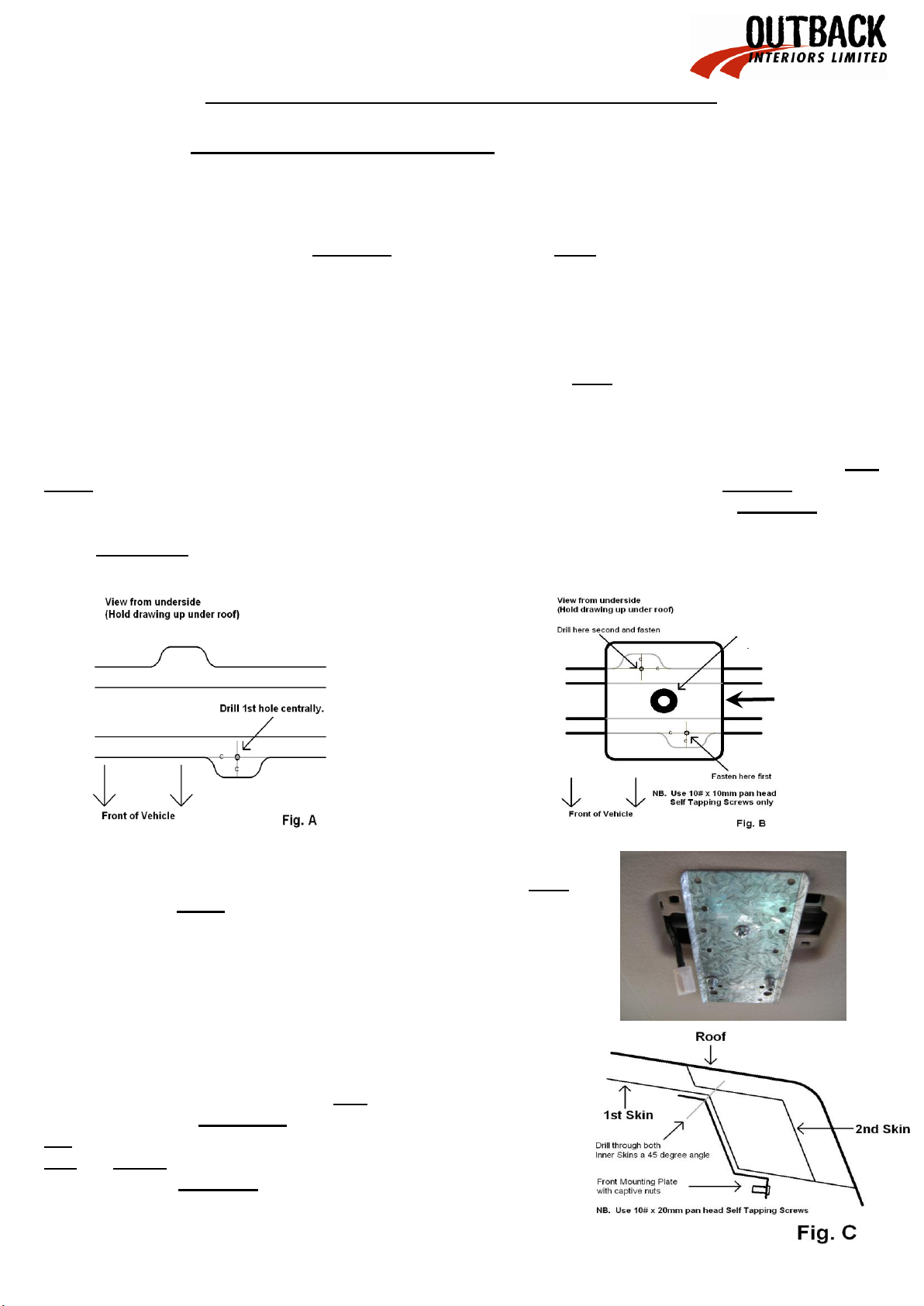
Rear Fixing Plate Installation: Insert ‘stubby’ 3.5mm drill bit into electric or battery drill ensuring only
20mm of drill bit protrudes from chuck. From where you have removed the interior light carefully drill a hole
centrally in one of the ‘ears’located in the roof support frame (see Fig. A below). Using a hand held Phillips
screw driver fix Fastening Plate to drilled hole with a 10# x 10mm self tapping screw ensuring captive nut
points downwards. Now carefully drill through other hole in plate and fasten using remaining 10# x 10mm
screw. Press fit 14mm plastic spacer over captive nut (see Fig. B below).
Fasten Rear Fixing Plate through the marked hole into Fastening Plate
using 6mm x 20mm round head bolt ensuring captive nuts are to front of
vehicle and point down.
Front Mounting Bracket Installation: Hold Front Mounting
Bracket hard forward against front of hole in hood lining (from
where you removed map lights) and up against metal inner skin of
roof frame. Ensure captive nuts are to rear of vehicle and use same
3.5mm drill bit with only 20mm protruding and carefully drill through
one hole in bracket at 45 degrees to the hole. Note: Drill through
first and second inner skins at these points. Fasten bracket to
drilled hole using hand held phillips screw driver and one of the
10# x 20mm pan head screws. Drill through the other hole in the
same manner; fasten using other 10# x 20mm pan head screw.
1
4
1
4
1
4
14mm Spacer
Fastening Plate

RCPR/03
Comfortable work position: Slide seats all way back, if right handed
sit in passenger seat; if left handed, sit in driver seat.
Installation preparation: Connect wiring extension supplied to console
wiring loom; connect red to red,white to white and yellow to yellow.
Tape up all connections.
Use ‘Blu-Tack’ in fit kit to adhere one of the 6mm x 25mm round head bolts to Phillips head screw driver and
store in convenient location, eg: on seat of vehicle or in/on centre console.
CONSOLE INSTALLATION:
Stand console up on front seat and plug yellow, white and red console wires into interior light plug (as per
Fig. D). Check that console lights work independently once doors are shut and timer switches off then tape up
to ensure wires do not become disconnected.
Hold console up in position over Front Mounting Bracket ensuring bracket fits in between front of console and
rear of radio surround/storage tray. Look up under rear mounting hole; line up captive nuts in Rear Fixing Plate
with slotted fastening holes, tuck wiring loom out of way so as not jam between console body and rear
mounting plate. Using the 6mm x 25mm round head bolt ‘Blu-Tacked’to your Phillips screw driver loosely
fasten console up to Rear Fixing Plate.
Using a short Philips head screw driver fasten front of console to Front Mounting Bracket using the two (2)
6mm x 16mm black round head Phillips bolts, to do this push up hard on front of console, use rear view mirror
to help line up captive nuts, do bolts up tight.
‘Blu-Tack’other 6mm x 25mm bolt to screw driver and loosely fasten into Rear Fixing Plate. Check first by
measurement that rear of console is centered in vehicle then tighten rear bolts. NOTE: Only tighten rear bolts
up firm so console is held to roof. DO NOT keep tightening so as to bend rear mounting plate downwards. Do
rear bolts up with equal tension.
Open Locker Box and remove Microphone Cable Holder and Mounting Hole Cover from inside; fasten Cover
in place using screws supplied. Fasten Microphone Cable Holder in place as per radio installation instructions.
There is an on/off switch located in front of front lights, when off it acts as a kill switch and no lights will work;
when on lights work independently as map/interior lights when doors are shut and timer switches off; when
doors are opened lights will work as door/interior lights.
Fit Kit: RCPR03
One (1) Front Mounting Bracket
One (1) Rear Fixing Plate
One (1) Fastening Plate with 14mm plastic spacer
One (1) Wiring extension
Two (2) 10# x 10mm Phillips self tapping screws
Two (2) 6mm x 16mm black round head Phillips bolts
Two (2) 10# x 20mm Phillips self tapping screws
One (1) 6mm x 20mm round head Phillips bolt
Two (2) 6mm x 25mm round head Phillips bolts
One (1) Small piece of ‘Blu-Tack’
Three (3) x 100mm Sticky back foam pieces
TAPE UP
TAPE UP
RCPR/03
RADIO INSTALLATION
Radio Insert Installation: for smaller size radios
PLEASE NOTE: Radio Inserts NOT INCLUDED.
Decorative side of insert faces outwards and snaps out over bottom of tray surround.
To install insert, squeeze top and bottom together; push/bend sides and
squeeze into tray surround from inside to outside until bottom lip on
decorative side of insert snaps/pops out over bottom of tray surround, prize
with fingers to ensure bottom lip of insert is in place over tray surround as
described. Do not scratch or mark insert or surround by prising/levering with
tools; use hands/fingers only.
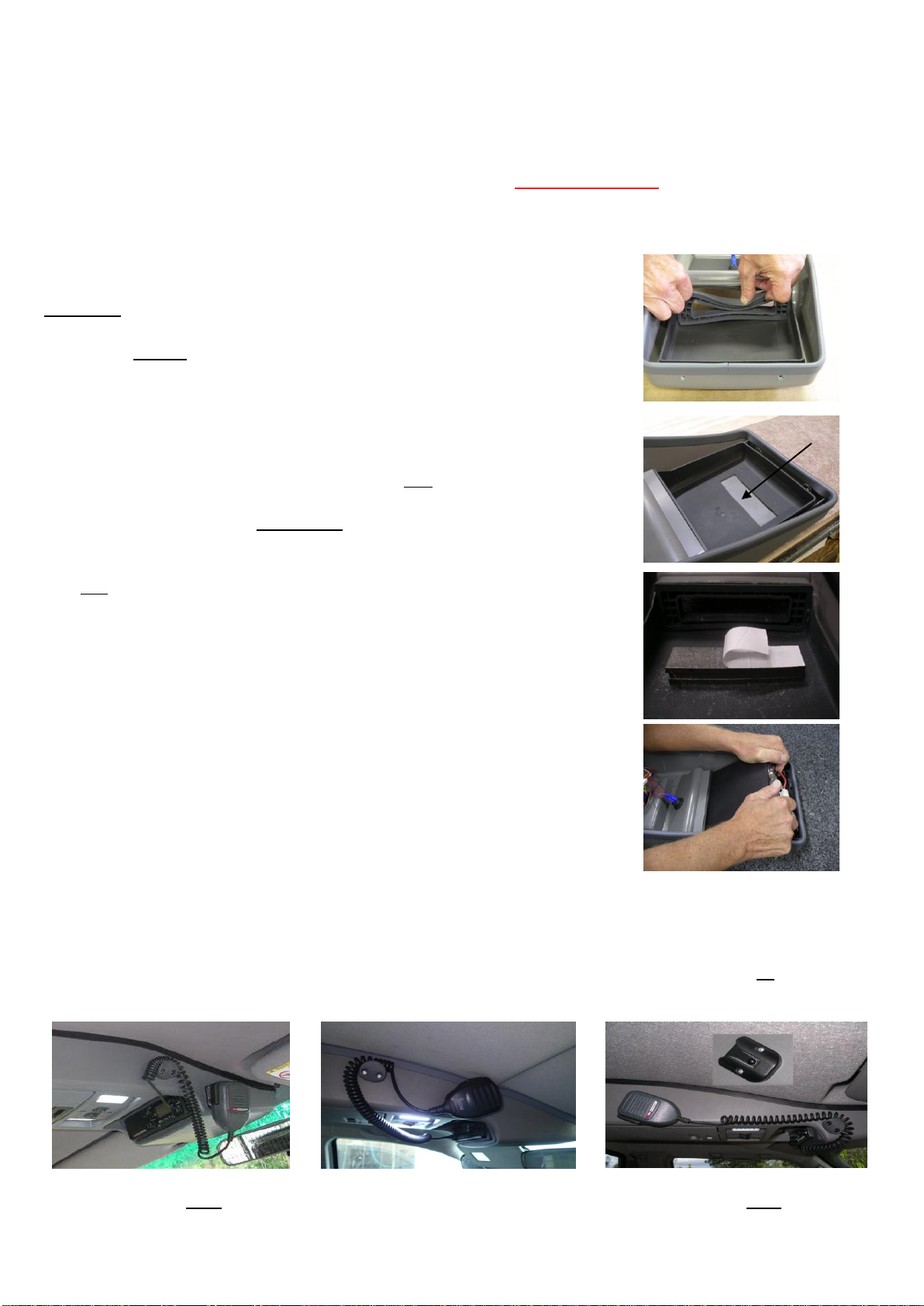
Radio Installation:
Place protective cover on work bench to avoid scratching console.
Place console on protective cover and using a sharp knife cut a 30mm x 100mm
section out of storage tray 25mm in from where rear of radio will be when
installed. Use a small amount of methylated spirits on a clean cloth to clean
exposed part of console and bottom rear of radio.
Peel one side of protective backing from foam strip supplied; apply
pressure with palm of hand to adhere foam to exposed part of console.
Peel backing off other side of foam strip and add one or more strips of foam
to suit different size radios (see chart below). This will keep radio
level with bottom of surround.
Insert radio on an angle until radio protrudes 15mm out over bottom of
tray surround or insert and straighten; lay flat onto sticky back foam and
apply firm pressure to top of radio with palm of hand for 30 seconds to
ensure good adhesion.
Sticky back foam chart:
One (1) strip- standard size radios
Two (2) strips- Icom and Uniden
Three (3) strips- GME Electrophone
Microphone and Microphone Cable Holder installation:
Install in a position that suits best, depending on vehicle and Radio model. Ensure microphone or microphone
cable and holder does not foul on sun visor when pulled down.
Microphone clip on slight angle Left hand cable outlet radios Microphone clip on acute angle
Clean here
Table of contents
Other Outback Automobile Accessories manuals


Popular Automobile Accessories manuals by other brands


ULTIMATE SPEED
ULTIMATE SPEED 279746 Assembly and Safety Advice

SSV Works
SSV Works DF-F65 manual

ULTIMATE SPEED
ULTIMATE SPEED CARBON Assembly and Safety Advice

Witter
Witter F174 Fitting instructions

WeatherTech
WeatherTech No-Drill installation instructions

TAUBENREUTHER
TAUBENREUTHER 1-336050 Installation instruction