Broad-Acre Kit Contents
Unpack your REBEL Broad-Acre kit and identify the parts as shown.
752-0005-01 1 7" terminal
804-0155-0 1 A222 Smart Antenna
9
10-1063-000 1 eDriveXD autosteering controller
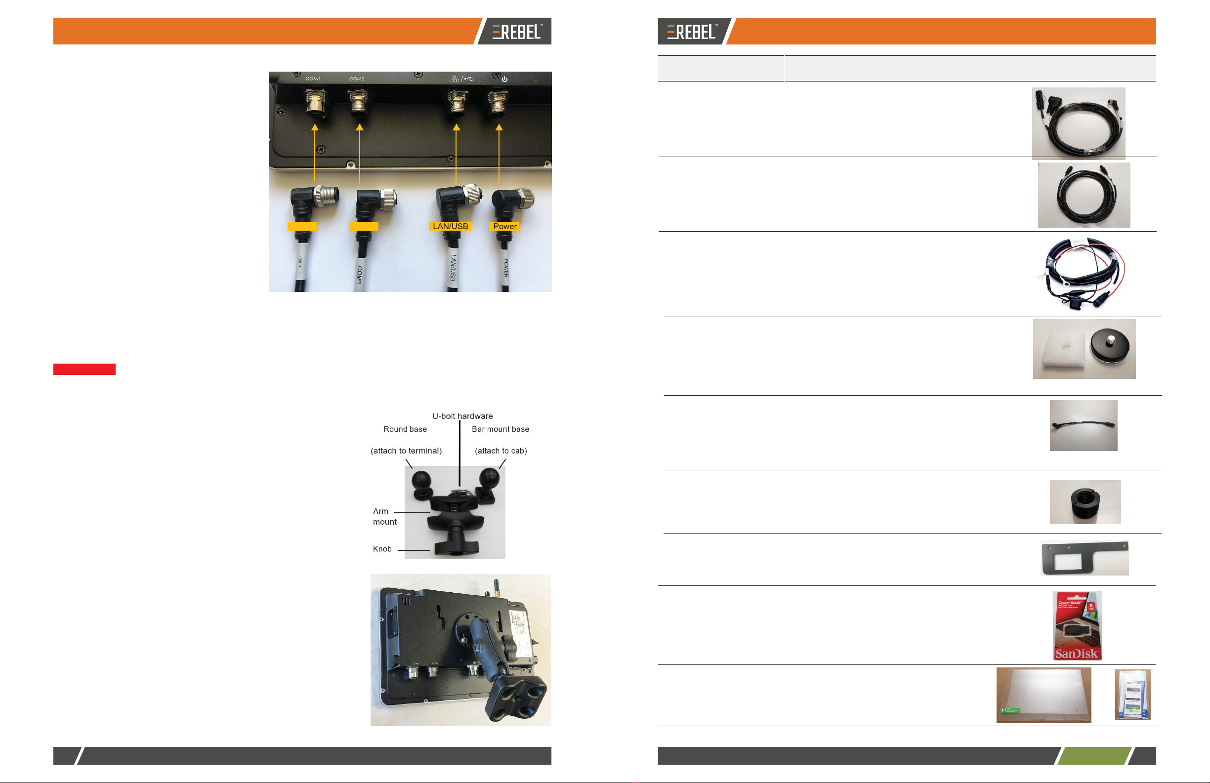
604-0015-000# 1 Terminal mounting hardware
•
Round base (attach to terminal)
•
Double socket arm mount
•
Bar mount base with U-bolts/nuts
050-0020-01 1 LAN/USB cable
Connects LAN/USB port on terminal to
eDriveXD cable
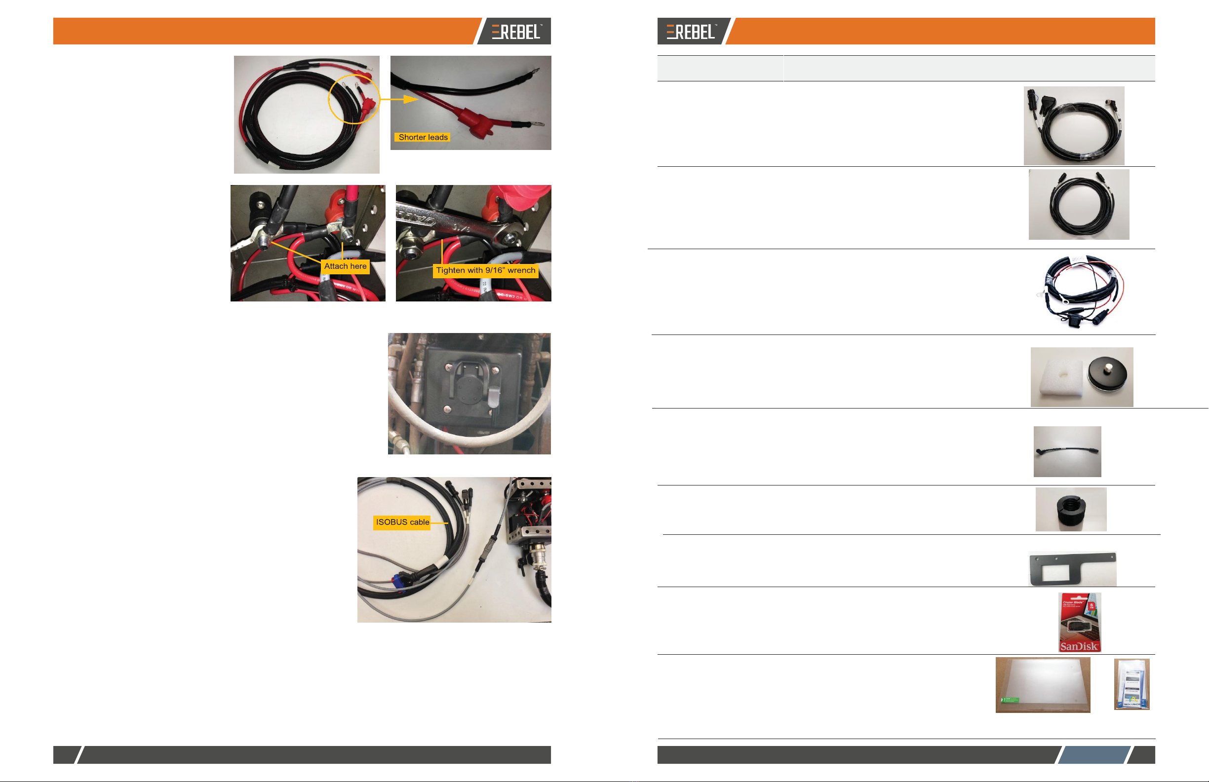
050-0022-01 1 Power cable
Connects power port on terminal to power
adapter cable
050-0043-01 1 COM1 cable
Connects COM1 port on terminal to
switchbox, lightbar/AC110 cable, and
antenna cable
d.
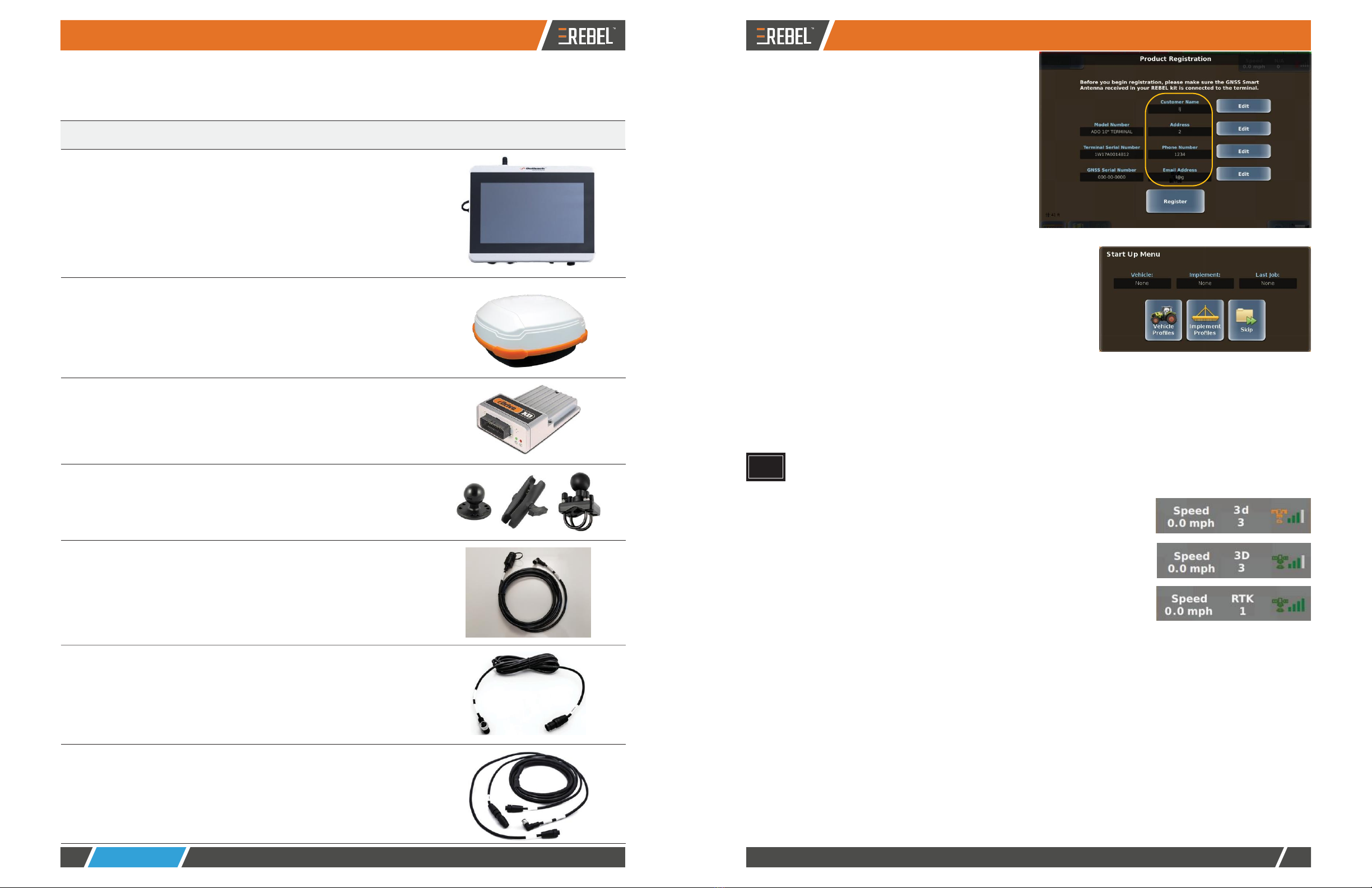
Enter your personal information. The fields
circled at right are required (upon first
displaying this screen the field labels are
red)-for each field press Edit to display a
keypad, enter a value, then press Done.
After completing all fields, the field labels turn
from red to blue.
e.
Press Register. When registration is
complete ('Registration Successful' appears
on the screen) press Complete to display
the Start Up Menu.
6.
The Start Up Menu includes read-only fields for the current
vehicle, current implement, and last job number. Whenyou
start REBEL for the first time only those buttons shown at
right appear; you will not see any 'job' buttons. You must
define a vehicle and an implement before any job
functionality is enabled.
If your system has a Task Controller subscription, the Start
Up Menu displays similar vehicle and implements fields/
buttons, but Task-related field/buttons replace the Job field/
buttons.
7.
You can press Vehicle Profiles to start adding a vehicle or press Implement Profiles to start adding an
implement; however, to learn more about adding vehicles and implements, press Skip to close the Start
Up Menu then refer to REBEL Help on your terminal-see "Using Onscreen Help" on page 28.
REBEL must have a GPS position to begin a job and provide guidance. REBEL starts acquiring a DGPS
signal (as long as the antenna has a clear view of the sky)-this may take several minutes, during which
time the vehicle can be moving and you can perform certain functions.
•
Upon achieving a GPS position, the satellite icon on the
real-time status tab (upper right of map) turns orange and '3d'
appears on the tab indicating a 3-dimensional solution.
•
Upon acquiring a DGPS position, the satellite icon turns green
and the real-time status tab displays '3D' indicating a
differentially corrected 3-dimensional solution.
•
Upon acquiring an RTK position (with optionalRTK
equipment) the tab displays 'RTK'.
Powering Down
Depending on the components of your system you may have to power down more than one component. For
example, if your REBEL system includes eDriveXC you must power down both the REBEL terminal and the
eDriveXC ECU. See "Powering Up and Registering Your Product" on page 25 for power button/switch photos of the
REBEL terminal and eDriveXC/XD ECU.
1.
Power down the REBEL terminal by pressing (and releasing) the terminal power button. REBEL will go
through its power down sequence.
2.
Power down any additional components:
•
eDriveXC/XD - turn the eDriveXC/XD ECU power switch to the off position
•
AC110 - turn the AC110 power switch to the OFF position
•
eDriveESi - this will power down when you power down eDriveXC/XD