OV _FT-0113
2
Oven Doesn’t
Perform As
Intended
Oven Doesn’t
Warm Up
GO TO PAGE 3
Screens Are Blank
GO TO PAGE 4
Screens Are
Unresponsive
GO TO PAGE 5
Slider Doesn’t
Complete Travel Or
Doesn’t Move At All
GO TO PAGE 6
Oven Doesn’t
Cook Right
GO TO PAGE 7
Red Screen
Displayed When
Starting A Cook
GO TO PAGE 8
Check Fans
Is Lit (Red Light)
GO TO PAGE 9
Abnormal Noises
From Oven
GO TO PAGE 10
An Unexpected
Screen Displays
GO TO PAGE 11
Snowy Screen
Displays
GO TO PAGE 11
No Sound From
Oven Speaker
GO TO PAGE 12
Slider Banks Into
End Of Travel
GO TO PAGE 13
“Oven Too Cold”
Or “Oven Too Hot”
Message Displays
GO TO PAGE 14
Oven Clock
Doesn’t Keep
Correct Time
GO TO PAGE 11
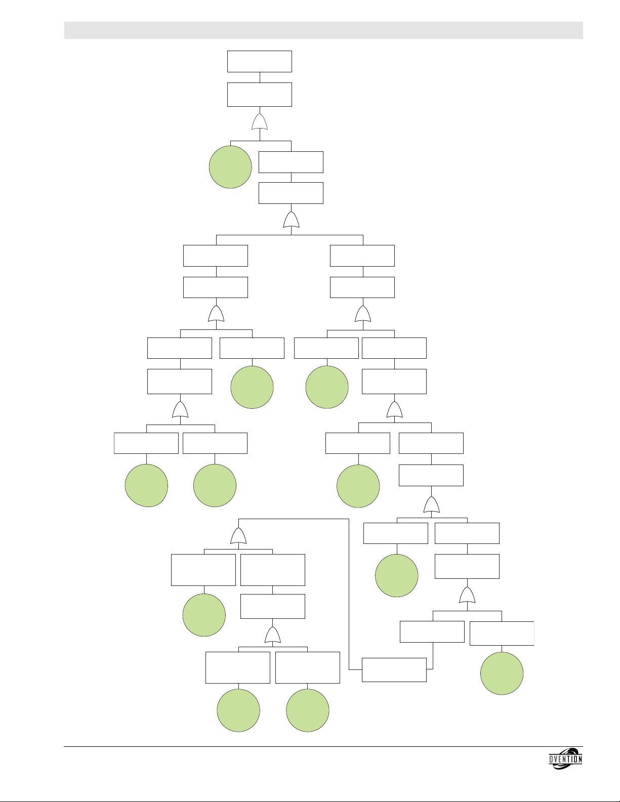
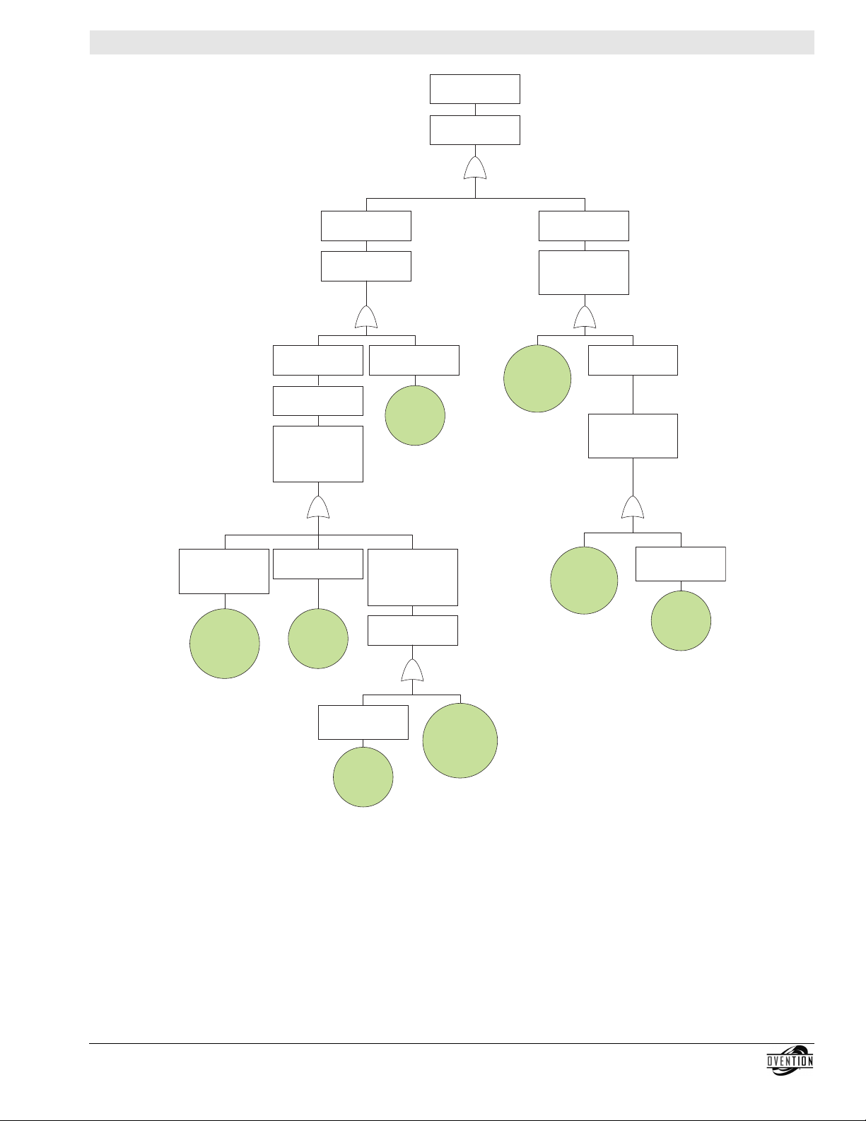
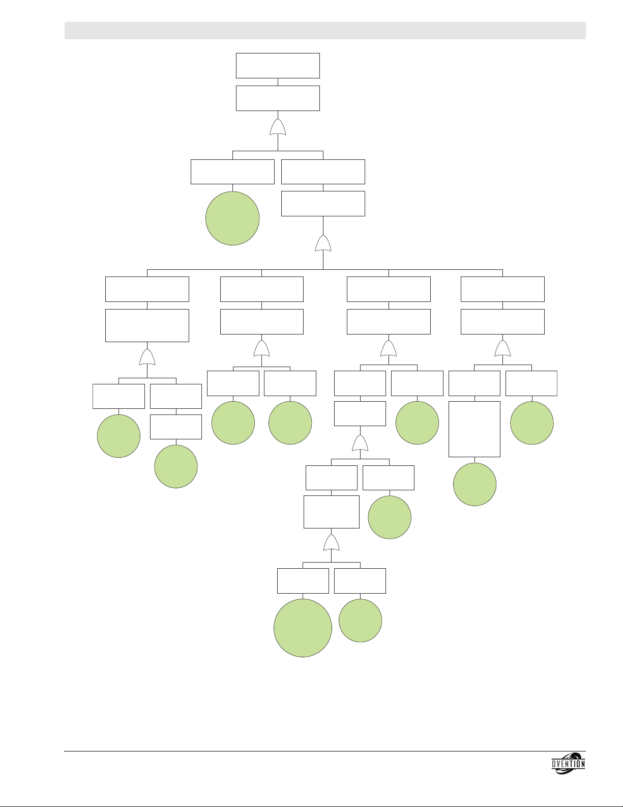
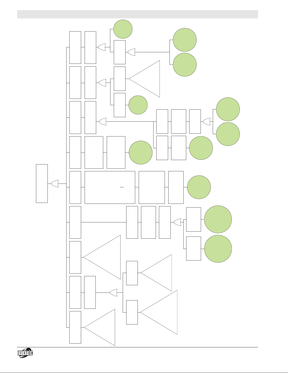
TOP LEVEL EVENT:
Oven Doesn’t Perform As Intended
Introduction
A Diagnostic Fault Tree is an excellent tool for troubleshooting
and solving problems that interrupt normal operation of a unit.
The fault tree is designed to grow from the “top level event” of
the unit not performing as intended. It is created by performing
an extensive “fault tree analysis” that considers all possible
causes of a unit failure.
Use the Diagnostic Fault Tree by starting at the Top Level Event
on this page. Review the definitions below to understand the
terminology and symbols used in the fault tree.
Definitions
Top Level Event = The highest level event in the hierarchical
fault tree.
Intermediate Event = An event in the hierarchical fault tree that
logically leads to the top level event, but is at a lower level than
the top event.
Basic Initiating Event = An event in the hierarchical fault tree
that is at the end of a branch in the tree. It is the lowest level in
a particular branch that is considered during the fault tree
analysis. The fault tree may have many branches, each with
one or more basic events.
Undeveloped Event = An event that is not further developed
either because it is of insufficient consequence or because
information is unavailable.
Symbols
The following symbols are used in this fault tree analysis. Each
symbol is shown along with its description.
Intermediate Event
The Intermediate Event symbol is used to
specify a failure event that occurs due to one or
more causes acting through logic gates below it
in the fault tree.
Basic Initiating Event
The Basic Initiating Event symbol is used to specify
a failure event that does not require any further
development. In other words, it is a “leaf” on the
fault tree and has no events or gates below it in the
tree.
“Or” Logic Gate
The Or logic gate symbol is used to show that the
output fault (everything below) will occur only if one or
more of the input faults (everything above) take place.
Transfer
This symbol is used to modularize a fault tree. For
example, if there is a sequence of events that
occurs in more than one place in the fault tree, then
it can be removed and placed into a separate sub-
tree and just referenced by the main fault tree.