Form No. OVMM-0912 3
IMPORTANT SAFETY INFORMATION
EXPLOSION HAZARD: Do not store or use gasoline or
other flammable vapors or liquids in the vicinity of this or
any other appliance.
This oven is designed specifically to heat or cook—NOT
for industrial or laboratory use.
Use Main Disconnect Switch on left side of oven to turn off
oven in emergency.
Make sure all operators have been instructed on the safe
and proper use of the unit.
This unit is not intended for use by children or persons
with reduced physical, sensory, or mental capabilities.
Ensure proper supervision of children and keep them away
from the unit.
This unit has no “user-serviceable” parts. If service is
required on this unit, contact an Authorized Ovention
Service Agent or contact the Ovention Hotshot Hotline at
855-298-6836.
BURN HAZARD:
• Some exterior surfaces on unit will get hot. Avoid
unnecessary contact with unit.
• Pan/tray will be very hot upon removal—use oven mitt,
pan gripper, or other utensil to remove.
Do not disconnect unit from power supply immediately
after use. Internal fans must cool oven to avoid damage to
electrical components.
Locate unit at proper counter height in an area that is
convenient for use. Location should be level to prevent
unit or its contents from falling accidentally and strong
enough to support the weight of the unit and contents.
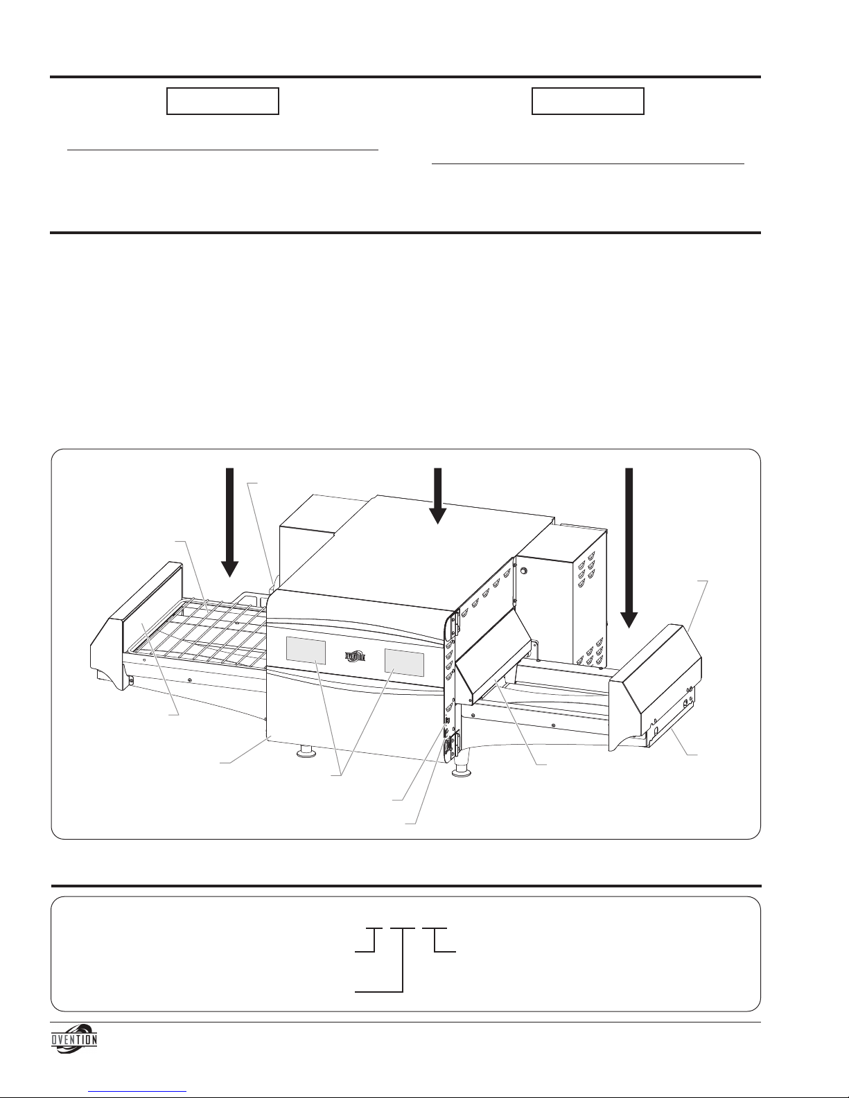
DO NOT lift unit by platforms on each side of oven
chamber. Platforms are not designed to support weight of
unit. Lift from underneath oven chamber only.
Do not move or relocate unit for cleaning. Unit is bulky and
heavy.
Do not place anything on top of unit; doing so may subject
personnel to injury or could damage unit.
Do not heat sealed containers or products such as whole
eggs in oven. These items may explode.
Use caution and be aware of pinch points when slider
assembly is moving.
Do not store any materials or items inside oven chamber
when not in use.
Improper cleaning of oven could damage catalyst and will
void unit warranty.
Allow a minimum clearance of 1″ (25 mm) along the sides
and rear of unit for proper ventilation. Do not block or
cover any cabinet venting.
ELECTRIC SHOC HAZARD:
• Plug unit into a properly grounded electrical receptacle
of the correct voltage, size, and plug configuration. If
plug and receptacle do not match, contact a qualified
electrician to determine and install proper voltage and
size electrical receptacle.
• Unit must be grounded properly. Failure to ground unit
properly could result in serious personal injury or
death.
• Turn off Standby switch, allow unit to cool, and turn
OFF Main Disconnect switch before performing any
cleaning, adjustments, or maintenance.
• DO NOT submerge or saturate with water. Unit is not
waterproof. Do not operate if unit has been submerged
or saturated with water.
• Unit is not weatherproof. Locate unit indoors where
ambient air temperature is a minimum of 70°F (21°C).
• Do not steam clean or use excessive water on unit.
• This unit is not “jet-proof” construction. Do not use jet-
clean spray to clean this unit.
• Do not clean unit when it is energized or hot.
• Do not clean unit with metal scouring pads. Metal
pieces can break off pad and touch electrical
components, creating risk of electric shock.
• Do not pull unit by power cord.
• eep power cord away from heated surfaces.
• Do not allow power cord to hang over edge of counter.
• Discontinue use if power cord is frayed or worn.
• Do not attempt to repair or replace a damaged power
cord. Cord must be replaced by an Authorized Ovention
Service Agent or a person with similar qualifications.
• This unit must be serviced by qualified personnel only.
Service by unqualified personnel may lead to electric
shock or burn.
• Use only Genuine Ovention Replacement Parts when
service is required. Failure to use Genuine Ovention
Replacement Parts will void all warranties and may
subject operators of the equipment to hazardous
electrical voltage, resulting in electrical shock or burn.
Genuine Ovention Replacement Parts are specified to
operate safely in the environments in which they are
used. Some aftermarket or generic replacement parts
do not have the characteristics that will allow them to
operate safely in Ovention equipment.
FIRE HAZARD:
• Do not install unit on or around combustible surfaces.
Discoloration or combustion could occur. Unit must be
installed in non-combustible surroundings only.
• Do not use an extension cord. If power cord is too short,
contact a qualified electrician to determine and install
proper voltage and size electrical receptacle near unit.
Install unit in accordance with installation instructions in
this manual.
Read the following important safety information before using this equipment to avoid
serious injury or death and to avoid damage to equipment or property.