Overlander VSRmini User manual

VSRmini
OPERATING MANUAL
AC BALANCE CHARGER/DISCHARGER
for LiPo/LiFe/LiHV/LiIon/NiMH/NiCd/Pb Batteries
Please read and understand this entire operating
manual before using.

PLEASE FOLLOW THE FOLLOWING DIRECTIONS TO ENSURE
SAFE AND SUCCESSFUL USE OF THE OVERLANDER VSRmini
AC BALANCE CHARGER.
WARNING : Read and familiarise yourself with the instruction manual before operating the
charger, seek advice from other charger users or Overlander if you are unsure of any
procedures.
This charger automatically balances Lithium batteries in charge/discharge and storage mode.
When charging Lithium batteries, always ensure that the balance connector is connected FIRST
in the sequence. This charger will not start a charge/discharge or storage charge if the balance
lead is not connected. This charger will NOT charge batteries without a balance lead.
WARNING : This charger is not a domestic appliance, it should be only used and positioned in
the correct environment.
Due to the power volatility of Lithium batteries it should be positioned on a fireproof base at least
1.5 metres from any flammable materials
WARNING : • Never charge in a domestic setting
• Never leave the charger unattended
• Never exceed maximum battery charge rate
• Never charge a standard LiPo battery on LiHV setting
• Never charge non-approved or non EU compliant batteries
• Never charge in the wrong mode
• Never charge near flammable material
• Never charge near any items of value. Overlander or its retailers take no
responsibility for 3rd party items that may be damaged by incorrect use.
OVERLANDER VSRmini
CHARGER USER WARNINGS

Contents
1. Features .........................................................................................................1
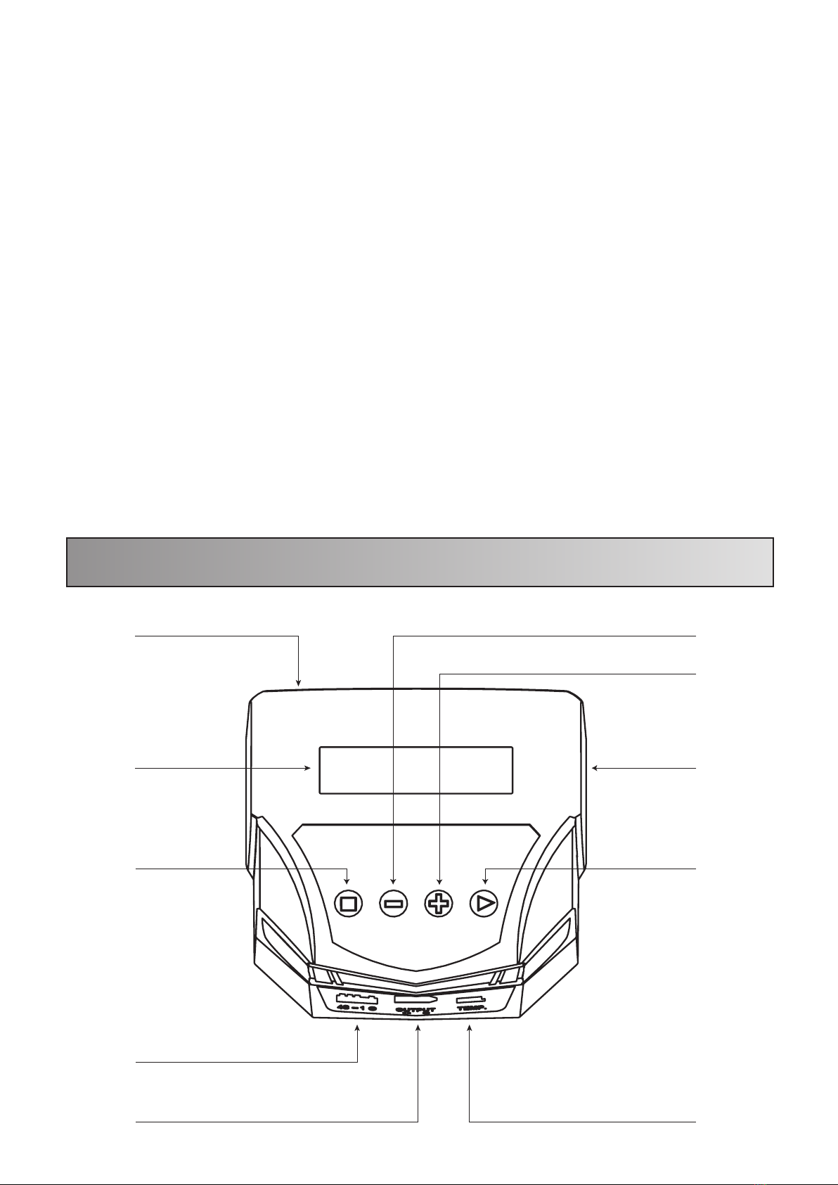
2. Exterior of the unit ........................................................................................2
3. Warnings and safety notes ..........................................................................3
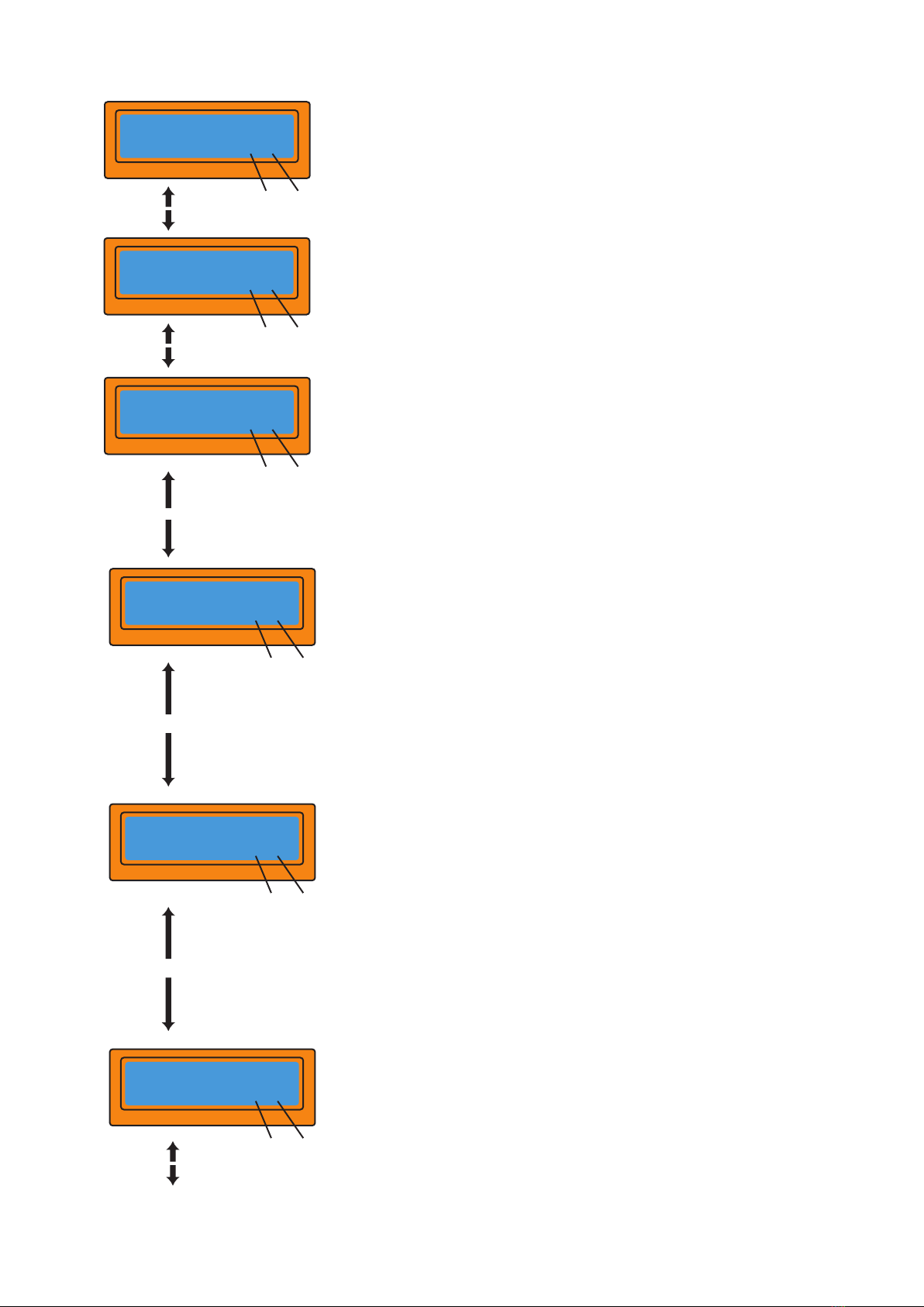
4. Program flow chart .......................................................................................5
5. Parameter set up (User settings) ..................................................................6
6. Lithium battery (LiPo/LiFe/LiHV/LiIon) programs .......................................8
6.1 Charging ....................................................................................................8
6.2 Balance mode ............................................................................................9
6.3 'FAST' charging .......................................................................................10
6.4 'STORAGE' mode ....................................................................................10
6.5 Discharging .............................................................................................11
6.6 Voltage balancing and monitoring during discharge .................................11
7. NiMH/NiCd battery programs ......................................................................12
7.1 Charging ..................................................................................................12
7.2 Discharging ..............................................................................................12
7.3 ‘CYCLE’ mode ..........................................................................................13
8. Pb (lead acid) battery program ..................................................................13
8.1 Charging Pb battery ................................................................................13
8.2 Discharging Pb battery ............................................................................14
9. Battery internal resistance testing system ...............................................14
10. Save Data Program ...................................................................................15
11. Load Data Program ...................................................................................16
12. Program information .................................................................................16
13. Warning and error messages ...................................................................17
14. Specifications ............................................................................................19
15. Warranty and service ................................................................................19
PLEASE FOLLOW THE FOLLOWING DIRECTIONS TO ENSURE
SAFE AND SUCCESSFUL USE OF THE OVERLANDER VSRmini
AC BALANCE CHARGER.
WARNING : Read and familiarise yourself with the instruction manual before operating the
charger, seek advice from other charger users or Overlander if you are unsure of any
procedures.
This charger automatically balances Lithium batteries in charge/discharge and storage mode.
When charging Lithium batteries, always ensure that the balance connector is connected FIRST
in the sequence. This charger will not start a charge/discharge or storage charge if the balance
lead is not connected. This charger will NOT charge batteries without a balance lead.
WARNING : This charger is not a domestic appliance, it should be only used and positioned in
the correct environment.
Due to the power volatility of Lithium batteries it should be positioned on a fireproof base at least
1.5 metres from any flammable materials
WARNING : • Never charge in a domestic setting
• Never leave the charger unattended
• Never exceed maximum battery charge rate
• Never charge a standard LiPo battery on LiHV setting
• Never charge non-approved or non EU compliant batteries
• Never charge in the wrong mode
• Never charge near flammable material
• Never charge near any items of value. Overlander or its retailers take no
responsibility for 3rd party items that may be damaged by incorrect use.

1. Features
Optimised operating software
The VSRmini has an ‘AUTO’ function that sets the current automatically when charging or
discharging, preventing the battery from over-charging, which could lead to a fire or
explosion. These specifications can also be set by the user. The built in balance charge
port makes it convenient for use with Lithium batteries. This charger also comes with XT60
to Deans conversion lead for Deans type batteries.
High-power and high-performance circuit
The max output is 80W. The max charge is 7A. The max discharge current is 1A. It can
charge/discharge NiMH/NiCd battery with up to 15 cells, and Lithium batteries with 6 cells.
The CPU operating program works under such power as the charger is fitted with a highly
efficient cooling system.
Individual voltage balancer for Lithium batteries inside
The charger has a special internal function for Lithium battery voltage balancing. You do
not require an additional balancer to balance the voltage when charging Lithium batteries
(LiPo/LiFe/LiIon).
Balance individual cells
The charger also monitors and balances the individual cells of a Lithium battery pack
during the charging/discharging process. If the voltage of any cell varies abnormally, the
process will be stopped automatically and an error message will appear on the screen.
Accept various types of Lithium battery
This charger can be used with a wide range of batteries with different chemistries (LiPo,
LiHV, LiFe, LiIon, NiMH, NiCd and Pb). Choose the corresponding program, setting the
parameters on the base of the battery type and specifications, before you start to
charge/discharge.
Lithium battery 'Fast' and 'Storage' mode
The “Fast” charge reduces the charging time of Lithium batteries. The “Storage” mode
controls the nominal voltage of the battery to make it suitable for long-term storage.
NiMH/NiCd cyclic charging/discharging
With this charger you can perform 1-4 cycles of charge>discharge or discharge>charge
continually for battery refreshing and balancing.
Data store/load
This charger can store a maximum of 5 different batteries data. These settings can then be
called out at any time and the process can be executed without having to reselect all of the
correct settings.
-1 -

2. Exterior of the unit
Maximum safety
- Delta-peak Sensitivity: when the battery voltage of NiMH/NiCd batteries reaches the
highest point and begins to drop, the charging process with automatically stop.
- Capacity Limit: the charging process will terminate automatically when the maximum
capacity value that is set is reached.
- Temperature Limit: the temperature of the battery will rise during the charging process
due to internal chemical reactions. In order to prevent overheating the charging process
will forcibly end if the temperature limit that is set is reached. This function is only available
by connecting an optional temperature probe, which is not included in the package. Avail-
able from Overlander (SKU: 2598).
- Charge Time Limit: charging will stop when charge time limit set is reached to avoid any
possible over-charging/over-discharging.
- Input Current Check: to prevent the battery from being damaged by the input current,
the charger monitors the voltage and ends the process automatically when the voltage
drops below the lowest limit.
- Automatic cooling fan: the automatic electric cooling fan controls the internal tempera-
ture of the charger to prevent over-heating.
-2 -
AC Input (100-240V)
LCD Display
Stop/Main Menu
Balance Lead Port
Charging Lead Port Temp. Sensor Port
Start/Enter
Cooling Fan
Increase INC(+)
Decrease DEC(-)

3. Warnings and Safety notes
IMPORTANT! Please follow these instructions for maximum safety, otherwise
the charger and/or battery could be badly damaged and may lead to fire,
explosion, injury or property loss.
- Never leave the charger unattended when it is connected to its power supply.
-If any malfunction is observed, terminate the process immediately and refer to the manual.
- Keep the charger away from dust, damp, humidity, rain, heat, direct sunshine and vibration.
- The circuit of the unit is designed to be powered by 100-240V AC only.
Voltage level: 1.2V/cell
Recommended fast charge current: 1C~2C depends on
the performance of cell discharge voltage cut off level
0.85V/cell (NiCd), 1.0V/cell (NiMH)
Voltage level:3.6V/cell
Max. charge voltage: 4.1V/cell
Recommended fast charge current: 1C or less
Min. discharge voltage cut off level: 2.5V/cell or higher
Voltage level: 3.7V/cell
Max. charge voltage: 4.2V/cell
Recommended fast charge current: 1C or less
Min. discharge voltage cut off level: 3.0V/cell or higher
Voltage level: 3.8V/cell
Max. charge voltage: 4.3V / 4.35V / 4.4V/cell
Recommended fast charge current: 1C or less
Min. discharge voltage cut off level: 3.0V/cell
Ensure maximum charge voltage is set. This would
usually be 4.35V but please check instructions with the
LiHV battery. Never charge standard LiPo battery on
LiHV setting.
Voltage level:3.3V/cell
Max. charge voltage:3.6V/cell
Recommended fast charge current: 4C or less
Discharge voltage cut off level:2.0V/cell or higher
Voltage level:2.0V/cell (Lead-acid)
Max. charge voltage:2.46V/cell
Recommended fast charge current:0.4C or less
Min. discharge voltage cut off level:1.50V/cell or higher
NiCd / NiMH
LiIon
LiPo
LiHV
LiFe
Pb
-3 -

-Do not place the charger on flammable or conductive surfaces when
charging/discharging. Never use the charger on car seats, carpets or similar surfaces. Do
not operate near items of value or anything with the potential to catch fire or explode.
- Ensure the unit remains well ventilated by making sure that all ventilation holes are
unblocked and uncovered.
-Set the parameters correctly, otherwise the battery could be severely damaged. Lithium
batteries especially can cause a fire or explosion when over-charged. Always check that
the selected chemistry is correct. Never charge standard LiPo batteries on LiHV setting.
- To avoid short-circuits between the wires, always connect the charge cable to the unit first
and then to the battery. Reverse the sequence when disconnecting.
-Always check the capacity and voltage of a Lithium battery pack before starting
any process. It may be a mixture of parallel and series connections. In parallel, individual
cell capacity multiplied by the cell count is the pack capacity, but the voltage remains the
same. It is important to enter the correct parameters in order to prevent the risk of
fire/explosions.
- When setting the discharge parameter, it must be according to the residual capacity of
the pack to lower the voltage of the battery. To avoid over-discharging, please set the
nominal discharge correctly. The voltage of Lithium batteries must not be discharged lower
than the minimum voltage because this can lead to a rapid loss of capacity or a total
failure. Generally there is no need to discharge a Lithium battery.
- Some batteries have a ‘memory’, in that if the capacity is only partially used the battery
will ‘remember’ to just use the same amount in the future:
- NiMH and NiCd batteries do have a memory function, but usually run complete cycles.
This means they are fully charged and then completely used.
-Lithium batteries prefer a partial rather than full discharge. Frequent full discharge
should be avoided if possible. Instead you should charge the battery more often or
keep the nominal voltage.
-This charger is not a domestic appliance. It should be used and positioned in the correct
environment and should not be used in a domestic setting. Due to the power and volatility
of Lithium batteries the charger and battery should be placed on a fireproof base at least
1.5 metres from any flammable materials. Overlander or its retailers accept no liability for
losses to 3rd party items caused by failure to follow these instructions.
-By purchasing this product the user assumes all risks associated with its use. If you do
not agree with this clause then please return the item immediately before use.
-Failure to comply with these instructions will result in all warranties being deemed void.
-4 -

4. Program ow chart
PROGRAM SELECT
LIXX BATT
PROGRAM SELECT
NiMH BATT
PROGRAM SELECT
NiCd BATT
PROGRAM SELECT
Pb BATT
PROGRAM SELECT
SAVE DATA
PROGRAM SELECT
LOAD DATA
USER SET
PROGRAM
NiMH CHARGE
‘Aut’ / ‘Man’
NiCD CHARGE
‘Aut’ / ‘Man’
LIXX CHARGE
Pb CHARGE Pb DISCHARGE
LOAD DATA
SAVE DATA
LIXX BALANCE
LIXX V.TYPE LiIo / LiPo / LiFe /
LiHV CHK Time NiMH Sensitivity
D.Peak NiCD Sensitivity
D.Peak
Temp Cut-Off
USB Enable
Waste Time
CHG > DCHG
Safety Timer
Input Power Low
Cut-Off
Capacity Cut-Off
Key Beep
Buzzer
NiMH DISCHARGE
NiCD DISCHARGE
NiMH CYCLE
NiCD CYCLE
LIXX DISCHARGE
LIXX FAST CHG LIXX STORAGE
Batt type
stop
Start
Enter INC>
<DEC
INC>
<DEC
INC>
<DEC
INC>
<DEC
INC>
<DEC
INC>
<DEC
INC>
<DEC
INC>
<DEC
INC> <DEC
INC> <DEC
INC>
<DEC
INC>
<DEC
INC>
<DEC
INC>
<DEC
INC>
<DEC
INC>
<DEC
INC>
<DEC
Start
Enter
Start
Enter
Start
Enter
Start
Enter
Start
Enter
Start
Enter
Batt type
stop
Batt type
stop
Batt type
stop
Batt type
stop
Batt type
stop
Batt type
stop
-5 -
INC> <DEC
TEST LiXX INTERNAL
RESISTANCE
Measuring IR
WAIT PLEASE...
1:026 050 044 mΩ
4:039 042 044 mΩ
Battery Pack IR
231Ω
INC>
<DEC
INC>
<DEC
Start
Enter

5. Parameter set-up (User settings)
The charger will automatically be operated with the default user settings when it is
connected to a 12V battery for the first time. The screen displays the following
information in sequence and the user can change the value of the parameters on
each screen. If you want to alter the parameter value in the program, press Start/
Enter to make it blink then change the value with INC or DEC. The value will then be
stored by pressing Start/Enter.
The screen displays the nominal voltage of the
Lithium battery. There are four kinds of Lithium
battery; LiFe (3.3V), LiIon (3.6V), LiPo (3.7V) or
LiHV (3.8V). It is very important that you check
the battery carefully to ensure it is set up
correctly. If the incorrect values are selected the
battery could ignite or explode during the
charging process.
The charger will recognise the cell count of the
battery automatically at the beginning of the
charge or discharge process to reduce the
chances of incorrect settings being selected by
the user. However, a deeply discharged battery
can be perceived incorrectly, so it is important to
check that all of the information is correct. To
prevent any errors, you can set the time term to
verify the cell count detected by the processor.
Normally 10 minutes is enough to perceive the
cell count correctly. For a battery of a larger
capacity, you may need to extend the time term.
However, be careful not to set the time term for
too long for a battery of a smaller capacity, as the
charge or discharge process can be finished
within the time term with the wrong cell count,
which could then result in over-charging the
battery.
If the processor recognises the cell count
incorrectly at the beginning of the charge or
discharge process, you may extend the time.
Otherwise, it is recommended that you use the
default value.
Display
LiPo/LiIo/LiFe
CHK time 10min
< Dec Inc >
< Dec Inc >
Display
LiFe
V.Type 3.3v
< Dec Inc >
- +
-6 -

This shows the trigger voltage for automatic
charge termination of NiMH and NiCd battery.
The effective value ranges from 5 to 20mV per
cell. If the trigger voltage is set higher, there is a
danger of overcharging the battery; if it is set
lower, there is a possibility of premature
termination. Please refer to the technical
specifications of the battery. (NiCd default:
12mV, NiMH default: 7mV)
This program sets the maximum charge capacity
that will be supplied to the battery during charge.
If the delta-peak voltage is not detected, or if the
safety timer is not working for any reason, this
feature will automatically stop the process when
the battery reaches the selected capacity value.
The 3-pin port at the left side is a temperature
port. You can use a temperature probe to contact
the surface of a battery. You can set the maximum
temperature at which the charger will allow the
battery to reach during charging. Once a battery
reaches this temperature during charge, the
process will be terminated to protect the battery.
This shows a battery that is on a cyclic process of
charge and discharge. These can often become
warm after the charge or discharge period. This
program can insert a time delay to occur after
each charge and discharge process to allow the
battery adequate time to cool down before being
subjected to the next process. The value ranges
from 1 to 60 minutes.
When you start a charge process, the integral
safety timer automatically starts running at the
same time. This is programmed to prevent
overcharge if the battery proves to be faulty and
the termination circuit cannot detect if the battery
is full. The value for the safety timer should be
generous enough to allow a full charge of the
battery.
< Dec Inc >
< Dec Inc >
< Dec Inc >
< Dec Inc >
< Dec Inc >
< Dec Inc >
Display
NiMH sensitivity
D.Peak Default
< Dec Inc >
- +
Display
Capacity Cutoff
ON 5000mAh
< Dec Inc >
- +
Display
NiCD sensitivity
D.Peak Default
< Dec Inc >
- +
Display
Safety Temp
Temp Cut-off 80C
< Dec Inc >
- +
Display
Waste Time
CHG/DCHG 5min
< Dec Inc >
- +
Display
Safety Timer
ON 120min
< Dec Inc >
- +
-7 -

6. Lithium Battery Programs (LiIon/LiPo/LiFe/LiHV)
The beep sounds every time a button is pressed
to confirm your action. Beeps or melodies may be
sounded at various times during operation to alert
the user of different mode changes. You can turn
these sounds on and off.
This program monitors the input voltage to the
battery. If the voltage drops below the value you
set, the operation will be forcibly terminated to
protect the battery.
On this screen the top line displays the battery
type and the second line shows the charge
current and the voltage of the battery pack.
After selecting the correct current and voltage,
hold Start/Enter down for 3 seconds to start the
process.
(Charge current: 0.1~6.0A; Voltage: 2-4S)
These programs are only suitable for charging and discharging Lithium batteries
with a nominal voltage of 3.3V (LiFe), 3.6V (LiIon), 3.7V (LiPo) and 3.8V (LiHV) per
cell. These various battery types will all have different charge voltages (CV) and
charge currents (CC). The charge current input varies according to the battery
capacity and performance, so it is very important that you select the correct
battery type before starting any process.
The final voltage of the charge process is also very important; it should be precisely
matched with the correct voltage of the battery. Per cell these voltages are: 3.6V for
LiFe, 4.1V for LiIon or 4.2V for LiPo. The option for peak cell voltage of 4.4V for
LiHV should only be used if the battery instructions specifically allow this, to prevent
danger of overcharging. Otherwise select either 4.3V or 4.35V for LiHV. The charge
current and nominal voltage, as per the cell count set on the charge program, must
always be correct for the battery being charged.
If you wish to alter the default parameter value in the program, press Start/ Enter to
make the value blink then change the value with INC or DEC. The value will be
stored by pressing Start/Enter once.
6.1 Charging Lithium Batteries
< Dec Inc >
Display
Key Beep ON
Buzzer ON
< Dec Inc >
- +
Display
Input Power Low
Cutoff 10.0V
< Dec Inc >
- +
<Batt type Start > 3 seconds
stop Enter
Display
LiPo Charge
2.0A 11.1v (3S)
< Dec Inc >
- +
< Dec Inc >
- +
-8 -

This shows the number of cells within the battery
pack. 'R:' is the number of cells found by the
charger, and 'S:' is the number of cells selected
by the user on the previous screen. If both
numbers are identical you can start charging by
press Start/Enter. If not, press Batt Type/Stop to
go back to previous screen to modify any
incorrect information that may have been input by
the user.
On this screen the first value on the second line is
the charge current and the second value is the
voltage of the battery pack.
After selecting the correct values for the current
and voltage hold Start/Enter for 3 seconds to
start the process.
(Charge current: 0.1~6.0A; Voltage: 2-4S)
This shows the number of cells within the battery
pack. 'R:' is the number of cells found by the
charger, and 'S:' is the number of cells selected
by the user on the previous screen. If both
numbers are identical you can start charging by
pressing Start/Enter. If not, press Batt Type/
Stop to go back to previous screen to modify any
incorrect information that may have been input by
the user.
This screen shows the present position of the
balance charging process. To stop charging press
Batt Type/Stop key once.
This screen shows the present position of the
charging process. To stop charging press Batt
Type/Stop once.
6.2 Charging Lithium batteries in ‘BALANCE’ mode
This mode is used to balance the individual cells of a Lithium battery. The pack being
charged should be connected to the suitable balance port at the right side of the
charger as well as to the output plug of the charger.
In this mode, the charging process will be different from the ordinary charging mode.
The internal processor of the charger will monitor the voltages of each cell within the
pack and control the charging current that is feeding to each cell to normalise the
voltage.
Start
Enter
Display
R:3SER S:3SER
CONFIRM (ENTER)
< Dec Inc >
- +
Display
R:3SER S:3SER
CONFIRM (ENTER)
Display
Li3S 2.0A 12.59V
CHG 022:42 00682
Number
of cells Charging
time Charge
rate Battery
voltage Charged
capacity
Display
Li3S 2.0A 12.59V
CHG 022:42 00682
Number
of cells Charging
time Charge
rate Battery
voltage Charged
capacity
<Batt type Start > 3 seconds
stop Enter
Display
LiPo Balance
2.0A 11.1v (3S)
< Dec Inc >
- +
< Dec Inc >
- +
-9 -

You can set up the charging current and the
voltage of the battery pack which is being
charged. Press Start/Enter to bring up the
voltage confirmation screen. If the voltage and
current parameters are correct, press Start/
Enter again to start the charging process.
This screen shows the present position of the
‘FAST’ charging process. To stop charging press
Batt Type/Stop once.
6.3 'FAST' charging Lithium batteries
The charging current decreases as the process reaches its end, meaning that the
charge process will slow down. To speed up the charging process, the ‘FAST’
charging program eliminates certain aspects of the cut-off voltage process. The
charging capacity may be slightly less than normal but the process time will be
reduced.
6.4 'STORAGE' control for Lithium batteries
This mode is for charging or discharging Lithium batteries that are going to be stored
for any length of time. The program will charge/discharge the battery to the best
voltage for storing, depending on the current voltage of the battery. Voltages per cell
differ depending on the battery chemistry: 3.3V for LiFe, 3.75V for LiIon, 3.85V for
LiPo, and 3.85 for LiHV. If the voltage of the battery in its current state is over the
ideal voltage level for storage, the program will start to discharge.
Display
Li3S 2.0A 12.59V
FAS 022:42 00682
Number
of cells Charging
time Charge
rate Battery
voltage Charged
capacity
<Batt type Start > 3 seconds
stop Enter
Display
LiPo Fast CHG
2.0A 11.1v (3S)
< Dec Inc >
- +
< Dec Inc >
- +
Here you can input the current and the voltage of
the battery pack to be charged. The current will
be used to either charge or discharge the battery
in order for it to reach the ideal 'STORAGE' level
voltage.
This screen shows the present position of the
‘STORAGE’ process. To stop charging press Batt
Type/Stop once.
Display
Li3S 2.0A 12.59V
STO 022:42 00682
Number
of cells Charging
time Charge
rate Battery
voltage Charged
capacity
<Batt type Start > 3 seconds
stop Enter
Display
LiPo Storage
2.0A 11.1v (3S)
< Dec Inc >
- +
< Dec Inc >
- +
-10 -

The discharge current (shown on the left side of
the screen) should not exceed 1C and the final
voltage on the right should not be under the
voltage level that is recommended by the battery
manufacturer to avoid deep discharging. To start
the discharge process, hold Start/ Enter key for 3
seconds.
This screen shows the present position of the
discharging process. To stop discharging press
Batt Type/Stop once.
This screen will appear if the processor finds that
the voltage of one of the cells in the Lithium
battery pack is too low.
6.5 Discharging Lithium batteries
6.6 Voltage balancing and monitoring during discharge
The processor monitors the voltage of the individual cells of the Lithium battery pack
during 'storage-mode' and 'discharge'. It tries to normalise the voltages of each cell
so they are all equal. For this feature, the individual plug of the battery pack should
be connected to the individual port of the charger.
If the voltage of one or more cells appears abnormal, the charger will automatically
terminate the process and an error message will show on the screen. The
occurrence of this indicates that the battery pack contains a damaged cell, or that
the battery has not been connected to the charger correctly. To find out which cell
within the pack is damaged, press INC while the error message is on the screen.
Display
Li3S 0.4A 12.59V
DSC 022:42 00682
Number
of cells Charging
time Discharge
rate Battery
voltage discharged
capacity
<Batt type Start > 3 seconds
stop Enter
Display
LiPo Discharge
1.0A 11.1v (3S)
< Dec Inc >
- +
< Dec Inc >
- +
Display
BATTERY VOL ERR
CELL LOW VOL
In this example, the 4th cell is faulty. In the case
that the battery is not connected to the charger
correctly, all of the values will show zero.
Display
1:3.77 2:3.72V
3:2.56 4:0.00V
-11 -

7. NiMH/NiCd battery programs
This program charges the battery using the
charge current set by the user. In 'Aut' mode, you
must set the charge current limit to prevent the
charger feeding too much current into the battery,
which could cause damage. In 'Man' mode, the
battery will be charged with the charge current set
by the user. You can change the mode by
pressing INC and DEC button simultaneously
when the current field is blinking.
The discharge current is shown on the left and the
voltage of the pack on the right. The discharge
current ranges from 0.1A to 1.0A and the final
voltage ranges from 0.1V to 25.0V). You can alter
the parameters by pressing Start/Enter. Once
the correct values have been input, press
Start/Enter again to store the values. To start the
process, hold Start/Enter for 3 seconds.
This screen shows the present position of the
discharging process. To stop discharging press
Batt Type/Stop once.
This screen shows the present position of the
charging process. To stop charging press Batt
Type/Stop once.
7.1 Charging NiCd/NiMH batteries
7.2 Discharging NiCd/NiMH batteries
These programs are only for charging or discharging NiMH (Nickel-Metal-Hydride)
or NiCd (Nickel-Cadmium) batteries. If you wish to alter the default parameter value
in the program, press Start/ Enter to make the value blink then change the value
with INC or DEC. The value will be stored by pressing Start/Enter once.
Display
NiMH 2.0A 7.42V
CHG 022:45 00890
Battery Type Charging
time Charge
rate Battery
voltage Charged
capacity
<Batt type Start > 3 seconds
stop Enter
Display
NiMH CHARGE Aut
CUR LIMIT 5.0A
< Dec Inc >
- +
< Dec Inc >
- +
Display
NiMH 1.0A 7.42V
DSC 022:45 00890
Battery Type Elapsed
time Discharge
rate Battery
voltage Discharged
capacity
<Batt type Start > 3 seconds
stop Enter
Display
NiMH DISCHARGE
1.0A 11.5V
< Dec Inc >
- +
< Dec Inc >
- +
-12 -

8. Pb (lead-sulphuric acid) battery programs
On this screen you can alter the cycle sequence
on the left and the number of cycles on the right.
The ‘CYCLE’ mode can be used for balancing,
refreshing and ‘breaking-in’ the battery. A time
delay will occur after each charge and discharge
process to allow the battery adequate time to cool
down before being subjected to the next process.
This delay is set on the ‘User Settings’ menu.
This screen shows the present position of the
charging/discharging process. To stop charging/
discharging press Batt Type/Stop once.
At the end of the process, the screen will display
what the battery capacity was after each cyclic
process. Pressing INC or DEC, to scroll though
the results of each cycle in order.
7.3 ‘CYCLE’ mode for NiMH/NiCd batteries
These programs are suitable for charging Pb (lead-sulphuric acid) batteries with a
nominal voltage from 2V to 20V. Pb batteries deliver relatively lower current
compared to their capacity, and similar restrictions come into play when charging.
The optimal charge current of Pb batteries will be 1/10th of the capacity; they must
not be charged rapidly. Always follow the instruction supplied by the manufacturer of
battery.
If you wish to alter the default parameter value in the program, press Start/ Enter to
make the value blink then change the value with INC or DEC. The value will be
stored by pressing Start/Enter once.
<Batt type Start > 3 seconds
stop Enter
Display
NiMH CYCLE
DCHG>CHG 3
< Dec Inc >
- +
< Dec Inc >
- +
Display
NiMH 1.0A 7.42V
DSC 022:45 00890
Battery Type Elapsed
time Charge
or
Discharge
rate
Battery
voltage Charged or
Discharged
capacity
Display
DCHG 1 1314mAh
CHG 1 1430mAh
-13 -
The charge current is shown on the left and the
nominal voltage of the battery on the right. The
charge current ranges from 0.1A to 6.0A and the
voltage should be matched with the battery being
charged. To start the charge process, hold
Start/Enter for 3 seconds.
8.1 Charging Pb batteries
<Batt type Start > 3 seconds
stop Enter
Display
Pb CHARGE
4.0A 12.0V(6P)
< Dec Inc >
- +
< Dec Inc >
- +

The discharge current is shown on the left and
voltage of the battery pack on the right. The
discharge current ranges from 0.1A to 1.0A. You
can alter the parameters by pressing Start/Enter.
Once the correct values have been input, press
Start/Enter again to store the values. To start the
discharging process, hold Start/Enter for 3
seconds.
Select the interface for Internal Resistance
Testing. Press Start/Enter to enter into it.
Press INC to check the total IR data of the battery
pack. Press INC again to view the data of
individual cells. This screen shows an example of
what a reading of a faulty cell may look like.
This screen shows the present position of the
discharging process. To stop discharging press
Batt Type/Stop once.
This screen shows the present position of the
charging process. To stop charging press Batt
Type/Stop once.
8.2 Discharging Pb battery
Display
Pb-6 4.0A 12.59V
CHG 022:43 00682
Battery Type Elapsed
time Charge
rate Battery
voltage Charged
capacity
<Batt type Start > 3 seconds
stop Enter
Display
Pb DISCHARGE
1.0A 12.0V(6P)
< Dec Inc >
- +
< Dec Inc >
- +
Display
Pb-6 0.4A 12.59V
DSC 022:43 00682
Battery Type Elapsed
time Charge
rate Battery
voltage Charged
capacity
-14 -
9. Internal resistance testing system
Display
Test Lixx Internal
Resistance
Display
Measuring IR
Wait Please
Display
1:026 050 044 MΩ
4:--- --- --- MΩ
Lithium battery internal resistance (IR) is an important measure of battery discharge,
capacity and efficiency. We can discover the battery performance and the matching
of each cell by getting the battery resistance value. The Lithium battery IR value
tested by this charger is relative (not absolute). Battery packs are subject to
assembly which will incur wires of different thickness, soldered connections and
connectors, meaning that the IR readings can and will vary. It is important to always
test fully charged packs. Cells should be close in value; bad or damaged cells will be
immediately visible as the difference will be large.

10. Save Data program
Program Select
This screen shows the specifications of the
battery you wish to charge. This example shows a
3000mAh 12S NiMH battery pack.
Here you can set up the charge current for the
manual charge mode, or the current limit for the
automatic charge mode. Each mode can be
switched by pressing INC and DEC at the same
time when the current field is blinking.
On this screen the user can set the desired
discharge current and final voltage.
Then you can chose whether you want to cycle
your NiMH pack. Select the sequence and the
number of cycles you wish to carry out.
Press Start/Enter to save all of the parameters.
The VSRmini has a data storage program that allows the user to store up to 5 battery
data settings, that can then be easily loaded up and reused, saving the user from
having to input all of the correct settings again.
To set up the parameter values that you wish to save, press Start/Enter to make the
value blink then use INC or DEC to find the value you want and then Start/Enter
again to select.
<Batt type Start > 3 seconds
stop Enter
Start > 3 seconds
Enter
<DEC INC >
<DEC INC >
Display
PROGRAM SELECT
SAVE DATA
Display
NiMH CHARGE At*
CUR LIMIT 5.0A
Display
NiMH DISCHARGE*
1.0A 11.0v
Display
NiMH CYCLE *
DCHG>CHG 3
Display
Save...
Display
SAVE [01] NiMH
14.4 3000mAh
Start
Enter
Voltage Data
Number Capacity Type of
Battery
- +
<DEC INC>
- +
<DEC INC>
- +
<DEC INC> - +
<DEC INC>
- +
<DEC INC>
- +
<DEC INC>
-15 -

11. Load Data program
12. Program information
Program Select
The voltage cut-off point.
Select the number of the data that you wish to
load. The data saved under that number will then
be displayed.
Loading the data
This program calls back the data that was stored at 'Save Data' program. To load the
data, press Start/Enter once to make the number field and blink, and then select the
number using INC or DEC key then hold Start /Enter for 3 seconds.
You can find a variety of information about the running program during the charging
or discharging process. If you press DEC during the process the charger will display
all of the user settings. If you press INC while the individual connection cable is
linked to the Lithium battery being processed, you can monitor the voltage of the
individual cells.
< DEC
< DEC
< DEC
Display
PROGRAM SELECT
LOAD DATA
Display
End Voltage
12.6V(3S)
The charge/discharge capacity cut-off point.
Display
Capacity Cut-off
ON 5000mAh
The charge and discharge time cut-off.
Display
SAFETY TIMER
ON 200min
Start
Enter
Display
LOAD [01] NIMH
14.4V 3000mAh
Start
Enter > 3 Seconds
Display
LOAD...
-16 -

13. Warning and error messages
The RC6-VSR is fitted with a variety of protective features in order to maximise
safety. If a problem occurs, a noise will sound and an error message describing the
issue will appear on the screen.
The external temperature of the battery pack (will
only be displayed when using a temperature
probe not included with the charger - sold
seperately).
Display
EXT Temp 26C
The output is connected to a battery with
incorrect polarity.
Display
REVERSE POLARITY
The battery is not connected to the charger
correctly, or has been disconnected mid-charge.
Display
CONNECTION BREAK
The charger has short-circuited. Please check the
charging leads.
Display
SHORT ERR
The input power voltage has dropped below the
minimum limit.
Display
INPUT VOL ERR
The voltage of the battery pack was selected
incorrectly. Verify the voltage of battery pack
carefully.
Display
VOL SELECT ERR
To utilise this feature, the battery pack must have
a balance lead that’s linked to each of the cells. If
the battery is correctly connected to the charger
you can check the voltage of each individual cell
in the battery pack. When you have connected
the cable to the port on the right side of the
charger, this program shows the voltage of each
cell (6 cells maximum) in sequence.
Display
4.14 4.16 4.09
0.00 0.00 0.00
-17 -
Table of contents
Other Overlander Batteries Charger manuals