EN
Owandy Visteo – User manual Page 2/30
Index
1
INTRODUCTION.......................................................................................................................... 3
1.1
C
OMPLIANCE WITH STANDARDS
................................................................................................... 3
1.2
P
OWER SUPPLY
.......................................................................................................................... 4
1.3
I
NSTALLATION PRECAUTIONS
....................................................................................................... 4
1.4
L
IABILITY AND OPERATORS
.......................................................................................................... 4
1.5
P
ACKAGING AND ENVIRONMENT
.................................................................................................. 5
1.6
M
ARKING AND LABELING SYMBOLS
.............................................................................................. 5
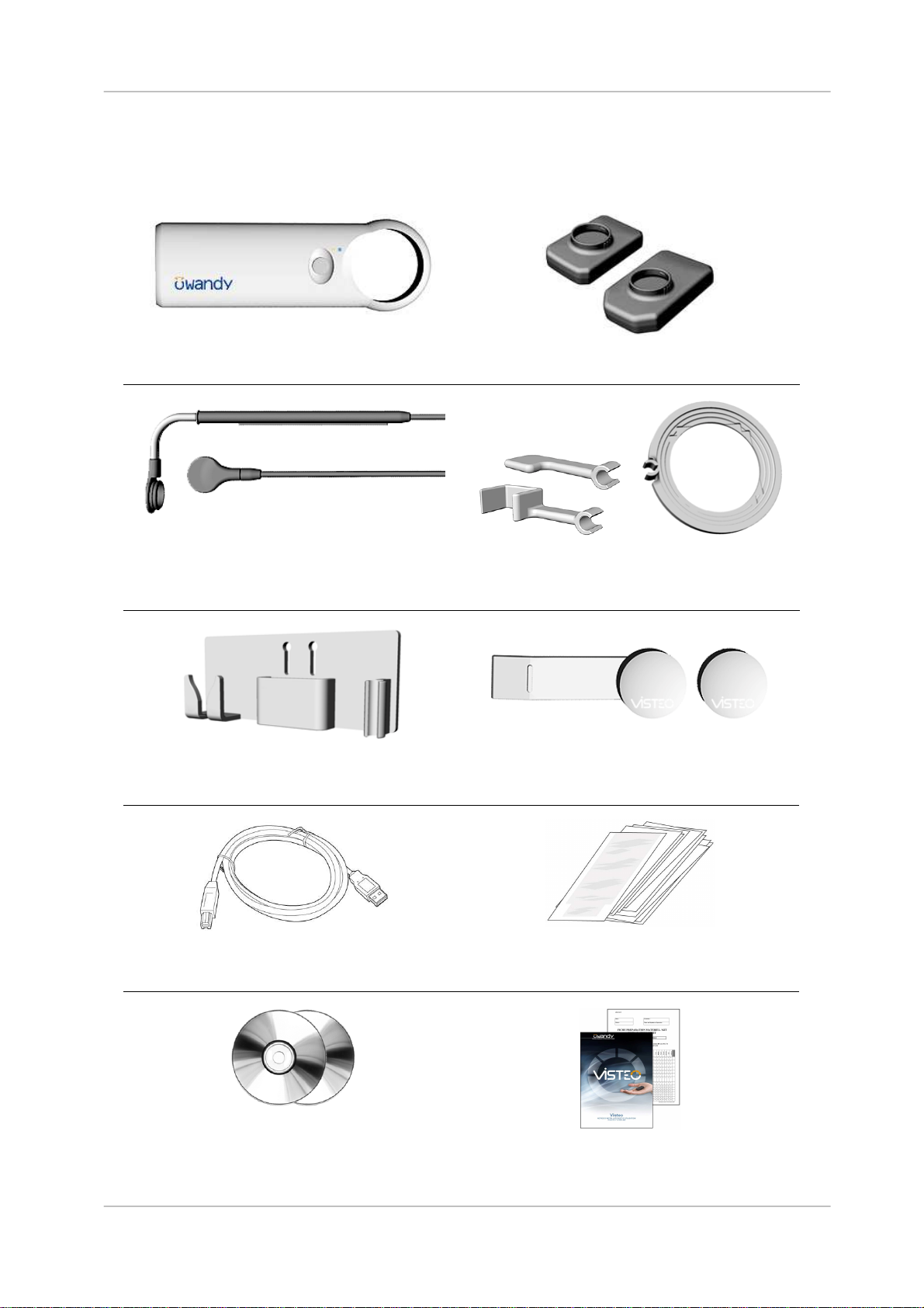
2
CONTENTS ................................................................................................................................. 6
3
INSTALLATION........................................................................................................................... 7
3.1
P
RECAUTIONS
............................................................................................................................ 7
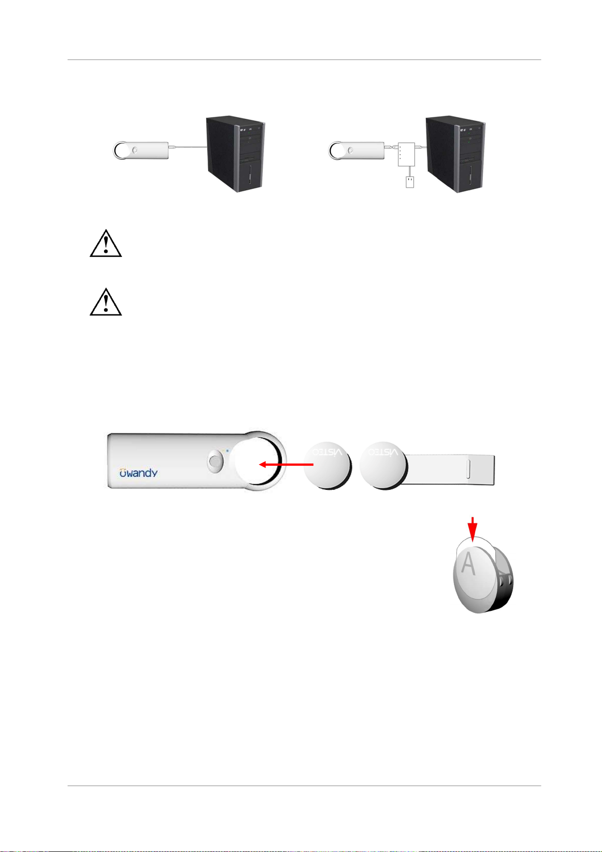
3.2
E
QUIPMENT INSTALLATION
.......................................................................................................... 8
3.3
S
OFTWARE INSTALLATION
......................................................................................................... 11
3.4
C
ONFIGURATION IN THE
O
WANDY IMAGING SOFTWARE
............................................................... 13
3.5
S
HARING THE SENSOR AND BOX BETWEEN DIFFERENT WORKSTATIONS
........................................ 15
4
USE............................................................................................................................................ 16
4.1
P
RECAUTIONS
.......................................................................................................................... 16
4.2
L
IGHTS AND BUTTON ON THE BOX
.............................................................................................. 16
4.3
P
OSITIONING ACCESSORIES
...................................................................................................... 17
4.4
U
SE OF THE
O
WANDY
XIO
S
TAND
A
LONE SOFTWARE
................................................................. 20
4.5
A
CQUISITION OF AN IMAGE
........................................................................................................ 22
4.6
E
XPOSURE TIME
....................................................................................................................... 24
5
HYGIENE AND MAINTENANCE .............................................................................................. 25
5.1
H
YGIENE AND DISINFECTION
...................................................................................................... 25
5.2
R
ECOMMENDED CLEANING AND DECONTAMINATION PROCEDURE
................................................ 26
5.3
M
AINTENANCE
.......................................................................................................................... 26
6
TROUBLESHOOTING............................................................................................................... 27
6.1
G
ENERAL
................................................................................................................................. 27
6.2
I
MAGE QUALITY
......................................................................................................................... 28
7
SPECIFICATIONS..................................................................................................................... 29
8
OPTIONAL KITS AND ACCESSORIES................................................................................... 30
8.1
O
PTIONAL KITS
......................................................................................................................... 30
8.2
A
CCESSORIES
.......................................................................................................................... 30
The manufacturer, Owandy, reserves the right to make modifications to its products or to their specifications in order to
improve the performance, quality, or ease of production. Specifications of products or accessories may be modified
without prior notice.
No part of this manual may be reproduced without the prior consent of the manufacturer, Owandy.
Language of original document: French.
0459
6 Allée Kepler
F-77420 Champs sur Marne
France
Telephone : +33 1.64.11.18.18
Fax : +33 1.64.11.18.10