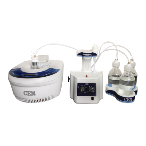
CEM Razor User manual

Razor®
Rapid Peptide Cleavage System
Manual

THIS PAGE INTENTIONALLY LEFT BLANK

Contents
Safety
Safety Notations 1
Introduction
About the Instrument 2
Recommended Cleavage Parameters 2
Important Safeguards
Instrument Safeguards 3
Instrument Overview
Razor Hardware 4
Accessory Kit 5
System Installation
System Setup 6
Assign the Set Temperature 8
Peptide Cleavage
Prepare the Razor 9
Rinse Resin Prior to Cleavage 10
Cleavage 12
Precipitation and Analysis 12
Sample Position Cleaning 13
Maintenance
Cavity Ceiling Cleaning 14
Sample Position Clog 14
System Specifications
Location 15
Electrical Requirements 15
Environmental Constraints 15
Warranty
Limited Warranty Information 16
Technical Assistance
Applications Support 18
Technical Support 18
Contact Information
CEM Corporation Headquarters 19
CEM International Subsidiaries 19
CEM Distributors 20

THIS PAGE INTENTIONALLY LEFT BLANK

1Safety
Safety
Safety Notations
This manual uses three safety alert words at points in the documentation where the user should be aware of
potential hazards. The safety alerts are shown in color-coded boxes. The three words – NOTE, CAUTION, and
WARNING – indicate differing levels of observation or action as described below:
NOTE
A NOTE is intended to provide emphasis on procedures that may be misinterpreted or overlooked, or to
clarify confusing situations.
CAUTION
A CAUTION is intended to provide essential information and to emphasize procedures that, if not strictly
followed, may result in improper instrument operation.
WARNING
A WARNING is intended to emphasize dangerous or hazardous conditions that may result in personal
injury to the user and/or damage or destruction of the instrument.

2 Introduction
Introduction
About the Instrument
The Razor parallel cleavage system is an isolated heating module designed for performing the peptide cleavage
step. The isolated module provides the advantage of protecting the Liberty Blue™system from the harsh reagents
required for the cleavage all while allowing the use of heat to provide high quality peptides in excellent yields in a
fraction of the time.
This manual is intended for use by both novice and experienced users for the operation and maintenance of the
Razor.
Recommended Cleavage Parameters
In Fmoc synthesis, the removal of the peptide from the solid support is typically accomplished with triuoroacetic
acid (TFA). Because the side chain protecting groups used in Fmoc synthesis are acid labile, a single step both
cleaves the peptide from the resin and removes the protecting groups. Various scavenger molecules are added
to the TFA to prevent the cleaved protecting groups from reattaching to the peptide. The particular scavengers
used depend on the specic peptide sequence. Common scavengers include water (scavenges t-butyl cations),
triisopropyl silane (TIS, scavenges trityl and Pbf cations), ethane dithiol (EDT, scavenges t-butyl cations, reduces
oxidation of Cys/Met side chains), dioxa-1,8-octane-dithiol (DODT, scavenges t-butyl cations, suppresses oxidation
of Cys/Met side chains), phenol (protects Tyr and Trp side chains from oxidation), and thioanisole (aids in removal
of Pbf protecting groups from Arg(Pbf), suppresses oxidation of Cys/Met side chains).
CEM recommends using a cocktail of TFA/TIS/H2O/DODT (92.5/2.5/2.5/2.5).

3Important Safeguards
Important Safeguards
General guidelines for safe operation of the Razor system are presented below and all specic safety messages
are located throughout the manual.
Instrument Safeguards
• Service can only be performed by an authorized CEM service technician. The system must be disconnected from
power supply prior to servicing.
• Do not tamper with the Razor, including actions such as removing any components of the housing.
• The Razor must be installed in a ventilated fume hood pulling at least 30.5 CFM.
• Adequate ventilation should be provided for preparation of reagents and solvents for use on the system.
• If any damage to the instrument is noted, do not attempt instrument operation.
• Cleavage vessels must be purchased directly from CEM Corporation or through its authorized dealer network.
• If it is necessary to use an extension cord, use only a 3-wire extension cord that has a 3-blade grounding plug
and a 3-slot receptacle that will accept the plug from the instrument. The marked rating of the extension cord
must be equal to or greater than the electrical rating of the instrument.
• If instrument is used in a manner not specied by CEM Corporation in this manual, then the protection provided
by the equipment may be impaired.
• Proper precautions must be taken to avoid contact with reagents or reagent vapors. Protective gear should be
worn as outlined in the user’s safety program for hazardous materials and the reagent manufacturer’s safety
data sheet. Refer to these guidelines for proper handling and disposal of the reagents. Dispose of all waste in
accordance with all applicable local, state, and federal health and safety recommendations.
• Do not position the Razor so it is difcult to access the power, heat or vacuum switches

4 Instrument Overview
Instrument Overview
For a list of parts and part numbers, visit our website at www.cem.com. A list of parts can be found on the
“Products” page under “Razor.”
Razor Hardware
1
11
9
8
7
6
5
4
3
2
10
12
Item Item
1 Vessel Hot Block 7 Light Switch
2 Valve Panel: Sample Positions, Vent, and Drain knobs 8 Power Switch
3Vessel Tray 9 Heat Switch
4 Temperature Control Panel 10 Vacuum Switch
5 Cavity 11 Vacuum Gauge
6 Locking Lever 12 Ports: Vent, Vacuum, and Waste

5Instrument Overview
Accessory Kit
Vessel Rack Vessel Rack Cover Waste Tubing Bundle
P/N 547205 P/N 170875 P/N 547225
GL45 Waste Cap Razor Power Supply Position Cleaning Tool
P/N 167545 P/N 267080 P/N 547300
1 L Glass Bottle (no cap) Vessel Caps 50 mL Centrifuge Tubes
P/N 167550 P/N 170810 P/N 330090 (Set of 25)
Cleavage Vessel Spill Tray
P/N 170897 (Pack of 60) P/N 170530
P/N 170900 (Pack of 120)
*Power Cord not pictured as it is region specic.

6 System Installation
System Installation
System Setup
1. Remove the Razor from it’s shipping box and place the system in a well ventilated fume hood.
WARNING
The Razor must be installed in a ventilated fume hood pulling at least 30.5 CFM.
2. Connect the power cord to the power supply box. Attach the power supply to the connector on the rear of the
system, and plug the power cord into an appropriate outlet.
3. Connect the waste tubing.
3.1. Connect the tubing bundle to the appropriate ports on the side of the system: vacuum and waste.
3.2. Attach the opposite end of the tubing bundle to the GL45 cap. Both ports on the cap are the same so
tube placement is indifferent.

7System Installation
3.3. Secure the cap to the 1 L bottle.
4. Insert the spill tray.
5. Load the vessel tray with 12 clean 50 mL centrifuge tubes, and slide into the Razor cavity. Make sure the tray
has been pushed all the way to the back of the cavity.
6. Lock the vessel tray in place by pulling the locking lever down.

8 System Installation
7. Position the system power and lights to ON using the power switches on the rear of the system.
8. Position the system heat to ON using the power switch on the left side of the system.
Assign the Set Temperature
1. Using the up and down arrows on the temperature screen, set the temperature between 40 ºC and 42 ºC. The
set temperature is displayed in green in the lower right corner of the screen.
2. The system is ready for use when the current temperature matches the set temperature. The current tempera-
ture is displayed in white in the center of the screen.

9Peptide Cleavage
Peptide Cleavage
WARNING
Proper precautions must be taken to avoid contact with reagents or reagent vapors. Protective gear should
be worn as outlined in the user’s safety program for hazardous materials and the reagent manufacturer’s
safety data sheet. Refer to these guidelines for proper handling and disposal of the reagents. Dispose of
all waste in accordance with all applicable local, state, and federal health and safety recommendations.
Prepare the Razor
1. Verify the current system temperature has reached the set temperature; 40-42 ºC. See “Assign the Set Tem-
perature” for details.
2. Load the vessel tray with twelve clean 50 mL centrifuge tubes and slide into the Razor cavity. Make sure the
tray has been pushed all the way to the back of the cavity.
CAUTION
The vessel tray must have all 12 centrifuge tubes loaded to operate correctly. If a tube is missing, the
system will fail to create a vacuum during draining.
3. Lock the vessel tray in place by pulling the locking lever down.
4. Switch the vacuum pump ON using the power switch on the right side of the system. Verify there are no leaks

10 Peptide Cleavage
by checking the vacuum gauge below the vacuum switch, and then turn the pump OFF.
• If the gauge does not read between 5 and 15 psi, verify the following
• Re-seat the vessel tray
• Verify all knobs are set to CLOSE
• See the “Cavity Ceiling Cleaning”section.
Rinse Resin Prior to Cleavage
NOTE
CEM recommends using the wash position to rinse the resins. The wash solvent will drain directly to the
waste bottle. The wash position can then be rinsed and will be ready for the next sample. Alternately, the
resin can be rinsed in the sample position but the 50 mL centrifuge tubes will need to be replaced with
clean, dry tubes before cleavage analysis.
1. Insert a new, clean cleavage vessel into the wash position on the Razor hot block.
2. Transfer the resin with the completed peptide into the cleavage vessel.
3. Turn the vacuum pump ON and turn the drain knob to OPEN to drain any solvent from the resin.

11Peptide Cleavage
CLOSE OPEN
4. Rinse the resin three times with an appropriate volume of dichloromethane (DCM).
4.1. With the vacuum pump still ON, turn the drain knob to CLOSE.
4.2. Add appropriate volume of dichloromethane (DCM) to rinse the resin.
4.3. Turn the drain knob to OPEN to drain the liquid.
4.4. Repeat steps 4.1 - 4.3 (2) two additional times.
CAUTION
DCM should be used to rinse the resin prior to cleavage to ensure that no residual DMF is present before
adding the cleavage cocktail.
5. After rinsing, CLOSE the drain knob.
6. Move the cleavage vessel containing the resin to one of the sample positions on the Razor hot block.
7. Clean the wash position.
7.1. Insert a clean resin tube into the wash position
7.2. With the vacuum pump still ON and the drain knob set to CLOSE, add ~30 mL of dichloromethane
(DCM) or methanol.
7.3. Turn the drain knob to OPEN to drain the liquid.
7.4. Once all liquid has drained, CLOSE the drain knob.
8. Up to 11 additional reaction tubes can be added to the Razor hot block. Prepare the additional cleavage ves-
sels as outlined above. Sample positions knobs should be set to CLOSE to prevent premature draining.
NOTE
An optional Teon®cap can be placed on reaction vessels during cleavage to reduce evaporation.

12 Peptide Cleavage
9. Turn the vacuum OFF.
Cleavage
1. Verify that the appropriate sample position knob and vent knob are set to CLOSE and add the cleavage cocktail
to the cleavage vessel. The cleavage cocktail should be double that of the volume of the resin bed. For 0.25
mmol cleavages, the resin mixture may be visible above the hot block. See “Recommended Cleavage Parame-
ters” for details.
2. Allow the vessel(s) to remain in the Razor for 30 minutes each at 40 ºC.
NOTE
If the peptide has multiple Arg residues, increase the cleavage time by 5 min for every additional Arg after
the third Arg residue. Do not exceed 45 min for the total cleavage time.
3. After the appropriate amount of time has passed for cleavage, turn the vacuum pump ON.
4. Turn the appropriate sample position knob to OPEN to begin draining the cleavage solution.
CAUTION
Drain one cleavage position at a time, do not drain multiple positions at once.
5. Once liquid has been removed, CLOSE the sample position knob.
6. Turn the vacuum pump OFF.
7. Move the vent knob to the OPEN position to release pressure.
8. Unlock the vessel tray by pulling the locking lever down.
9. Turn the vent knob to CLOSE.
10. Carefully remove the vessel tray from the Razor cavity. The centrifuge tube(s) containing the cleaved peptide
are now ready for precipitation and analysis..
• If moving the tray to a new location, the vessel tray cover can be installed.
11. Discard the cleavage vessel(s) and resin.
12. Clean the used sample position after every run to prevent valve clogging and contamination. See “Sample
Position Cleaning” for details.
13. Empty the waste bottle.
13.1. Remove the waste cap from the bottle and discard the waste.
13.2. Firmly re-secure the cap.
Precipitation and Analysis
1. To precipitate the cleaved peptide:
1.1. Add up to 50mL (or 8 times the amount of drained liquid) ice cold ether. If the volume exceeds 50 mL,
use a second centrifuge tube.
NOTE
The ether should be ice cold to ensure maximum precipitation of the peptide.
1.2. Centrifuge the peptide solution for 5 min at 3500 rpm or until a white or clear peptide pellet forms on

13Peptide Cleavage
the bottom of the tube. Repeat the centrifuge process if necessary to remove any oating particles.
1.3. Decant the ether, leaving the precipitated peptide in the tube.
1.4. The peptide can be resuspended in ice cold ether and centrifuged again to ensure any remaining pro-
tecting group byproducts have been washed away.
2. The peptide can be analyzed immediately on an HPLC or UPLC for crude purity analysis. Alternatively, the pep-
tide can be lyophilized over night prior to analysis.
2.1. To lyophilize, suspend the peptide gel in 10% acetic acid in deionized water then freeze with liquid
nitrogen before placing on the lyophilizer.
Sample Position Cleaning
To prevent valve clogging and contamination, used Sample Position(s) must be cleaned after every run.
1. Load the vessel tray with twelve (12) 50 mL centrifuge tubes, and slide into the Razor cavity. Make sure the
tray has been pushed all the way to the back of the cavity.
CAUTION
The vessel tray must have all 12 centrifuge tubes loaded to operate correctly. If a tube is missing, the
system will fail to create a vacuum during draining.
2. Lock the vessel tray in place by pulling the locking lever down.
3. Insert an empty cleavage vessel into the appropriate cleavage position.
CAUTION
Do not add liquid directly to the sample position without a cleavage vessel in position.
4. Turn the vacuum pump ON and turn the drain knob to CLOSE.
5. Add ~30 mL dichloromethane (DCM) or methanol.
6. Turn the drain knob OPEN to drain the liquid.
7. After rinsing, CLOSE the drain knob and turn the vacuum OFF.
8. Move the vent knob to the OPEN position to release pressure.
9. Unlock the vessel tray by pulling the locking lever down.
10. Turn the vent knob to CLOSE.
11. Remove the vessel tray and discard the wash solvent.
12. Replace the used 50 mL centrifuge vessels with clean vessels.
13. Load the vessel tray with twelve (12) 50 mL centrifuge tubes, and slide into the Razor cavity. Make sure the
tray has been pushed all the way to the back of the cavity.
14. To empty the waste bottle, remove the waste cap and discard the waste then rmly re-secure the cap.

14 Maintenance
Maintenance
Cavity Ceiling Cleaning
As needed: Wipe down the ceiling of Razor cavity to ensure centrifuge tubes will seal when vessel tray is locked
into position.
1. Remove the vessel tray from the cavity.
2. Dampen a clean soft cloth with methanol and wipe each seal.
3. Allow the methanol to dry before inserting the vessel tray and continuing use.
Sample Position Clog
If a sample position is clogged, use the cleaning tool to unclog the position.
1. With the vacuum OFF, unlock the vessel tray by pulling the locking lever down.
2. Remove the vessel tray from the Razor cavity.
3. Turn the sample position knob to OPEN.
4. Insert the cleaning tool into the top of the hot block to remove the obstruction.

15System Specications
System Specifications
Location
• A fume hood that pulls a minimum of 30.5 CFM at point of connection
• Provides adequate space for sample handling
• Has a dedicated, grounded outlet no more than 10.6 feet (3.2 M) from unit
• Is free from vibration of large equipment
• Designated area with a sturdy workbench capable of handling at least 27.2 lbs (12.3 kg)
• Instrument Dimensions: 15” (38.1 cm) W x 12” (30.5 cm) D x 13.5” (34.3 cm) H
• Recommended counter space: 16” (40.6 cm) W x 21” (53.3 cm) D x 25.5” (64.8 cm) H
• The above provides at least 9 inches (22.9 cm) of open space in front of the unit to add the vessel tray, 12
inches (30.5 cm) of working room above the unit, and room to access switches on the left and right sides of
the unit
• Do not position the Razor so it is difcult to access the power, heat or vacuum switches
Electrical Requirements
• 100 - 240 VAC, 50/60 Hz, 6.25 A
• Line voltage must not vary more than 10% of its specied level
• Dedicated, grounded outlet no more than 10.6 feet (3.2 M) from unit
• Instrument is supplied with a region specic power cord or an adequately rated power cord may be use
• External power supply with non-replaceable fuses
Environmental Constraints
• A fume hood that pulls a minimum of 30.5 CFM at point of connection
• Indoor use only
•Altitude up to 2000 m
•Operating Temperature range of 50°F (10°C) to 85°F (29.4°C)
•Relative humidity range of 10 % to 85%, non-condensing
•Overvoltage Category II
•Pollution degree 2

16 Warranty
Warranty
Limited Warranty Information
What Is Covered:
CEM Corporation warrants that the instrument will be free of any defect in parts or workmanship and will, at its
option, replace or repair any defective part (excluding consumables) or instrument.
For How Long:
This warranty remains in effect for 365 days from date of delivery to the original purchaser.
What Is Not Covered:
This warranty does not cover parts or workmanship damaged due to:
• Neglect, abuse or misuse,
• Damage caused by or to test samples,
• Damage incurred during instrument relocation,
• Damage caused by or to any attached equipment,
• Use of incorrect line voltages or fuses,
• Fire, ood, “acts of God” or other contingencies beyond the control of CEM Corporation,
• Improper or unauthorized repair, or
• Any other damage caused by purchaser or its agents.
Responsibilities of Purchaser:
To ensure warranty coverage, the purchaser must:
• Use the instrument according to directions,
• Connect the instrument properly to a power supply of proper voltage,
• Replace blown fuses,
• Replace consumables and
• Clean the instrument as required.
How to Get Service:
Purchaser should contact the Service Department of CEM Corporation or the nearest CEM subsidiary or distributor
for return authorization and for proper crating and shipping instructions to return instrument, freight prepaid, for
service. On-site repairs by an authorized service technician are available through the CEM Service Department.
Travel costs will be charged to the purchaser for on-site repairs.
Within the U.S. Outside the U.S.
CEM Corporation CEM Corporation
3100 Smith Farm Rd. 3100 Smith Farm Rd.
Matthews, NC 28105-5044 Matthews, NC 28105-5044
(800) 726-5551 (704) 821-7015
Fax: (704) 821-4368 Fax: (704) 821-4368
Other manuals for Razor
1
Table of contents
Other CEM Laboratory Equipment manuals