Oxford Plasmalab 80 Plus User manual

NANOSYSTEMFABRICATIONFACILITY(NFF),HKUST
Version1.0Pa
g
e 1 of 24
Standard Operating Manual
___________________________________________________________
Oxford Plasmalab 80 Plus Plasma Etcher

NANOSYSTEMFABRICATIONFACILITY(NFF),HKUST
Version1.0Pa
g
e 2 of 24
Contents
1. Picture and Location
2. Process Capabilities
2.1 Cleanliness Standard
2.2 Available Etching Materials
2.3 Performance of the Oxford Plasmalab 80 Plus Plasma Etcher
3. Contact List and How to Become a Qualified User
3.1 Emergency Responses and Communications
3.2 Training to Become a Qualified User
4. Operating Procedures
4.1 System Description
4.2 Safety Warnings
4.3 Initial System Checks
4.4 Status Checks
4.5 Venting the Chamber (Before Loading Wafers)
4.6 Opening the Process Chamber
4.7 Inspecting the Chamber Before Use
4.8 Load Wafers
4.9 Closing the Process Chamber
4.10 Pumping Down the System for Dry etching
4.11 Start your Dry Etching Process
4.12 Venting the Chamber (Before Unloading Wafers)
4.13 Pumping the System Down for Idle
5. Appendix

NANOSYSTEMFABRICATIONFACILITY(NFF),HKUST
Version1.0Pa
1. Picture and Location
Chamber
Computer
OxfordPlasmalab80
PlusPlasmaEtcher
Fig 1: This tool is located at NFF Enterprise Center Cleanroom Room 4162
2. Process Capabilities
2.1 Cleanliness Standard
Oxford Plasmalab 80 Plus Plasma Etcher is “Non-Standard” equipment for dry
etching process.
g
e 3 of 24

NANOSYSTEMFABRICATIONFACILITY(NFF),HKUST
Version1.0Pa
g
e 4 of 24
2.2 Available Etching Materials
The following sources are available in Oxford Plasmalab 80 Plus Plasma Etcher.
LTO, Thermo Oxide, Silicon Nitrite, Poly-silicon and Silicon on 4” wafer or small
piece sample.
NOTE: Consult NFF EC staff prior to do new materials other than above listed. Hazardous or
Radioactive materials are not allowed to be etched in Oxford Plasmalab 80 Plus Plasma Etcher.
2.3 Performance of the Oxford Plasmalab 80 Plus Plasma Etcher
What CAN do:
Oxford RIE 80+ can etch thin films thickness (≥400A thick) or thick films
thickness (≤100um thick).
What CANNOT do:
Oxford Plasmalab 80 Plus Plasma Etcher could not replace ICP DRIE for
etching thick films, e.g. over 100um
It could not be used for photoresist Stripping, due to photoresist is for mask
protection only.
Users cannot modify the recipes’ parameters, such as chamber pressure, RF
power, process gas flow and chiller temperature.
Process time cannot over 20 minutes per run and 5 -10 minutes s allowed for
chamber cooling.

NANOSYSTEMFABRICATIONFACILITY(NFF),HKUST
Version1.0Pa
g
e 5 of 24
3. Contact List and How to Become a User
3.1 Emergency Responses and Communications
Security Control Center: 2358-8999 (24hr) & 2358-6565 (24hr)
Safety Officer: Mr. Wing Leong CHUNG 2358-7211 & 64406238
Deputy Safety Officer: Mr. Man Wai LEE 2358-7900 & 9621-7708
NFF EC Technician: Mr. Peter Yiu Cheong PUN 2358-7225 & 2358-7218
NFF Phase 2 Technician: Mr. Wilson Pui Keung YIP 2358-7894
3.2 Training to Become a Qualified User
Please follow the procedure below to become a qualified user.
1. Read all materials on the NFF website concerning the Oxford RIE 80+.
2. Send an e-mail to NFF requesting Oxford RIE 80+ safety operation training.
Scheduling can take up to several weeks due to the many requests coming in
for this tool.
4. Operating Procedures
4.1 System Description
Oxford Plasmalab 80 Plus Plasma Etcher is a plasma processing system, which can be
configured to carry out reactive ion etching(RIE).
The chamber arrangement for a typical RIE process is shown as below:
The electrode is powered by a 13.56 MHz RF generator. The associated
auto-matching tuner unit is positioned close to the driven electrode.

NANOSYSTEMFABRICATIONFACILITY(NFF),HKUST
Version1.0Pa
Fig 2: Typical RIE configuration
Fig 3: Backing and turbo molecular, turbo process and turbo bypass pump down
Backing and turbo pumps: process through the turbo pump and pump down by
bypassing the turbo
With this arrangement, the chamber can be vented and roughed out without stopping
the turbo pump.
g
e 6 of 24

NANOSYSTEMFABRICATIONFACILITY(NFF),HKUST
Version1.0Pa
Description of Oxford RIE 80+
Fig 3: Description of major system components for Oxford RIE 80+.
A stainless steel cabinet with removable access panels encloses the mechanical and
electronic components of the system and provides a support for the processing
chamber. Turbo molecular and rough pumps are mounted separately from the main
console cabinet.
The chamber lid and integral top electrode are raised and rotated clear of the chamber
base and substrate table by a pneumatic hoist mechanism. This provides access to the
table for loading and removal of substrates. The hoist is, for safety consideration,
operated by pressing two buttons simultaneously.
The cylindrical aluminum chamber has a view port in its upper section and three ports,
for roughing, extraction and pressure gauges, in its base. Gas is supplied to the upper
electrode “shower head” via channels in the two halves of the chamber. Moreover,
g
e 7 of 24

NANOSYSTEMFABRICATIONFACILITY(NFF),HKUST
Version1.0Pa
coolant cooling is provided for the table where Reactive Ion Etching process is used.
Controls and indicators
The controls and indicators are mounted on the front of the unit as shown as below:
Fig 4: diagram of controls and indicators
g
e 8 of 24

NANOSYSTEMFABRICATIONFACILITY(NFF),HKUST
Version1.0Pa
Emer
g
enc
y
OFF Button
Power ON LED
(
L.H.S.
)
S
y
stem ON LED
(
R.H.S.
)
Viewing port
Chamber Hoist Up/Down
Selection Switch
Chamber Hoist Buttons
Fig 5: Real picture of of controls and indicators
Chamber Hoist buttons and up/down selection switch: To raise or lower the chamber
top, the up/down selection switch is set to the required position, then both chamber
hoist buttons are pressed.
Emergency Off (EMO) button: When pressed, the system is shut down.
Power On indicator: Indicates the electrical power is connected to the machine.
System On button: Switches the system power on.
System On indicator: Indicates that the system is powered up.
System Off button: Switches the system power off.
g
e 9 of 24

NANOSYSTEMFABRICATIONFACILITY(NFF),HKUST
Version1.0Pa
g
e 10 of 24
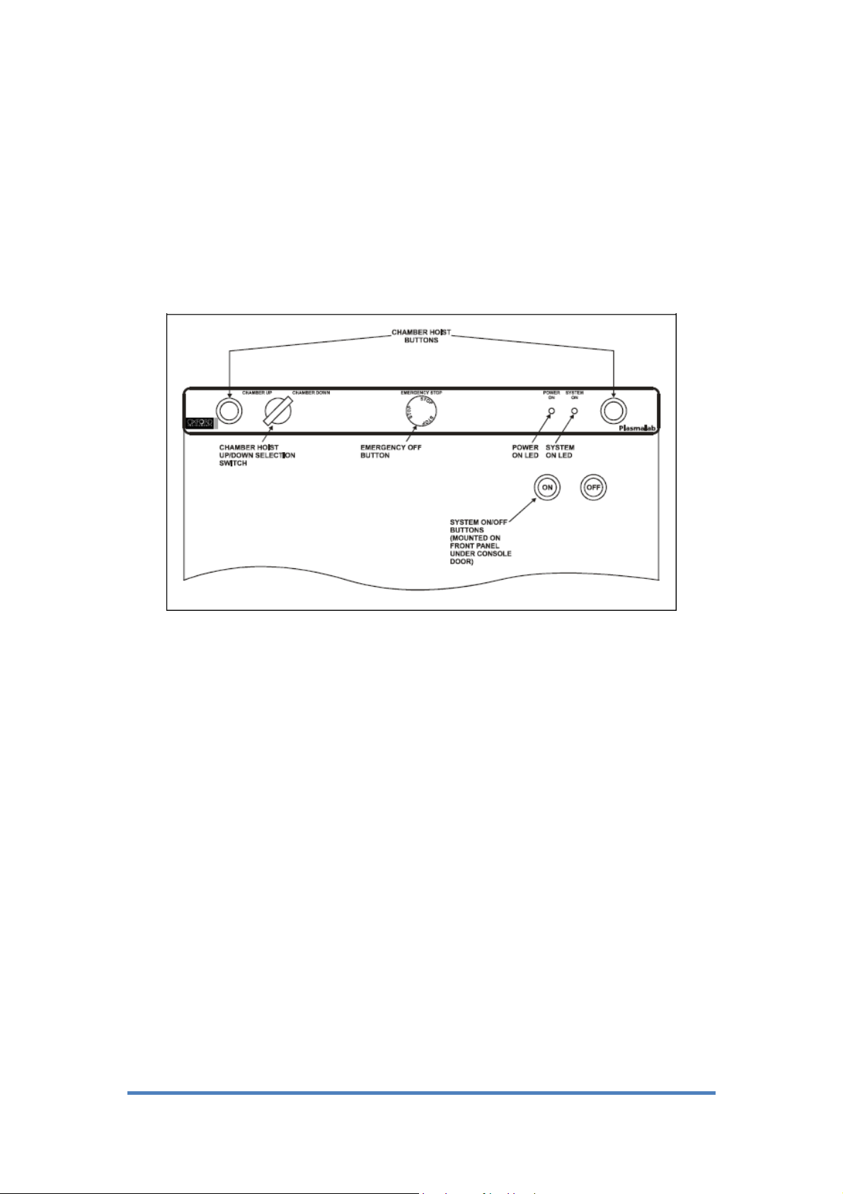
Emergency off and Interlock facilities
Emergency off (EMO) and interlock facilities are provided to shut down the machine
in an emergency and to stop process until the system is fully initiated. An emergency
off switch, with normally-closed contacts, is mounted on top of the console. The
switch is activated by pressing a red “Emergency Off” button.
PLC interlock chain
The interlock chain is monitored by the software, but acts independently. It is also
supplemented by machine protection sensors, which operate only via the software.
To enable RF power:
1. The 600 mbar vacuum switch (‘Vacstat’) must be at low pressure
2. The process chamber lid must be closed (or its hoist down)
3. The primary process pump must be running
4. The primary process pressure gauge (normally a capacitance manometer) must be
on scale
5. The load lock inter-chamber valve (where fitted) must be closed
6. Customer-supplied external alarm devices must be at safe state
7. The inert gas purge to the primary process pump must be flowing.
To enable process gases:
1. RF power must be enabled.
2. The gas box lid must be closed.
3. Specific gases can be set in the gas box hardware to be mutually exclusive, so
they cannot be turned on together.

NANOSYSTEMFABRICATIONFACILITY(NFF),HKUST
Version1.0Pa
g
e 11 of 24
Machine protections fitted where appropriate:
1. A nitrogen pressure switch, to detect adequate purge pressure to turbo molecular
pump bearings or;
2. A nitrogen flow meter, to detect purge gas flow to pump bearings.
3. Water flow switch.
4.2 Safety Warnings
This equipment can cause injury if not used in a cautious manner.
1. Do not operate the system if any of the doors, panels or covers is removed.
2. Ensure that all personnel who operate this equipment are trained to use the
equipment, and are alerted to the range of hazards present.
3. When opening the processing chamber, ensure that personnel stand clear of
the chamber lid and hoist assembly.
4. Close chamber door carefully, ensure that personnel vacate the vicinity of the
door and its operating mechanism before it is closed to avoid trapped fingers
etc.
5. Ensure that you do not leave tweezers between the lid and the base, damage
the equipment could occur.
6. When the compressed air is first applied to the system, the initial chamber lid
movement will be repaid unless the “HOIST” buttons are operated
intermittently.
7. If the sample to be etched contains photo resist, then the substrate must be
baked immediately before placing it in the chamber.

NANOSYSTEMFABRICATIONFACILITY(NFF),HKUST
Version1.0Pa
g
e 12 of 24
8. Never smoke or eat in the “clean room” or where gases are stored. In addition
to the fire risks and particulate contamination presented by smoking, some
chemicals when burnt generate carcinogenic or toxic compounds.
Operation Rules
1. If an equipment failure while being used, never try to fix the problem by
yourself. Please contact NFF staff.
2. Do not operate equipment unless you are properly trained and approved by
NFF staff.
3. Do not leave an on-going experiment unattended.
4.3 Initial system checks
1. Make sure the System Interlocks (-15Volts, +15Volts, +24Volts, Gas-Pod
Interlock and Water Flow Generator) are all at green light (ON Mode).
2. Make sure the Pump-down System (rough pump, APC valve, Gate valve,
Turbo molecular pump (at speed) and Turbo backing valve) are all at green
light (ON mode).
3. Make sure the Process Interlock are all shown ready, e.g. Lid->Close, Process
Interlock->OK, Penning 1.88e-06Torr->Base pressure reached (1.80e-05Torr),
Cm gauge->0 mTorr and Vent Time left->0 secs.

NANOSYSTEMFABRICATIONFACILITY(NFF),HKUST
Version1.0Pa
g
e 13 of 24
Fig 6: System, Process and Pump-down Interlocks
Pump-down Interlocks
Pressure Interlocks
System Interlocks
4.4 Status checks
1. Check the NFF website for reservations, problems and to see if it is already
enabled by another user.
2. Check for an EMPTY sign attached to the machine. Do not use if an IN USE
signs or MAINTENANCE sign is there. Check for problem notes.
3. The system is available if the initial system and status checks are normal.
Check-in the equipment and enable the system on NFF Machine Reservation
System. Place sign “IN USE” on the machine.
4.5 Venting the Chamber (Before Loading Wafers)
1. Ensure the Pump Control page is displayed (if necessary, select the System
Menu, then the Pumping option).
2. Select the STOP button, then the VENT button for the process chamber. Note

NANOSYSTEMFABRICATIONFACILITY(NFF),HKUST
Version1.0Pa
g
e 14 of 24
that the vent sequence is controlled by a timer to allow time for the turbo
pumps to be purged.
3. When the ´Vent Time Left´ timer has decremented to zero, the process
chamber has been vented. A clear gap between the chamber lid and the
chamber should be seen.
4.6 Opening the Process Chamber
To open the process chamber when it has fully vented, see the following procedure:
1. At the control panel, set the up/down selection switch to its chamber up
position.
2. Press both hoist buttons simultaneously. The chamber lid will raise and rotate.
3. When the chamber lid fully raised and stop rotate, release both hoist buttons.
4. If the lid does not open within 5 seconds, release the hoist buttons and try
again. If the lid does not open after the second attempt, please contact NFF EC
staff.
4.7 Inspecting the chamber before Dry Etching
1. Review the previous run in logbook to ensure there are no reported problems.
2. Fill in the log sheet with your name, NFF project number, reservation timeslot,
chamber pressure, RF power, gases flow rate and processing time being used.
3. Keep out of moisture of the chamber by minimizing the time of it at ambient
room temperature and pressure.

NANOSYSTEMFABRICATIONFACILITY(NFF),HKUST
Version1.0Pa
g
e 15 of 24
4.8 Load wafers
1. Place your sample face up in the center of the substrate holder. Before start up,
please wear gloves to reduce contamination and protect the hands.
2. Maximum 3 pieces of 4” full wafers are allowed into the chamber per run.
3. Check the O-rings in the chamber lid and substrate holder to ensure that they
are free of particles, dirt and no damage.
4.9 Closing the Process Chamber
To close the process chamber, follow the procedure as below:
1. At the control panel, set the up/down selection switch to its Chamber Down
position.
2. Press both hoist buttons simultaneously. The chamber lid will lower and
rotate.
3. When the chamber lid fully lowered and stop rotate, release both hoist buttons.
4. If the lid does not open within 5 seconds, release the hoist buttons and try
again. If the second attempt fails, please contact NFF EC staff.
4.10 Pumping Down the System for Dry Etching
To pump the system down, follow this procedure:
1. Ensure the Pump Control page is displayed (if necessary, select the System
Menu, then the Pumping option)
2. Ensure the status indicators (PSU Monitor, Water and Gas Pod Interlock) are
in green.

NANOSYSTEMFABRICATIONFACILITY(NFF),HKUST
Version1.0Pa
g
e 16 of 24
3. Ensure the process chamber lid is in its “down” position. If you intend to carry
out process run, you will need to open the process chamber lid, place a wafer
on the wafer holder in the process chamber, then close the process chamber
lid.
4. Select the Set Base Pressure button, and then enter the required process
chamber base pressure if different from the default (1.80e-05Torr). Click OK.
5. Click on the rough pump mimic to start the pump.
6. Select the Evacuate button for the process chamber. You will be prompted to
enter a wafer identity, either enter the identity and click OK, or click Cancel
(to pump down without the wafer identity in the chamber). The relevant valves
will operate and the process chamber will pumped downbe automatically.
4.11 Start your Dry Etching Process
Automatic Process Run:
1. Pump the system down.
2. Check that the system has pumped down to the base pressure. (The process
chamber message panel should display "Base Pressure reached").
3. Select the Process Menu, then the Recipe option. The recipe page is displayed.
4. Select the Load button and then select the required recipe from the displayed
list. Click OK.
5. If the material you want to etch and/or the recipe is not in the system, please
contact NFF EC staff and he will work with you to find an appropriate recipe
from the system.

NANOSYSTEMFABRICATIONFACILITY(NFF),HKUST
Version1.0Pa
g
e 17 of 24
6. To run the loaded recipe, select the Run button. The recipe will be
automatically run and the Chamber 1 page will be displayed to allow you to
monitor its progress.
7. If there is anything wrong, press the ABORT button to abort the process. Then
go to Step 4 and select the correct process.
8. Always verify by watching the view port to make sure the plasma is on and
the brightness and colour is correct. (IMPORTANT: Do not stare through the
viewing port at the plasma prolonged, viewing may damage your eyes)
Remarks:
You can pause the process at any time by selecting the PAUSE button. This will
cause the Step Time and the plasma power to stop with the current step time
indicated.
Re-starting the process will cause the process to continue from the time it was
paused. If, during the pause period, you change any of the process parameters, e.g.
gas demand, pressure etc.
You must press the START button for the changes made to come into effect, this
will cause the step timer to continue from the time it was paused.
You can stop the process at any time by selecting the STOP button. The system
will display the popup message "Process Complete", if required, you can then run
the same or another process.
When the "Process Complete" popup message displays, the system can be vented

NANOSYSTEMFABRICATIONFACILITY(NFF),HKUST
Version1.0Pa
g
e 18 of 24
or another process run can be carried out.
Creating and Editing Recipes
This page is used to assemble and store in memory for all set points and
instructions, which make up a Recipe for an Automatic Mode run. These
recipes consist of a sequence of process Steps.
The Recipe option (accessed from the PROCESS menu) displays the recipe
page for the process chamber. This page allows you to create / edit recipes and
the recipe steps that they contain.
Note: Before creating / editing recipes, make sure that you understand the
operation of key components of the system to ensure that recipes proceed as
expected.
Working with Recipes
Recipes are "built" using existing recipe steps, and edited as required. Within a
recipe, steps can be manipulated using the Step Commands pop-up menu
(accessed by clicking on the Recipe Steps field).
■Edit Step: Enables the selected (highlighted) step to be edited.
■Repeat Step: Repeats all subsequent steps until a Loop Step is reached. This
group of steps can be repeated any number of times. (When you select this
option, you are prompted to enter the number of times the group of steps is to
be repeated.)

NANOSYSTEMFABRICATIONFACILITY(NFF),HKUST
Version1.0Pa
g
e 19 of 24
■Loop Step: Terminates a Repeat Step group
■Insert Step: Creates "a gap"; above the selected step to allow another step to be
dragged into the list.
■Delete Step: Deletes the selected step from the list.
■Cancel: Closes the Step Commands pop-up menu.
4.12 Venting the Chamber (Before Unloading Wafers)
1. Ensure that the Pump Control page is displayed (if necessary, select the
System Menu, then the Pumping option).
2. Select the STOP button, then the VENT button for the process chamber. Note
that the vent sequence is controlled by a timer to allow time for the turbo
pumps to be purged.
3. When the ´Vent Time Left´ timer has decremented to zero, the process
chamber has been vented. A clear gap between the chamber lid and the
chamber will be present.
4.13 Pumping the System Down for Idle
To pump the system down, follow the procedure as below:
1. When finish samples unloading, close the process chamber lid and ensure that
the process chamber lid is in its “down” position.
2. Ensure that the Pump Control page is displayed (if necessary, select the
System Menu, then the Pumping option)
3. Ensure that the status indicators (PSU Monitor, Water and Gas Pod Interlock)

NANOSYSTEMFABRICATIONFACILITY(NFF),HKUST
Version1.0Pa
g
e 20 of 24
are in green.
4. Select the Set Base Pressure button, and then enter the required process
chamber base pressure if different from the default (1.80e-05Torr). Click OK.
5. Click on the rough pump mimic to start the pump.
6. Select the Evacuate button for the process chamber. You will be prompted to
enter a wafer identity, please click Cancel to pump down without the wafer
identity. The relevant valves will operate and the process chamber will be
automatically pumped down.
7. DON’T GO AWAY YET!
8. Monitor the chamber pressure to the base pressure at 1.80e-05Torr.
9. Clean up the area and return items to the proper locations.
10. Place an EMPTY sign on the machine.
11. Fill in the logbook completely and write down any problems.
Table of contents
Other Oxford Laboratory Equipment manuals
Popular Laboratory Equipment manuals by other brands

Tektronix
Tektronix Keithley 2380-500-30 Performance Verification Manual

BANDELIN
BANDELIN SONOCOOL 255 User instructions

WLD-TEC
WLD-TEC Sensorturn pro instruction manual

IET Labs
IET Labs W10MT3A Operation manual

Stuart
Stuart SC6/100V/50 Instructions for use

CMA Dishmachines
CMA Dishmachines VINCILAB 2 quick start guide