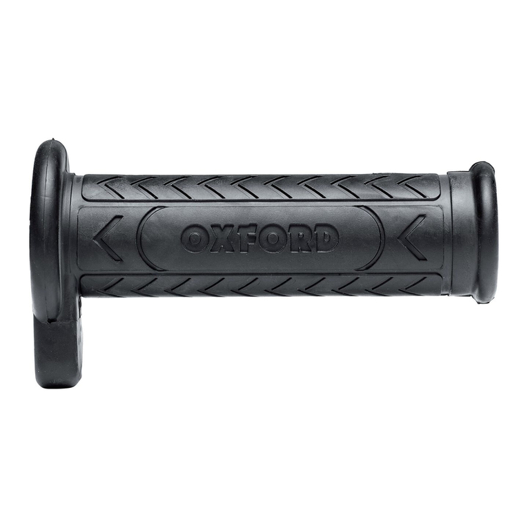
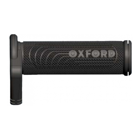
Oxford HotGrips OF690 Adventure User manual

OXFORD
™
v.8 switch 09/07/12
OF691 Touring
www.oxprod.com
Page 2-7
OF690 Adventure
OF696 Sports
Page 8-13 Page 14-19 Page 20-26 Page 27-32 Page 33-39

Oxford Hotgrips instructions v.8 switch - 09/07/12
2
Oxford HotGrips™: Fitting and User Instructions for part codes:
OF690 Adventure, OF691 Touring & OF696 Sports HotGrips™ with v.8 heat controllers.
A: Safety first: read carefully before fitting or using!
IMPORTANT: If you have any doubt about fitting your Oxford HotGrips™, immediately consult your local authorised
Oxford stockist for advice or alternatively visit our website www.oxprod.com and check for updates on the Frequently
Asked Questions.
WARNINGS:
i. Your HotGrips must only be connected and turned on when fitted to your handlebars as per the instructions.
ii. Before using the motorcycle/vehicle each time, please ensure that the fitted HotGrips are firmly glued to the
handlebar. Failure to do so could result in an accident or personal injury.
iii. Ensure that the throttle operates freely. Ensure that normal operation of the motorcycle is not affected. The Hotgrip
cables must not foul or restrict the operation of the brake or clutch levers.
iv. HOTGRIPS are designed for use with gloved hands. Do not allow bare skin to come into contact with your HotGrips
when turned “on”. Check the temperature for suitability before you set off. If the temperature becomes too hot
when on the move, pull over safely and turn the temperature down or turn the switch OFF if appropriate.
v. Do not leave the motorcycle unattended when the HotGrips are turned on. The heat regulation is only controlled by
the motorcyclist turning the heat controller up or down to suit the ambient weather conditions. If the grips are left
turned ON at a high heat setting whilst the motorbike is in a warm garage or in warm ambient conditions, damage
to the HotGrips or motorcycle could occur. Similarly if the Hotgrips are left turned on when fitted inside handlebar
muffs the temperatures may rise beyond a safe point and damage or even risk of fire could occur in the most
extreme situations. These are designed to be used in cold weather with the rider present.
vi. Replace the HotGrips when the pattern of the outer rubber wears away in any one area or the tread pattern
disappears.
vii. Regularly check the integrity of the attachment and materials of your HotGrips.
Do not use if in doubt and consult your local authorised OXFORD stockist.
viii. OXFORD Products will accept no liability for the consequences of grips, which have not been securely fitted. Liability
is limited to the replacement parts of the HotGrips in case of faulty materials or manufacture.
B: Parts list
Before fitting, check that the following parts are included in the kit:
• 1 x Left HotGrip (22mmØ I/D)
• 1 x Right HotGrip (25.6mmØ I/D)
• 1 x Intelligent Heat Controller (code: OFV8) and adhesive pad
• 1 x Universal bracket for switch - OF91 (tment may not be suitable for all vehicles)
• 1 x Wiring loom (1.52mtr long : code OF695L)
• Cable ties and grip superglue
Code/Grip Standard length (mm) Minimum length (mm)
OF690 Adventure 132 122
OF691 Touring 120 110
OF696 Sports 123 114

Oxford Hotgrips instructions v.8 switch - 09/07/12
3
Tools needed:
• A course and ne le for smoothing the throttle slider tube
• Glass paper for cleaning the handlebars
• Cable snippers or pliers
• Standard motorcycle tools to remove the seat, fairing panels and battery connections
C: Fitting and Wiring Instructions for Motorcycles
Your Oxford HotGrips are designed as a replacement for the handle bar grips already fitted to the motorcycle.
Hotgrips will t onto most motorcycles that use 22mm or 7/8” Ø handlebars. The grip has an open end to allow for
the bar end weight to be refitted without the need to trim the grip. If the end of the Hotgrip does need to be trimmed
to ensure that a bar-end weight can be tted without fouling the Hotgrips, then it is advisable to trim up-to the point
shown in the diagram below. This ensures that the heating elements do not get cut.
The left and right grip are different sizes:
One is designed to t over the left handlebar and has an internal diameter of approximately 22mm.
The other ts over the throttle slider on the right handlebar and has a diameter of approximately 25mm.
D: Fitting Procedure
1. Remove the existing handlebar grips.
2. Clean the left handlebar ensuring that the bars are smooth and free of glue and residue.
3. The bar should measure a consistent 22mm diameter.
4. When the right grip is removed there is a nylon throttle slider underneath. This may need to be removed and any
raised areas smoothed off to ensure that the diameter is a consistent 25.6mm.
This often involves filing off the raised ridges that were formed on the throttle slider.
Trim length here (picture below)
E: Trial fit the Oxford HotGrips
1. Always “dry t” the grip to the bar rst, to ensure that the grip is a snug t before using the adhesive.
2. The HotGrips have a unique internal tube that can expand to t over the handlebar.
3. This makes them easier to t over handlebars that have inconsistent diameter bars due to manufacturing
tolerances.
4. If the grips are too tight to slide on with only gentle effort, do not force them on or damage may occur. Check the
dimensions of the handlebars again and adjust as necessary.
5. If the HotGrips do not slide on easily, check if there is any excess rubber on the inside of the grip which may have
seeped through the expansion slot during manufacturing. If so, use a long file and gently remove the excess
rubber with the edge of the file.
6. When sliding the grips onto the handlebars it is possible to twist them into place until they reach the correct
finished position.
Trim lengths Trim lengths Trim lengths
OF690 Adventure OF691 Touring OF696 Sports

Oxford Hotgrips instructions v.8 switch - 09/07/12
4
F: Positioning on handlebars:
1. Position the grips so that the wires do not foul against the brake / clutch levers. The throttle grip should rotate freely
without obstruction and without stretching or pinching the wires. The ideal fitment position of the grips can vary
from bike to bike. We nd that an ideal position can be one whereby the wires of the grips sit just below the brake
and throttle levers. This position allows the Hotgrip wiring to be neatly attached to the clutch/brake cables and
usually prevents the wires from being strained. We have molded an arrow into the grip to indicate the position that
we consider to be the correct tted position on the handle bar. (picture below)
However some people prefer the wire of the grips to sit a safe clearance above the brake and clutch levers so that
the wire exits forward and relatively horizontal. When the throttle is opened the wire will then raise upwards and
away from the brake lever.
2. Before removing the grips for the nal tting procedure, it is important to connect the electrical wiring harness to
the battery and the grips. With the motorcycle engine running the grips can be switched on to make sure that the
grips operate as expected.
G: Final fitting of grips
1. Use the Super glue provided. It has been proven for this application and we cannot guarantee the suitability of an
alternative. Under no circumstances should the grip be tted to the handlebar without glue!
2. WARNING: The Superglue will bond skin and eyes in seconds. Keep out of reach of children.
• IT IS VERY IMPORTANT TO FIT THE GRIP IMMEDIATELY AND WITHOUT DELAY BECAUSE THE SUPERGLUE
PROVIDED WILL BOND THE HOTGRIPS TO THE BARS VERY QUICKLY. THIS IS PARTICULARLY RELEVANT WITH THE
THROTTLE SLEEVE AND HOTGRIPS
• Don’t let the glue drip onto paintwork. Shield paintwork appropriately.
3. Clutch side HotGrips:
• Apply plenty of glue along the length and around the diameter of the handle bar where the grip will nally sit.
• Push the grip into place ensuring that the HotGrips are positioned correctly so it does not foul the clutch
operation.
4. Throttle side HotGrips:
• If the grip is a very tight t over the throttle slider, then it is advisable to apply plenty of glue on the actual
plastic throttle slider on the inner most flange and less along the length of the throttle slider.This is to ensure
that the grip and glue do not set too early and half way up the throttle slider. We would also recommend to
apply a ring of glue around the outer end of the throttle slider as some of this will naturally be drawn up the
length of the throttle slider tube. If however the grip slides easily over the throttle slider then we would
recommend using plenty of glue around the whole circumference of the throttle slider to ensure a safe and
secure fitment.
Throttle open Throttle closed

Oxford Hotgrips instructions v.8 switch - 09/07/12
5
5. Be sure to act immediately to wipe away any excess glue with a dry cloth.
6. Allow the glue to dry for at least 24 hours before using. Ensure that the grips are rmly xed in place before use.
Do not use if the grip moves and seek advice immediately.
H: Wiring Harness Installation
1. Find a suitable location to mount the switch and then take the wiring back to the battery.
2. Install the switch in a suitable position ensuring the wires from the grips reach without strain.
3. The switch may be mounted on a at panel using the self adhesive mounting foam pad. It may also be mounted on
the metal bracket supplied (if the bracket is suitable for the vehicle). Please t the foam pad between the bracket
and switch to reduce vibrations. The bracket may also be bent to a different shape if required.
4. On many bikes it is possible to t the bracket to the clutch clamp as shown below using the longer bolts provided.
5. The loom is designed for ease of tting. There are only 2 wires that need attaching to the motorcycles existing
wiring system. All other connections are through the multi pin block connectors and cannot be fitted the wrong way.
6. We recommend that the wiring loom is positioned away from existing wiring looms on the motorcycle to avoid any
possible electrical interference issues.
7. When the wiring is in position on the motorcycle, we strongly recommend that all connectors are protected with
either electrical insulation tape, waterproof sealing tape or heat shrink tubing (be careful not to damage the cable
when tting heat shrink).
8. Both the negative and the positive battery connections are tted with a ring terminal. This will allow them to be
bolted to the battery terminals. It is both preferable and the easiest option to connect the positive (+ Red wire)
straight to the positive (+) battery terminal so that the switch receives sufcient voltage from the vehicles charging
system.
9. The negative or earth (Black wire) should be connected to the negative (-) battery terminal.
10. If the switch must be connected to a switched ignition supply feed, please ensure that the wiring harness is
connected to main ignition cabling which can take the extra load of up to 4 amps. Problems are commonly found to
be caused when connections are made to horn or any lighting circuits.
Typical problems experienced could be:
- The switch may not come on
- Fuses failing in the fuse box
- Overheating of wires on the bike
- Indicators or lighting malfunctioning
If unsure, please contact your local dealer for advice before fitting these Hotgrips.
Refer to the wiring diagram on the next page.
Install the HotGrip Switch
as shown using the optional
bracket (OF91)

Oxford Hotgrips instructions v.8 switch - 09/07/12
6
I: Usage guidelines
Once fitted, the OXFORD HotGrips are designed for keeping gloved hands at a comfortable warm temperature. Small
changes to the ambient temperature will affect the temperature of the HotGrips and it is necessary to adjust the Intelligent
Heat Controller settings (up or down) as appropriate. If the grips are too hot please ensure the heat controller is turned
down or even switch it OFF if necessary.
Switch operation
• The heat controller has 2 raised buttons to make it easier to locate and feel the buttons when riding, especially in
the dark.
• To turn the switch ON just press the + button once.
• The switch will turn on at the minimum setting
• to facilitate a quick warm up of the grips either press the + button to reach the 100% LED or hold the button down
and it will jump to the 100% setting.
• To change the temperature just press the – or + buttons and the selected power level will be shown on the LED
light.
• To turn the power OFF from any heat setting, either hold the – button for 2 seconds or press the – button until no
power lights are lit
Switch features
• Now has 5 heat settings:- 30%, 40%, 50%, 75% and 100%
• Battery saving mode (BSM)
– This amazing new feature recognizes if either the battery voltage falls too low, or it’s high enough but suspiciously
quiet (ie. the engine has stopped)
– When in this state, the BSM LED ashes, the power LED still lights as normal, and the button still works - but the
grips don’t actually get powered.
– As soon as the battery voltage recovers and/or there’s a bit of noise on the power supply, the ‘battery saving’ LED
goes out and the grips work as normal
– The controller goes into BSM after 5 seconds of the voltage being less than 11.5V, or after 2 minutes of not
detecting any noise on the 12V power lead. Once in this mode, it will wait a further 5 minutes or thereabouts before
switching off completely.
– If the rider does not want or like this feature, the BSM can be disabled by switching the controller on and then
pressing and holding both buttons together for 5 seconds.
– During this time, the BSM LED will indicate whether the BSM feature is currently enabled (LED on) or disabled
(LED off).
– After 5 seconds the state of the LED will change, and the user can let go of the buttons.
– The controller remembers this state permanently, or until the user switches it back by repeating the above procedure.
Intelligent heat
controller
5 amp
fuse
–
+
Battery
connections
Block connector
+
12V

Oxford Hotgrips instructions v.8 switch - 09/07/12
7
• Power interruption avoidance:
- The switch can survive temporary power losses without resetting (ie. having to be switched back on again
manually). So if a bike has dodgy electrics, the grips won’t keep switching themselves off every time there’s
a drop out in the power supply.
J: Technical Data
• This switch is extremely efcient and in standby will only draw 71 microamps (0.071mA). Therefore long term
connection will not flatten a battery.
• This switch can offer power upto 10amps although the Hotgrips themselves will only draw 3.6Amps on average.
• This switch has been lab tested to ensure EMC compliance and more importantly has been subjected to the most
severe automotive spike and pulse laboratory testing to ensure that none of the electrical circuits on the motorcycle
could damage or interfere with the operation of the switch.
• Conforms to Directive 97/24/EC as last amended by 2009/108/EC.
• 12 Volt Systems only (Typical running voltage between 13.5 and 14.3 Volts)
• Current drain: Average 3.6amps per pair (up to 2.0 amps each – 28 Watts - 30 Watts)
• Fuse: 5Amp mini-blade fuse (available in all automotive shops)
• On some motorbikes that have older or small capacity batteries, the extra electrical current demanded by the
Hotgrips can reduce the battery voltage levels and replacing this by charging is recommended. Therefore, we always
advise you to connect the battery to a charging system such as the OXFORD Oximiser or Maximiser when the bike is
not in use.
Oxford Hotgrips instructions v.8 switch : 20/6/2012

Oxford Hotgrips instructions v.8 switch - 09/07/12
8
Oxford HotGrips™ : Instructions de pose et d’utilisation des pièces OF690
Adventure, OF691 Touring Hotgrips et OF696 Sports HotGrips™avec régulateurs
de chaleur V.8.
A : La sécurité d’abord : veuillez lire ces instructions attentivement avant de monter ou
d’utiliser les HotGrips !
IMPORTANT : en cas de doute sur la pose de vos HotGrips™, contactez immédiatement votre agent agréé Oxford
local pour demander conseil ou consultez la rubrique FAQ sur notre site Internet : www.oxprod.com .
AVERTISSEMENTS :
i. Vos HotGrips ne doivent être connectées et utilisées qu’une fois posées sur le guidon conformément aux
instructions.
ii. Avant chaque utilisation de la moto ou du quad, assurez-vous que les HotGrips posées sont solidement collées sur
le guidon. Dans le cas contraire, vous risquez un accident ou des blessures corporelles.
iii. Vériez que la manette des gaz fonctionne sans entrave. Vériez que le fonctionnement normal de la moto n’est
pas affecté. Les câbles des HotGrips ne doivent pas gêner ni entraver le fonctionnement des leviers de frein ou
d’embrayage.
iv. Les HOTGRIPS sont conçues pour être utilisées avec les mains gantées. Évitez tout contact de la peau avec les
HotGrips lorsqu’elles sont en marche. Vériez que la température est correcte avant de partir. Si la température
augmente trop pendant le trajet, arrêtez-vous et abaissez la température ou arrêtez les HotGrips selon le cas.
v. Ne laissez pas la moto sans surveillance avec les HotGrips en marche. La régulation de chaleur est commandée
uniquement par le motocycliste qui augmente ou baisse le régulateur selon les conditions climatiques. Si
vous laissez les poignées HotGrips en marche à température élevée lorsque la moto est garée dans un garage
chauffé ou par temps chaud, les HotGrips ou la moto risquent d’être endommagées. De même, si les Hotgrips
restent allumées lorsqu’elles sont montées dans les manchons du guidon, la température risque de s’élever
dangereusement et de causer des dégâts ou même un incendie dans les situations les plus extrêmes. Les HotGrips
sont conçues pour être utilisées par temps froid et en présence du motocycliste.
vi. Remplacez les HotGrips lorsque la sculpture du caoutchouc extérieur s’use dans une zone ou que la bande de
roulement disparaît.
vii. Vériez régulièrement l’intégrité des xations et du matériel de vos HotGrips. En cas de doute, ne les utilisez pas et
contactez votre revendeur agréé OXFORD local.
viii. OXFORD Products n’accepte aucune responsabilité quant aux conséquences d’une mauvaise pose des poignées.
La responsabilité d’OXFORD Products est limitée au remplacement des pièces des HotGrips en cas de défaut du
matériel ou de fabrication.
Si vous laissez les poignées HotGrips en marche à température élevée lorsque la moto est garée dans un garage chauffé
ou par temps chaud, les HotGrips ou la moto risquent d’être endommagées. De même, si les Hotgrips restent allumées
lorsqu’elles sont montées dans les manchons du guidon, la température risque de s’élever dangereusement et de causer
des dégâts ou même un incendie dans les situations les plus extrêmes.
Les HotGrips sont conçues pour être utilisées par temps froid et par le motocycliste.
B : Liste des pièces du produit
Avant la pause, vériez que les pièces suivantes sont incluses dans le kit :
• 1 x HotGrip gauche (22 mmØ)
• 1 x HotGrip droite (25,6 mmØ)
• 1 x régulateur de chaleur électronique (Code OFV8) et une plaque adhésive
• 1 x un support universel de commutateur – OF91 (ne convient pas à tous les véhicules)
• 1 x un faisceau de câblage (1,52 mètre de long : code OF695L)
• Attaches de câble et colle pour la poignée


Oxford Hotgrips instructions v.8 switch - 09/07/12
9
Outils nécessaires :
• Une râpe et une lime pour limer le tube du curseur de la manette des gaz
• Du papier de verre pour nettoyer le guidon
• Un coupe-l ou des pinces
• Des outils standard pour moto pour retirer le siège, les carénages et les connexions de la batterie
C : Instructions de pose et de câblage pour les motos
Vos HotGrips Oxford sont conçues pour remplacer les poignées de guidon déjà posées sur la moto. Les Hotgrips
s’adaptent à la plupart des motos équipées d’un guidon de 22 mm (7/8 pouces) de diamètre. La poignée a une extrémité
ouverte pour permettre de réajuster le poids d’extrémité de guidon sans avoir besoin de raccourcir la poignée. S’il
s’avère nécessaire de raccourcir la poignée pour permettre de réajuster le poids d’extrémité sans gêner les Hotgrips, nous
recommandons de raccourcir jusqu’au point indiqué dans le schéma ci-dessous. Ceci permet d’être sûr que les éléments
chauffants ne sont pas coupés.
Les poignées gauche et droite sont de tailles différentes :
L’une est conçue pour s’adapter à la partie gauche du guidon et a un diamètre intérieur d’environ 22 mm.
L’autre s’adapte sur le curseur de la manette des gaz, sur la partie droite du guidon, et son diamètre est d’environ 25 mm.
D : Méthode de Montage
1. Retirez les poignées de guidon existantes.
2. Nettoyez la partie gauche du guidon en vous assurant qu’elle est lisse, sans colle ni résidus.
3. Le diamètre du guidon doit être de 22 mm sur toute sa longueur.
4. Le retrait de la poignée droite révèle le curseur de manette des gaz en nylon. Vous devrez peut-être le retirer et limer
toute surface en relief pour ramener le diamètre à 25,6 mm sur toute la longueur.
Cette opération implique souvent de limer les surépaisseurs sur les bords de la manette des gaz.
Modèle Longueur standard
(mm)
Longueur minimum
(mm)
OF690 Adventure 132 122
OF691 Touring 120 110
OF696 Sports 123 114
Couper ici Couper ici Couper ici
Modèle: OF690 Adventure Modèle: OF691 Touring Modèle: OF696 Sports

Oxford Hotgrips instructions v.8 switch - 09/07/12
10
E : Essai de montage des HotGrips Oxford
1. Commencez toujours par monter d’abord la poignée « à sec » sur le guidon pour être sûr que la poignée est bien
ajustée avant d’utiliser l’adhésif.
2. Les Hotgrips sont équipées d’un tube intérieur unique qui peut s’étirer pour s’adapter au guidon.
3. Ceci les rend plus faciles à poser sur les guidons dont le diamètre est irrégulier du fait des tolérances de fabrication.
4. Si les poignées sont trop serrées pour glisser facilement, ne forcez pas car vous risqueriez de les endommager.
Vériez à nouveau les dimensions du guidon et ajustez selon les besoins.
5. Si les HotGrips ne glissent pas facilement, vériez s’il y a un excès de caoutchouc à l’intérieur de la poignée qui
aurait pu s’insérer par l’encoche d’expansion au cours de la fabrication. Si c’est le cas, retirez soigneusement l’excès
de caoutchouc avec le bord d’une lime longue.
6. Pour poser les poignées sur le guidon, vous pouvez les glisser en les faisant tourner jusqu’à ce qu’elles atteignent la
bonne position définitive.
F : Positionnement sur le guidon :
1. Positionnez les poignées de sorte que les câbles n’accrochent pas les manettes de frein / d’embrayage. La poignée
des gaz doit pivoter librement sans obstruction, sans tirer les câbles ni les pincer. Le positionnement idéal des
poignées peut varier d’une moto à l’autre. Toutefois, à notre avis, le positionnement idéal est lorsque les câbles des
poignées passent juste en dessous des manettes de frein et d’embrayage. Cette position permet aux câbles des
Hotgrips d’être bien xés aux câbles d’embrayage et de frein tout en évitant de tirer dessus. Nous avons moulé une
èche dans la poignée an d’indiquer la position idéale de montage sur le guidon (voir la photo ci-dessous)
Néanmoins, certaines personnes préfèrent faire passer les câbles des poignées à bonne distance au dessus des
manettes de freins et d’embrayage de façon que le câble sorte vers l’avant et relativement horizontal. Lorsque les
gaz sont ouverts, le l se relève et se dégage de la manette de frein.
2. Avant de retirer les poignées pour la dernière procédure d’ajustement, il est important de brancher le faisceau de
câblage sur la batterie et les poignées. Avec le moteur de la moto en marche, les poignées peuvent être allumées
pour vérier qu’elles fonctionnent comme prévu.
G : Montage final des poignées
1. Utilisez la colle Superglue fournie. Cette colle a été testée pour cette application et nous ne pouvons pas garantir
l’utilisation d’un autre produit.
2. Avertissement : la colle Superglue colle la peau et les yeux en quelques secondes seulement. Maintenez-la hors de
portée des enfants.
Gaz ouverts : Gaz fermés :

Oxford Hotgrips instructions v.8 switch - 09/07/12
11
• IL EST TRÈS IMPORTANT DE POSER LES POIGNÉES IMMÉDIATEMENT CAR LA SUPERGLUE FOURNIE COLLE LES
POIGNÉES AU GUIDON TRÈS RAPIDEMENT. CECI S’APPLIQUE PARTICULIÈREMENT AU MANCHON GAZ ET AUX
HOTGRIPS.
• Ne laissez pas la colle couler sur une surface peinte. Protégez correctement les surfaces peintes.
3. HotGrip côté embrayage :
• Appliquez une grande quantité de colle sur la longueur et sur le diamètre du guidon, là où la poignée va être posée.
• Appuyez sur la poignée pour la mettre en place tout en faisant attention de positionner correctement les HotGrips
pour ne pas gêner l’embrayage.
4. HotGrips côté gaz :
Si la poignée est très serrée sur le curseur de la manette des gaz, il est recommandé d’appliquer une grande
quantité de colle sur le bord le plus à l’intérieur du curseur en nylon même et moins sur la longueur du curseur. Ceci
permet de garantir que la poignée et la colle ne prennent pas trop tôt et pas seulement sur la moitié du curseur de
la manette des gaz. Nous recommandons également d’appliquer un cordon de colle sur l’extrémité externe
du curseur de la manette des gaz car une certaine quantité de colle se répandra naturellement sur la longueur du
tube du curseur. En revanche, si la poignée glisse facilement sur le curseur, nous recommandons d’utiliser une
grande quantité de colle sur toute la circonférence du curseur pour assurer un positionnement sûr et able.
5. Essuyez immédiatement tout excès de colle avec un chiffon sec.
6. Laissez sécher la colle pendant au moins 24 heures avant utilisation. Assurez-vous que les poignées sont fermement
en place avant utilisation. Si elles bougent, ne les utilisez pas et demandez conseil immédiatement.
H : Installation du faisceau de câblage
1. Trouvez un endroit convenable pour monter l’interrupteur puis ramenez le câblage vers la batterie.
2. Posez le faisceau de câblage avec l’interrupteur correctement placé pour ne pas tirer sur les câbles des poignées.
3. L’interrupteur peut être monté sur un panneau plat à l’aide de la plaque en mousse auto-adhésive. Il peut aussi être
monté sur le support en métal fourni (si ce dernier est adapté au véhicule). La plaque en mousse doit être montée
entre le support et l’interrupteur pour réduire les vibrations. La forme du support peut également être modiée si
nécessaire.
4. Sur de nombreuses motos, il est possible de poser le support sur la bride de xation de l’embrayage, comme
illustré ci-dessous, à l’aide des vis longues fournies.
5. Le faisceau est conçu pour être facile à monter. Il ne comporte que 2 câbles à xer sur le câblage existant de la
moto. Tous les autres branchements se font sur les connecteurs multibroches et n’autorisent qu’un sens de
montage..
6. Nous recommandons d’éloigner le faisceau de câblage des faisceaux en place sur la moto pour éviter tout risque de
problème d’interférence électrique.
7. Une fois le faisceau de câblage monté sur la moto, nous conseillons vivement de protéger tous les connecteurs avec
un adhésif isolant, un adhésif étanche ou une gaine thermorétractable (faites attention de ne pas endommager le
câble lors de la thermorétraction).
Monter les HotGrips comme
illustré à l’aide du support
en option
Support
(en option)
Interrupteur HotGrip
Vis fournie
Vis d’origine (conserver)
Vis
Colliers
(en option)

Oxford Hotgrips instructions v.8 switch - 09/07/12
12
8. Les connexions positive et négative de la batterie sont munies d’un terminal en anneau. Cela leur permet d’être
vissées sur les bornes de la batterie. Il est à la fois préférable et plus facile de brancher le l positif (+ l rouge)
directement sur la borne positive (+) de la batterie pour que l’interrupteur reçoive une tension sufsante du
système de charge du véhicule.
9. Le l négatif ou de masse (l noir) doit être branché sur la borne négative (-) de la batterie.
10. Si l’interrupteur doit être raccordé à une alimentation d’allumage commutée, vériez que le faisceau de câblage est
branché sur le câble d’allumage principal, capable de supporter la charge supplémentaire pouvant atteindre
4 ampères. Des problèmes fréquents sont rencontrés lorsque les branchements sont effectués sur les circuits de
l’avertisseur sonore ou d’éclairage.
Exemples de problèmes typiques :
- L’interrupteur ne s’allume pas
- Fusibles grillés dans la boîte à fusibles
- Surchauffe des câbles sur la moto
- Dysfonctionnement des témoins ou de l’éclairage
En cas de doute, demandez conseil à votre concessionnaire avant de poser les HotGrips.
Consultez le schéma électrique ci-dessous.
I : Conseils d’utilisation
Une fois posées, les HotGrips OXFORD sont conçues pour garder les mains gantées à une température confortable.
Les petits changements de température ambiante affectent les HotGrips et il est nécessaire de régler les paramètres
du régulateur de chaleur électronique (plus ou moins) selon les besoins. Si les poignées sont trop chaudes, baissez
le régulateur de chaleur ou arrêtez-le c si nécessaire.
Fonctionnement de l’interrupteur
• Le régulateur de chaleur est équipé de 2 boutons bombés faciles à localiser et à utiliser pendant le trajet, surtout
la nuit.
• Pour mettre les poignées en marche, il suft d’appuyer sur le bouton ON et de le relâcher.
• L’interrupteur choisit automatiquement le réglage de chaleur le plus bas.
• Pour faciliter le chauffage rapide des poignées, appuyez soit sur le bouton + jusqu’à ce que vous atteignez le voyant
lumineux 100% ou maintenez le bouton appuyé an de passer directement au paramètre 100%.
• Pour augmenter ou abaisser la température, il suft d’appuyer sur le bouton + et -. Le niveau de chaleur
sélectionnable est indiqué par un voyant lumineux. Pour arrêter le chauffage, maintenez le bouton appuyé pendant
2 secondes ou appuyez surle bouton –jusqu’à ce que tous les voyants lumineux s’éteignent.
Régulateur de
chaleur
Fusible 5 A
–
+
Connexions
de la batterie
Bloc de connexion
+
12V

Oxford Hotgrips instructions v.8 switch - 09/07/12
13
Fonctions de l’interrupteur
• Propose désormais 5 paramètres de chauffage : 30 %, 40 %, 50 %, 75 % et 100 %
• Mode d’économie d’énergie de la batterie (BSM)
– Cette nouvelle fonction détecte si la tension de la batterie est trop faible ou si elle est au bon niveau mais
muette (lorsque le moteur est coupé)
– Dans cette situation, le voyant lumineux BSM clignote. Le voyant lumineux d’alimentation s’éclaire normalement
et le bouton fonctionne mais les poignées ne sont plus alimentées.
– Dès que la tension de la batterie revient à la normale et/ou que vous entendez du bruit au niveau de
l’alimentation électrique, le voyant lumineux d’économie de la batterie s’éteint et les poignées fonctionnent de
nouveau normalement
– Le régulateur entre en mode économie (BSM) 5 secondes après une baisse de tension en dessous de 11,5V, ou 2
minutes après n’avoir reçu aucune réponse de la part du câble d’alimentation 12V. Dès qu’il est entré dans ce
mode, il s’arrête complètement après environ 5 minutes
– Si le motard ne souhaite pas utiliser cette fonction, il peut désactiver le mode économie en activant le contrôleur
et en maintenant les deux boutons appuyés simultanément pendant 5 secondes.
– Pendant cette opération, le voyant lumineux du mode économie indique si la fonction mode économie est
actuellement activée (voyant lumineux allumé) ou désactivée (voyant lumineux éteint)
– Après 5 secondes, l’état du voyant lumineux change et l’utilisateur peut relâcher les boutons
– Le régulateur mémorise cet état jusqu’à ce que l’utilisateur le change en répétant la procédure ci-dessus
• Pas d’interruption d’alimentation:
– L’interrupteur supporte les coupures d’alimentation temporaires et ne nécessite pas un nouveau paramétrage
(c’est-à-dire qu’il n’est pas nécessaire de le réactiver manuellement). Par conséquent, si le système électrique
d’une moto fonctionne mal, les poignées restent allumées malgré les coupures intermittentes d’alimentation.
J : Caractéristiques techniques
• L’interrupteur est d’une grande efcacité et n’utilise que 71 microampères (0,071 mA) en mode veille. Ainsi, la
batterie ne se décharge pas en cas de connexion de longue durée
• L’interrupteur fournit une puissance électrique de 10 ampères tandis que les Hotgrips n’utilisent en moyenne que
3,6 ampères
• L’interrupteur a été testé en laboratoire pour assurer sa conformité à la norme EMC. Il a été soumis à de stricts
tests de perforation et d’impulsion en laboratoire an de garantir qu’aucun circuit électrique de la moto ne puisse
endommager ou entraver le bon fonctionnement de l’interrupteur.
• Conforme à la norme 97/24/CE modiée par la norme 2009/108/CE.
• Circuit 12 V uniquement (tension de fonctionnement normale entre 13,5 et 14,3 V)
• Demande de courant : en moyenne 3,6 A par paire (jusqu’à 2 A chacune – de 28 W à 30 W))
• Fusible : fusible 5 A mini-lame (disponible dans tous les magasins automobiles)
• Sur certaines motos avec des batteries plus anciennes ou de plus petite capacité, la demande en courant
supplémentaire des Hotgrips peut réduire la tension de la batterie et il est recommandé de la remplacer par
une recharge. Nous conseillons toujours de brancher la batterie sur un chargeur/optimiseur tel que l’Oximiser ou le
Maximiser d’OXFORD quand vous n’utilisez pas la moto

Oxford Hotgrips instructions v.8 switch - 09/07/12
14
Oxford HotGrips™: Montage- und Bedienungsanleitung für Teilkodes OF690
Adventure, OF691 Touring HotGrips™ und OF696 Sports HotGrips™ mit v.8-
Wärmereglern.
A: Sicherheit hat Vorrang: Vor Einbau oder Gebrauch sorgfältig durchlesen!
WICHTIG: Wenn Sie sich bezüglich des Einbaus der Oxford HotGrips™ nicht sicher sind, wenden Sie sich bitte sofort
an Ihren örtlichen Oxford-Vertragshändler oder besuchen Sie alternativ unsere Webseite www.oxprod.com und lesen Sie
den Abschnitt zu den häug gestellten Fragen (Frequently Asked Questions, FAQ).
WARNUNGEN:
i. Die HotGrips dürfen nur angeschlossen und eingeschaltet werden, wenn sie entsprechend der Anleitung an der
Lenkstange angebracht wurden.
ii. Stellen Sie vor jeder Benutzung des Motorrads bzw. Fahrzeugs sicher, dass die HotGrips sicher an der Lenkstange
verklebt sind. Eine Nichtbeachtung dieser Vorsichtsmaßnahme kann zu Unfällen oder Verletzungen führen!
iii. Stellen Sie sicher, dass der Gashebel ungehindert betätigt werden kann und der normale Betrieb des Motorrads
nicht gefährdet ist. Die HotGrip-Kabel dürfen die Betätigung der Brems- oder Kupplungshebel nicht beeinträchtigen.
iv. HOTGRIPS sind zur Verwendung mit Handschuhen bestimmt. Berühren Sie die „eingeschalteten” HotGrips nicht mit
bloßen Händen. Prüfen Sie vor der Abfahrt, dass die Temperatur angenehm ist. Falls die Griffe während der Fahrt
zu heiß werden, halten Sie an einer sicheren Stelle am Straßenrand an und verringern Sie die Temperatur entsprech
end oder schalten Sie die HotGrips aus.
v. Lassen Sie Ihr Motorrad bei eingeschalteten HotGrips nicht unbeaufsichtigt stehen. Die Wärmeregelung wird auss
chließlich vom Fahrer kontrolliert, der den Regler dem Wetter entsprechend einstellt. Falls die Griffe auf hohe
Temperatur eingestellt sind, während das Motorrad in einer warmen Garage oder bei warmen Umgebungsbedin
gungen abgestellt ist, könnten die HotGrips oder das Motorrad beschädigt werden. Gleichermaßen könnte die
Temperatur über einen sicheren Wert steigen und Schäden verursachen oder unter extremen Umständen sogar zu
Brandgefahr führen, falls die Hotgrips beim Einbau im Innern von Lenkstangen-Handwärmern eingeschaltet bleiben
Die Griffe sind zur Verwendung bei kaltem Wetter und unter Aufsicht durch den Fahrer bestimmt.
vi. Tauschen Sie die HotGrips aus, wenn das Muster der äußeren Gummischicht in einem Bereich abgenutzt ist oder das
Profilmuster nicht mehr sichtbar ist
vii. Die Unversehrtheit des Verklebung und des Materials der HotGrips sollte regelmäßig überprüft werden. Im
Zweifelsfall die HotGrips nicht benutzen und Ihren örtlichen OXFORD-Vertragshändler um Rat bitten.
viii. OXFORD Products übernimmt keine Haftung für Schäden infolge von unsachgemäßer bzw. unsicherer Montage der
Griffe. Die Haftung von OXFORD Products ist bei Material- oder Herstellungsfehlern auf die HotGrips selbst
beschränkt.
B: Teilliste für die Produkte
Vor dem Einbau prüfen, dass die folgenden Artikel in der Packung enthalten sind:
• 1 x linker HotGrip (22 mmØ)
• 1 x rechter HotGrip (25,6 mmØ)
• 1 x elektronischer Heizregler (Kode OFV8) und selbstklebende Kissenauage
• 1 x Universalhalterung für den Schalter (möglicherweise nicht für alle Fahrzeuge geeignet)
• 1 x Kabelstrang (1,52 m lang: Kode OF695L)
• Kabelbinder und Sekundenklebstoff für den Griff
Modell Standardlänge (mm) minimale Länge (mm)
OF690 Adventure 132 122
OF691 Touring 120 110
OF696 Sports 123 114

Oxford Hotgrips instructions v.8 switch - 09/07/12
15
Benötigtes Werkzeug:
• Eine Grobfeile und eine Feinfeile zum Glätten des Gasschieberrohrs
• Schleifpapier zur Reinigung der Lenkstange
• Kabelschneider oder Zange
• Standardwerkzeuge für Motorräder zum Ausbau des Sitzes, der Verkleidungsbleche und Batterieanschlüsse
C: Einbau- und Verdrahtungsanleitung für Motorräder
Ihre Oxford HotGrips sind zum Ersatz der bereits an Ihrem Motorrad montierten Lenkstangengriffe bestimmt.
Hotgrips passen auf die meisten Motorräder, die Lenkstangen mit 22 mm bzw. 7/8’’ Durchmesser verwenden. Der
Griff ist an einem Ende offen, damit das Gewicht am Lenkstangenende ohne Kürzen (Beschneiden) des Griffs wieder
eingesetzt werden kann. Falls das Ende des Hotgrip gekürzt werden muss, um den Einbau eines Stangenendgewichts
ohne Beeinträchtigung der Hotgrips zu gewährleisten, empehlt es sich, am im folgenden Bild gezeigten Punkt
abzuschneiden. Damit wird sichergestellt, dass die Heizelemente nicht eingeschnitten werden.
Der linke und rechte Griff haben unterschiedliche Abmessungen:
Ein Griff passt über die linke Lenkstange und hat einen Innendurchmesser von ca. 22 mm.
Der andere passt über den Gasschieber an der rechten Lenkstange und hat einen Durchmesser von ca. 25 mm.
D: Montageverfahren
1. Die vorhandenen Lenkstangengriffe entfernen.
2. Die linke Lenkstange reinigen und sicherstellen, dass die Lenkstangenteile glatt und frei von Klebstoff und
Schmutzresten sind.
3. Die Lenkstange sollte durchgehend 22 mm Durchmesser haben.
4. Beim Entfernen des rechten Griffs ndet sich darunter ein Nylongasschieber. Dieser muss möglicherweise entfernt
werden und jegliche Unebenheiten müssen geglättet werden, damit der Durchmesser durchgehend 25,6 mm
aufweist.
Dabei müssen oft die vorstehenden Kanten auf dem Gasschieber abgefeilt werden.
Länge kürzen (siehe Bild unten)
E: Versuchsweise Montage der Oxford HotGrips
1. Den Griff immer zunächst versuchsweise anbringen, um seinen festen Sitz zu prüfen, bevor der Klebstoff
aufgetragen wird.
2. Die HotGrips haben einen einzigartigen Innenschlauch, der gedehnt werden kann, um über die Lenkstange zu
passen.
3. Hierdurch lassen sie sich einfacher auf die Lenkstangenenden aufschieben, die infolge von Herstellungstoleranzen
einen ungleichmäßigen Durchmesser haben.
4. Wenn die Griffe zu eng sind, um sich mit sanftem Kraftaufwand aufschieben zu lassen, wenden Sie keine Gewalt an,
da sie sonst beschädigt werden. Die Ausmaße der Lenkstange nochmals überprüfen und bei Bedarf anpassen.
5. Falls die HotGrips nicht einfach auf der Stange gleiten prüfen Sie, dass kein Gummi auf ihrer Innenseite übersteht,
das bei der Herstellung durch den Expansionsschlitz eingedrungen sein könnte. In diesem Fall verwenden Sie bitte
eine lange Feile zum vorsichtigen Entfernen des überstehenden Gummis mit der Feilenkante.
6. Beim Aufschieben der Griffe auf die Lenkstange können diese in ihre korrekte Position gedreht werden.
Länge hier kürzen Länge hier kürzen Länge hier kürzen
Modell: OF690 Adventure Modell: OF691 Touring Modell: OF696 Sports

Oxford Hotgrips instructions v.8 switch - 09/07/12
16
F: Positionierung auf der Lenkstange:
1. Die Griffe so in Position bringen, dass die Drähte die Brems-/Kupplungshebel nicht beeinträchtigen. Der
Gashebelgriff sollte sich ungehindert drehen lassen und die Drähte sollten dabei weder verdreht noch eingeklemmt
werden. Die ideale Einbauposition der Griffe kann von Motorrad zu Motorrad unterschiedlich sein. Wir haben
festgestellt, dass eine ideale Position erreicht sein kann, wenn die Drähte der Griffe gerade unterhalb der Brems-
und Kupplungshebel liegen. Diese Position gestattet eine saubere Befestigung der Hotgrip-Kabel an den Kupplungs-
bzw. Bremskabeln und verhindert gewöhnlich eine übermäßige Spannung der Drähte. Im Griff ist ein Pfeil
eingraviert; dieser zeigt unsere Empfehlung für eine korrekte Position auf der Lenkerstange an (siehe Bild unten).
Einige Motorradfahrer ziehen es jedoch vor, die Drähte der Griffe in einem sicheren Abstand oberhalb der Brems-
und Kupplungshebel zu verlegen, sodass der Draht nach vorne und relativ horizontal austritt. Beim Gas geben wird
der Draht dann angehoben und vom Bremshebel weg bewegt.
2. Es ist wichtig, vor dem Entfernen der Griffe für die endgültige Montage zunächst die elektrischen Drähte an Batterie
und Griffen anzuschließen. Die Griffe können dann bei laufendem Motor eingeschaltet werden um sicherzustellen,
dass sie erwartungsgemäß funktionieren.
G: Abschließende Montage der Griffe
1. Verwenden Sie den beiliegenden Sekundenklebstoff. Er hat sich für diesen Zweck bewährt und sollte nicht durch
ein anderes Produkt ersetzt werden. Wir können die Eignung alternativer Produkte nicht garantieren. Der Griff darf
keinesfalls ohne Klebstoff an die Lenkerstange angebracht werden!
2. WARNUNG: Der Superklebstoff verklebt Haut und Augen in Sekundenschnelle! Für Kinder unzugänglich
aufbewahren.
• ES IST ÄUSSERST WICHTIG, DASS DIE GRIFFE SOFORT UND OHNE ZEITVERZÖGERUNG ANGEBRACHT WERDEN, DA
DER MITGELIEFERTE SEKUNDENKLEBSTOFF DIE HOTGRIPS SEHR SCHNELL MIT DER LENKSTANGE VERBINDET. DAS
IST BESONDERS BEI DER GASHEBELHÜLLE UND DEN HOTGRIPS RELEVANT.
• Lassen Sie den Klebstoff nicht mit der Lackierung Ihres Motorrads in Berührung kommen. Lackierung entsprechend
abdecken.
3. HotGrip auf der Kupplungsseite:
• Ausreichend Klebstoff entlang der Länge der Lenkstange und um ihren Durchmesser, wo der Griff endgültig sitzen
wird, auftragen.
• Den Griff in Position schieben und sicherstellen, dass die Kupplungsbetätigung durch den Griff nicht
beeinträchtigt ist.
Gas geben Gashebel in Leerlaufstellung

Oxford Hotgrips instructions v.8 switch - 09/07/12
17
4. HotGrips auf der Gashebelseite:
Falls der Griff sehr fest auf dem Gasschieber sitzt, ist es ratsam, viel Klebstoff auf dem innersten Flansch des
eigentlichen Nylongasschiebers und weniger entlang der Länge des Gasschiebers aufzutragen. Damit wird
sichergestellt, dass der Griff und Klebstoff nicht zu früh und auf halbem Weg auf dem Gasschieber aushärten.
Außerdem empfehlen wir, einen Klebstoffring um das äußere Ende des Gasschiebers aufzutragen, da ein Teil dieses
Klebstoffs auf natürliche Weise über die Länge des Gasschieberrohrs hinauf gesogen wird.Falls sich der Griff jedoch
leicht über den Gasschieber schieben lässt, empfehlen wir die Verwendung von reichlich Klebstoff um den gesamten
Umfang des Gasschiebers zur Gewährleistung einer sicheren, festen Verbindung.
5. Sicherstellen, dass überschüssiger Klebstoff unverzüglich mit einem trockenen Tuch abgewischt wird.
6. Vor dem Gebrauch der Griffe den Klebstoff mindestens 24 Stunden trocknen lassen. Sicherstellen, dass die Griffe
sicher und fest angebracht sind. Wenn sich die Griffe bewegen, die HotGrips nicht verwenden und sofort um Rat
fragen.
H: Montage des Kabelbaums
1. Suchen Sie eine geeignete Stelle zur Montage des Schalters und verlegen Sie danach die Verdrahtung zurück zur
Batterie.
2. Der Schalter sollte in einer geeigneten Position montiert werden, sodass die Drähte von den Griffen nicht unter
Spannung stehen.
3. Der Schalter kann auf einer achen Unterlage unter Verwendung des selbstklebenden Montageschaumkissens
befestigt werden. Er kann alternativ mit der beiliegenden Metallhalterung montiert werden (falls diese Halterung
für das Fahrzeug geeignet ist). Bitte montieren Sie das Schaumkissen zur Verringerung von Vibrationen zwischen der
Halterung und dem Schalter. Die Halterung kann bei Bedarf auch in eine andere Form gebogen werden.
4. Bei vielen Motorrädern ist es möglich, die Halterung an der Kupplungsklemme anzubringen (siehe folgende
Abbildung). Verwenden Sie dazu die mitgelieferten längeren Schraubenbolzen.
5. Der Kabelbaum wurde im Hinblick auf eine einfache Montage entwickelt. Es müssen lediglich 2 Drähte an das
vorhandene Verdrahtungssystem des Motorrads angeschlossen werden. Alle anderen Anschlüsse erfolgen über die
Mehrstift-Steckerblöcke und können nicht falsch eingesetzt werden.
6. Wir empfehlen, den Kabelbaum in einer gewissen Entfernung von den vorhandenen Kabelbäumen des Motorrads zu
verlegen, um mögliche elektrische Interferenz zu vermeiden.
7. Nach der Verlegung der Verdrahtung am Motorrad empfehlen wir dringend den Schutz aller Steckverbinder durch
elektrisches Isolierband, wasserdichtes Dichtungsband oder Schrumpfschlauch. (Achten Sie darauf, das Kabel bei der
Anbringung des Schrumpfschlauchs nicht zu beschädigen.)
8. Sowohl die negativen als auch positiven Batterieanschlüsse haben eine Ringklemme. Hierdurch können sie mit den
Batteriepolen verschraubt werden. Es empehlt sich (und ist am einfachsten), den positiven roten Draht (+) direkt
mit der positiven (+) Batterieklemme zu verbinden, damit der Schalter eine ausreichende Spannung vom
Ladesystem des Motorrads erhält.
Montieren Sie den HotGrip-
Schalter wie gezeigt mithilfe der
optionalen Halterung (OF-91)

Oxford Hotgrips instructions v.8 switch - 09/07/12
18
9. Der negative Draht bzw. Erdungsdraht (schwarz) sollte an den negativen Pol der Batterie (-) angeschlossen werden.
10. Falls der Schalter mit einer geschalteten Zündspannungsversorgung verbunden werden muss, vergewissern Sie sich
bitte, dass der Kabelbaum mit dem Hauptzündkabel verbunden wird, das zur Aufnahme der zusätzlichen Last
von bis zu 4 Ampere ausgelegt ist. Probleme treten gewöhnlich auf, wenn Anschlüsse zur Hupe oder zu beliebigen
Lampenkreisen hergestellt werden!
- Typische Probleme:Der Schalter schaltet sich nicht ein
- Sicherungen brennen im Sicherungskasten durch
- Überhitzung von Drähten am Motorrad
- Fehlfunktion von Blinkern oder Lampen
Lassen Sie sich im Zweifelsfall vor der Montage dieser HotGrips von Ihrem lokalen Händler beraten.
Bitte richten Sie sich nach dem folgenden Schaltplan:
I: Anwendungsrichtlinien
1. Die fertig montierten OXFORD HotGrips dienen dazu, Ihre Hände in Handschuhen bequem warm zu halten.
Kleine Änderungen der Umgebungstemperatur werden die Temperatur der HotGrips beeinussen. Daher ist es
erforderlich, die Einstellungen des elektronischen Heizreglers dementsprechend anzupassen (wärmer oder
kälter). Falls die Griffe zu heiß sind, vergewissern Sie sich bitte, dass der Heizregler reduziert oder bei Bedarf sogar
ausgeschaltet wird (Position OFF).
Bedienung des Heizreglers
• Der Wärmeregler hat 2 erhabene Tasten zum vereinfachten Aufnden und Betätigen der Tasten während der Fahrt,
insbesondere bei Dunkelheit.
• Zum Einschalten der Griffe drücken Sie bitte einmal kurz auf die +-Taste.
• Der Schalter wird automatisch auf die Einstellung der niedrigsten Temperatur gestellt.
• Für eine schnelle Heizleistung drücken Sie bitte die +-Taste, bis die LED-Anzeige 100% erreicht oder halten Sie sie
gedrückt, bis die Anzeige auf 100% springt.
• Zur Einstellung der Temperatur (rauf oder runter) drücken Sie einfach auf die Tasten mit den Plus- und Minus-
Symbolen. Die gewählte Leistungsstufe wird durch die LED-Leuchten angezeigt.• Zum Ausschalten der Griffe halten
Sie bitte entweder die Minus-Taste für 2 Sekunden gedrückt oder drücken sie die Minus-Taste, bis alle LEDs
erloschen sind.
Elektronischer
Heizregler
5-A-Sicherung
–
+
Batterieanschlüsse
Steckerblock
+
12V

Oxford Hotgrips instructions v.8 switch - 09/07/12
19
Eigenschaften des Heizreglers
• Verfügt jetzt über 5 Heizeinstellungen: 30%, 40%, 50%, 75% und 100%
• Batteriesparmodus (BSM)
– Diese tolle neue Funktion erkennt automatisch, wenn die Batteriespannung zu stark abfällt sowie wenn sie zwar
ausreichend hoch, jedoch verdächtig ruhig ist (der Motor also ausgeschaltet wurde)
– In diesem Fall blinkt die BSM-LED, die Power-LEDs leuchten weiterhin und die Tasten können weiterhin bedient
werden - die Griffe sind jedoch ausgeschaltet.
– Sobald die Batterie wieder über ausreichend Spannung verfügt bzw. die Stromzufuhr wieder gegeben ist, erlischt
die Batteriespar-LED und die Griffe funktionieren wieder wie gewohnt.
– Der Regler wechselt in den BSM, wenn die Spannung für 5 Sekunden weniger als 11,5 V beträgt oder, nachdem
er für 2 Minuten keine Aktivität im Netzanschlusskabel registriert hat. Sobald er sich in diesem Modus bendet,
verbleibt er noch etwa 5 Minuten darin, bevor er sich komplett abschaltet.
– Sollte der Fahrer diese Funktion nicht wünschen, kann der BSM durch Anschalten des Reglers und Gedrückt
halten beider Tasten zugleich für 5 Sekunden deaktiviert werden.
– Die BSM-LED zeigt währenddessen an, ob der BSM aktuell aktiviert (LED an) oder deaktiviert (LED aus) ist.
– Nach 5 Sekunden ändert sich die Anzeige der LED und Sie können die Tasten loslassen.
– Der Regler speichert diese Einstellung dauerhaft oder, bis Sie die oben beschriebene Prozedur wiederholen.
• Verhinderung von Unterbrechungen der Stromzufuhr:
– der Regler kann kurzzeitige Spannungsabfälle überbrücken, ohne sich abzuschalten (d. h. ohne per Hand wieder
eingeschaltet werden zu müssen). Wenn die Elektrik Ihres Motorrades instabil ist, schalten sich die Griffe also
nicht bei jedem Spannungsabfall aus.
J: Technische Daten
• Dieser Regler ist hochefzient und verbraucht im Stand-by-Modus lediglich 71 Mikroampere (0,071mA). Ein
dauerhafter Gebrauch verringert also nicht die Batterieleistung.
• Der Regler hat eine Leistungsfähigkeit von bis zu 10 Ampere, wobei die HotGrips selbst nur durchschnittlich
3,6 Ampere benötigen.
• Der Regler wurde im Labor getestet, um die EMV-Anforderungen zu erfüllen. Außerdem - und noch wichtiger -
wurde er strengen Nadelimpuls-Tests im Labor unterzogen, um sicherzustellen, dass keiner der elektrischen
Schaltkreise des Motorrads beschädigt wird oder der Betrieb des Reglers gestört wird.
• Erfüllt die Richtlinie 97/24/EG in ihrer aktuellsten Fassung 2009/108/EG
• Nur für 12-Volt-Systeme (die typische Betriebsspannung liegt zwischen 13,5 und 14,3 Volt)
• Stromverbrauch: Durchschnittlich 3,6 Ampere pro Paar (jeweils bis zu 2,0 A – 28 Watt - 30 Watt)
• Sicherung: 5-A-Mini-Flachsicherung (in Autofachgeschäften erhältlich)
• Bei einigen Motorrädern mit älteren Batterien oder solchen geringerer Kapazität kann der von den HotGrips
zusätzlich benötigte elektrische Strom die Werte der Batteriespannung verringern. Wir empfehlen die Behebung
dieses Problems durch das Laden der Batterie. Daher empfehlen wir immer den Anschluss der Batterie an ein
Ladesystem wie den OXFORD Oximiser oder Maximiser bei nicht in Betrieb bendlichem Motorrad.

Oxford Hotgrips instructions v.8 switch - 09/07/12
20
Oxford HotGrips™: Istruzioni per il montaggio e l’uso delle parti di codice OF690
Adventure, OF691 Touring HotGrips™ e OF696 Sports HotGrips™ con termostati v.8.
A: Prudenza innanzitutto: leggere attentamente queste istruzioni prima dell’installazione o
dell’uso!
IMPORTANTE: in caso di dubbi sul montaggio delle vostre Oxford HotGrips™, rivolgersi immediatamente al rivenditore Oxford
di zona per assistenza, oppure visitare il nostro sito internet www.oxprod.com leggendo la sezione sulle Domande Frequenti
(Frequently Asked Questions).
AVVERTENZE:
i. Le HotGrips devono essere connesse e accese soltanto dopo averle montate al manubrio come da istruzioni.
ii. Prima di usare la motocicletta/il veicolo, controllare sempre che le HotGrips siano ben incollate al manubrio. La
mancata verifica di quanto precede può causare incidenti o lesioni personali.
iii. Assicurarsi che l’acceleratore possa muoversi con tutta facilità. Vericare che il normale funzionamento della
motocicletta non sia compromesso. I cavi delle manopole non devono ostacolare né limitare il funzionamento delle
leve del freno o della frizione.
iv. Le HOTGRIPS sono progettate per l’uso con mani inguantate. Evitare il contatto con la pelle nuda quando le
HotGrips sono accese. Controllare che la temperatura sia confortevole prima di partire. Se la temperatura diventa
troppo elevata durante la corsa, mettere in sosta il veicolo con prudenza e abbassare la temperatura oppure speg
nere il riscaldamento, come appropriato.
v. Non lasciare la motocicletta incustodita con le manopole accese. Il riscaldamento è controllato solamente dal
motociclista alzando o abbassando il termostato secondo le condizioni ambientali. NON lasciare accese le
manopole impostate ad una temperatura elevata quando la motocicletta si trova in un garage a temperatura
moderata o in condizioni ambientali di temperatura moderata per evitare di causare danni alle manopole o alla
motocicletta. Analogamente, se le Hotgrips vengono lasciate accese quando sono montate sul manubrio e coperte
da coprimanopole, la temperatura può salire oltre ad un limite di sicurezza causando danni o persino un rischio
di incendio nelle condizioni più estreme. Le manopole sono destinate all’uso in condizioni ambientali di temperatura
fredda in presenza del pilota.
vi. Sostituire le HotGrips se le rigature della gomma esterna appaiono consumate in un qualsiasi punto o se il disegno
scolpito dovesse cancellarsi.
vii. Controllare regolarmente l’integrità dell’attacco e dei materiali delle HotGrips. Non utilizzare le manopole in caso di
dubbi e rivolgersi al rivenditore autorizzato OXFORD di zona.
viii. Oxford Products non accetta alcuna responsabilità in caso di conseguenze per l’uso di manopole che non siano
state applicate in modo sicuro. La responsabilità è limitata alla sostituzione di parti delle HotGrips in caso di difetti
nei materiali o nella fabbricazione.
B: Elenco parti per l’articolo
Prima del montaggio, controllare che nel kit siano presenti i seguenti componenti:
• 1 x Manopola sinistra (diametro interno: 22 mmØ)
• 1 x Manopola destra (diametro interno: 25,6 mmØ)
• 1 x Inserto di conversione a tubo (codice: OFV8) e cuscinetto adesivo
• 1 x Termostato elettronico (codice OF696HS v8) e supporto adesivo
• 1 x Supporto universale per interruttore – OF91 (il montaggio può non essere adatto per tutti i veicoli)
• 1 x Cablaggio (lunghezza 1,52m : codice OF695L)
• Legacci per cavi e super adesivo per manopole
This manual suits for next models
2
Table of contents
Languages:
Other Oxford Motorcycle Accessories manuals

Oxford
Oxford QR Series Instruction Manual

Oxford
Oxford HOTGRIPS PRO Adventure Operation manual

Oxford
Oxford Heritage Series Instruction Manual

Oxford
Oxford Top Box User manual

Oxford
Oxford HotGrips OF693 Original User manual

Oxford
Oxford Aqua Series Instruction Manual

Oxford
Oxford Drystash Series Instruction Manual

Oxford
Oxford HotGrips OF772 User manual