manuals.online logo
Brands
  1. Home
  2. •
  3. Brands
  4. •
  5. OZCO
  6. •
  7. Outdoor Furnishing
  8. •
  9. OZCO 56609 User manual

OZCO 56609 User manual

www.OZCOBuildingProducts.com
• Adjustable 5 ½” Up To 6” Sq.
• Base Elevates Post From Ground Contact
• Flexible Mounting Options
• Post Attachment Hardware Included
• 3/16” Thick, Galvanized & Power Coated Steel
Kit Includes:
1 Post Base (a)
4 Decorative Plates (b)
8 Hex Cap Nuts (c)
 8 2¾″LagBolts(d)
6x6 Post Base
LaredoSunset      Item #: 56608
Replacement Parts
www.OZCOBuildingProducts.com
General Guidelines:
• Materials are heavy and bulky minimum of 2 people are required for most installations
• Brace and tie off large beams and posts until all connections are made
• Wear proper safety equipment
• Check with local authorities and home owners association before construction
• Check for underground and or hidden utilities that could be damaged
• Be sure to use the right tool for the job
• Plan ahead and have the required hardware, fasteners and tools close at hand before starting the
installation
Steps:
1. Locate and Level the base plate
2. Mount base plate
3. If adding an accent medallion drill all holes in the decorative plates using 3/16” drill bit. Locate tip
of drill bit on dimple.
4. Remove threaded covers from all Hex Cap Nuts
a. Insert Lag Bolts into Cap Nuts
b. 3/8” Hex Bit
c. Replace Threaded Covers until ush with edge of the nut
d. HINT: Use tread lock on Threaded Covers in accessible areas
5. Center the wooden Post on Base Plate. (If installing with an obstruction see Pro Technique below)
a. Attach Decorative plates on opposite sides
b. Use the HIGH holes on both sides
c. Be sure that both plates are evenly spaced on both sides of base plate
d. If adjustment is necessary use RUBBER hammer to position.
6. Attach the opposite side plates using LOWER holes
Pro Technique: If installing the post base close to an obstruction install a Decorative Plate to the
post on an accessible side. Once the plate is installed dislodge the Decorative Plate from the base
and rotate the post so the installed plate is facing the obstruction.
Use and Care: This hardware may not be suitable for every situation or installation application. A
design professional should be consulted to ensure the specic installation application meets local
building code requirements.
If hardware becomes dirty clean with soap and water. Avoid abrasions to surface and touch up any
scrapes with paint. Rinse with fresh water if hardware comes in contact with ice salt or salt water.
6x6 Post Base Item #: 56608
LaredoSunset-InstallationGuide
www.OZCOBuildingProducts.com
• Adjustable 7½” Up To 8” Sq.
• Base Elevates Post From Ground Contact
• Flexible Mounting Options
• Post Attachment Hardware Included
• 3/16” Thick, Galvanized & Power Coated Steel
Kit Includes:
1 Post Base (a)
4 Decorative Plates (b)
8 Hex Cap Nuts (c)
 8 3¾″LagBolts(d)
8x8 Post Base
LaredoSunset   Item #: 56609
Replacement Parts
www.OZCOBuildingProducts.com
General Guidelines:
• Materials are heavy and bulky minimum of 2 people are required for most installations
• Brace and tie off large beams and posts until all connections are made
• Wear proper safety equipment
• Check with local authorities and home owners association before construction
• Check for underground and or hidden utilities that could be damaged
• Be sure to use the right tool for the job
• Plan ahead and have the required hardware, fasteners and tools close at hand before starting the
installation
Steps:
1. Locate and Level the base plate
2. Mount base plate (No image necessary)
3. If adding an accent medallion drill all holes in the decorative plates using 3/16” drill bit. Locate tip
of drill bit on dimple.
4. Remove threaded covers from all Hex Cap Nuts
a. Insert Lag Bolts into Cap Nuts
b. 3/8” Hex Bit
c. Replace Threaded Covers until ush with edge of the nut
d. HINT: Use tread lock on Threaded Covers in accessible areas
5. Center the wooden Post on Base Plate. (If installing with an obstruction see Pro Technique below)
a. Attach Decorative plates on opposite sides
b. Use the HIGH holes on both sides
c. Be sure that both plates are evenly spaced on both sides of base plate
d. If adjustment is necessary use RUBBER hammer to position.
6. Attach the opposite side plates using LOWER holes
Pro Technique: If installing the post base close to an obstruction install a Decorative Plate to the
post on an accessible side. Once the plate is installed dislodge the Decorative Plate from the base
and rotate the post so the installed plate is facing the obstruction.
Use and Care: This hardware may not be suitable for every situation or installation application. A
design professional should be consulted to ensure the specic installation application meets local
building code requirements.
If hardware becomes dirty clean with soap and water. Avoid abrasions to surface and touch up any
scrapes with paint. Rinse with fresh water if hardware comes in contact with ice salt or salt water.
8x8 Post Base Item #: 56609
LaredoSunset-InstallationGuide
www.OZCOBuildingProducts.com
• 2 Piece Design Allows The Base To Be Mounted Before Beam Is Positioned
• Accommodates Beams Up To 1⅞” Thick Without Dado. 4″ Thick Beams Require
2″ Dado
• Includes Hardware For Standard 2″ Beam Installations
• 3/16” Thick, Galvanized & Power Coated Steel
Kit Includes:
 2 PostLedgeBase(a) 8HexCapNuts(c)
 2 TopCoverPlates(b) 43¾″LagBolts(d)
      42¾″LagBolts(e)
Post To Beam 2″
LaredoSunset Item #:56610
Replacement Parts
www.OZCOBuildingProducts.com
General Guidelines:
• Materials are heavy and bulky minimum of 2 people are required for most installations
• Brace and tie off large beams and posts until all connections are made
• Wear proper safety equipment
• Check with local authorities and home owners association before construction
• Check for underground and or hidden utilities that could be damaged
• Be sure to use the right tool for the job
• Plan ahead and have the required hardware, fasteners and tools close at hand before starting the
installation
Steps:
1. Measure and mark the post at the location where the BOTTOM edge of the beam will be.
2. If adding an accent medallion drill all holes in the decorative plates using 3/16” drill bit. Locate tip
of drill bit on dimple.
3. Remove threaded covers from all Hex Cap Nuts
a. Insert Lag Bolts into Cap Nuts
b. OWT Lag Bolts require a 3/8” Hex Bit
c. Replace Threaded Covers until ush with edge of the nut
d. HINT: Use tread lock on Threaded Covers in accessible areas
4. Attach angled base to post with the shorter lag screws assuring that it is mounted level.
5. Rest beam on Angle Base and position the Cover Plate so the tabs on the Angle Base engage with
the Cover Plate.
a. If attaching 4” beam to post you must dado the post 2” with saw
b. WARNING lag screws provided with the 2” Post to Beam kit are not long enough for 4”
installations.
6. Attach Cover Plate with lag bolts
7. Install Decorative Medallion
Use and Care: This hardware may not be suitable for every situation or installation application. A
design professional should be consulted to ensure the specic installation application meets local
building code requirements.
If hardware becomes dirty clean with soap and water. Avoid abrasions to surface and touch up any
scrapes with paint. Rinse with fresh water if hardware comes in contact with ice salt or salt water.
Kit Includes:
 2 PostLedgeBase(a) 8HexCapNuts(c)
 2 TopCoverPlates(b) 43¾″LagBolts(d)
      42¾″LagBolts(e)
Post To Beam 2″Item #:56610
LaredoSunset-InstallationGuide
www.OZCOBuildingProducts.com
• Attractive Sturdy Angle Bracket Can Be Used In A Wide Range Of Projects
• Decorative Bracket Cutout Makes Exact Location Easy To Establish
• Offset Hole Pattern For Unobstructed Back To Back Mounting
• Includes Hardware For Attaching 2” Rafters
• Galvanized & Power Coated 12 Ga. Steel
Kit Includes:
 10 2″RafterClips(a)
 20 #10x1¼″hexscrews(b)
RafterClips2″
LaredoSunset   Item #: 56617
Replacement Parts
www.OZCOBuildingProducts.com
General Guidelines:
• Materials are heavy and bulky minimum of 2 people are required for most installations
• Brace and tie off large beams and posts until all connections are made
• Wear proper safety equipment
• Check with local authorities and home owners association before construction
• Check for underground and or hidden utilities that could be damaged
• Be sure to use the right tool for the job
• Plan ahead and have the required hardware, fasteners and tools close at hand before starting the
installation
Steps:
1. Measure along beam and make vertical ½” long vertical marks from top edge of beam
2. Position the Rafter Clip so that the bend is ush with top of the beam and the point of the diamond
shaped cut out is centered on the marks
3. Install screw into the beam
4. Repeat for all other rafter locations
5. Center the rafter on the beam and Rafter Clip
6. Install screw into rafter
Pro Technique: If the installation requires the brackets to be mounted on both sides of the same
board be sure to inspect the brackets to orientate the holes so the attachment hardware does not
collide. NOTE: The fastener holes are offset on each bracket.
Use and Care: This hardware may not be suitable for every situation or installation application. A
design professional should be consulted to ensure the specic installation application meets local
building code requirements.
If hardware becomes dirty clean with soap and water. Avoid abrasions to surface and touch up any
scrapes with paint. Rinse with fresh water if hardware comes in contact with ice salt or salt water.
• Attractive Sturdy Angle Bracket Can Be Used In A Wide Range Of Projects
• Decorative Bracket Cutout Makes Exact Location Easy To Establish
• Offset Hole Pattern For Unobstructed Back To Back Mounting
• Includes Hardware For Attaching 2” Rafters
• Galvanized & Power Coated 12 Ga. Steel
RafterClips2″ Item #: 56617
LaredoSunset-InstallationGuide
www.OZCOBuildingProducts.com
• Attractive Sturdy Angle Bracket Can Be Used In A Wide Range Of Projects
• Decorative Bracket Cutout Makes Exact Location Easy To Establish
• Offset Hole Pattern For Unobstructed Back To Back Mounting
• Includes Lag Bolts & Hex Cap Nuts For 2” Material Or Thicker
• Galvanized & Power Coated 12 Ga. Steel
Kit Includes:
 10 4″RafterClips(a)
 20 1¾″Lagscrews(b)
20 Hex Cap Nuts (c)
RafterClips4″
LaredoSunset   Item #: 56618
Replacement Parts
www.OZCOBuildingProducts.com
General Guidelines:
• Materials are heavy and bulky minimum of 2 people are required for most installations
• Brace and tie off large beams and posts until all connections are made
• Wear proper safety equipment
• Check with local authorities and home owners association before construction
• Check for underground and or hidden utilities that could be damaged
• Be sure to use the right tool for the job
• Plan ahead and have the required hardware, fasteners and tools close at hand before starting the
installation
Steps:
1. Measure along beam and make vertical ½” long vertical marks from top edge of beam
2. Position the Rafter Clip so that the bend is ush with top of the beam and the point of the diamond
shaped cut out is centered on the marks
3. Remove threaded covers from all Hex Cap Nuts
a. Insert Lag Bolts into Cap Nuts
b. OWT Lag Bolts require a 3/8” Hex Bit
c. Replace Threaded Covers until ush with edge of the nut
d. HINT: Use tread lock on Threaded Covers in accessible areas
4. Install Lag Bolts into the beam
5. Repeat for all other rafter locations
6. Center the rafter on the beam and Rafter Clip
7. Install Lag Bolts into rafter
Pro Technique: If the installation requires the brackets to be mounted on both sides of the same
board be sure to inspect the brackets to orientate the holes so the attachment hardware does not
collide. NOTE: The fastener holes are offset on each bracket.
Use and Care: This hardware may not be suitable for every situation or installation application. A
design professional should be consulted to ensure the specic installation application meets local
building code requirements.
If hardware becomes dirty clean with soap and water. Avoid abrasions to surface and touch up any
scrapes with paint. Rinse with fresh water if hardware comes in contact with ice salt or salt water.
RafterClips4″ Item #: 56618
LaredoSunset-InstallationGuide 
www.OZCOBuildingProducts.com
• Accent Plate For All OWT Truss Ties
• Includes 4 Hex Cap Nuts (Lag Bolts Sold Separately)
• 3/16” Thick, Galvanized & Power Coated Steel
Kit Includes:
2 Truss Accent Plates (a)
4 Hex Cap Nuts (b)
Truss Accent
LaredoSunset Item #: 56616
Replacement Parts
www.OZCOBuildingProducts.com
General Guidelines:
• Materials are heavy and bulky minimum of 2 people are required for most installations
• Brace and tie off large beams and posts until all connections are made
• Wear proper safety equipment
• Check with local authorities and home owners association before construction
• Check for underground and or hidden utilities that could be damaged
• Be sure to use the right tool for the job
• Plan ahead and have the required hardware, fasteners and tools close at hand before starting the
installation
Steps:
1. Locate the tabs of the Truss Accent with the truss plate
2. Remove threaded covers from all Hex Cap Nuts
3. Insert Lag Bolts (sold separately) into Cap Nuts
4. OWT Lag Bolts require a 3/8” Hex Bit
5. Install the lag bolts
6. Replace Threaded Covers until ush with edge of the nut
7. HINT: Use tread lock on Threaded Covers in accessible areas
Note: Truss Accents are intended to be used in conjunction
with OWT Truss Plates. Use in any other manner is not recommended.
Use and Care: This hardware may not be suitable for every situation or installation application. A
design professional should be consulted to ensure the specic installation application meets local
building code requirements.
If hardware becomes dirty clean with soap and water. Avoid abrasions to surface and touch up any
scrapes with paint. Rinse with fresh water if hardware comes in contact with ice salt or salt water.
Truss Accent Item #: 56616
LaredoSunset-InstallationGuide
TheNumberofTrussAccentKitsRequiredIsIndicatedByTheNumberNextToThisIcon:
45° Flush Inside
Item #: 56611
90° Flush Inside
Item #: 56615
90° Flush Outside
Item #: 56614
Butt Joint
Item #: 56613
“T″TiePlate
Item #: 56612
Truss Base Fan – 8:12
Item #: 56619
Truss Base Fan – 10:12
Item #: 56620
CorrespondingProducts
www.OZCOBuildingProducts.com
• Truss Tie For 90 Deg. “T” Joint.
• Designed For Connection Material >5 ½”
• Truss Accents, Lag Bolts, & Hex Cap Nuts Sold Separately
• 3/16” Thick, Galvanized & Power Coated Steel
Kit Includes:
 2 “T″TiePlates(a)
“T” Tie Plate
Truss Tie Item #: 56612
NumberofTruss
Accent Kits Required:
Sold Separately
Replacement Parts
www.OZCOBuildingProducts.com
Truss Accent Item #: 56612
TrussTie-InstallationGuide
General Guidelines:
• Materials are heavy and bulky minimum of 2 people are required for most installations
• Brace and tie off large beams and posts until all connections are made
• Wear proper safety equipment
• Check with local authorities and home owners association before construction
• Check for underground and or hidden utilities that could be damaged
• Be sure to use the right tool for the job
• Plan ahead and have the required hardware, fasteners and tools close at hand before starting the
installation
Steps:
1. Locate the plate in the correct location
2. A clamp or similar device can be helpful to keep all parts tight and in place
3. Remove threaded covers from all Hex Cap Nuts
a. Insert Lag Bolts into Cap Nuts
b. OWT Lag Bolts require a 3/8” Hex Bit
4. Position the Truss Accent on the truss plate and attach with lag bolts
5. Repeat for all hardware locations
6. Replace Threaded Covers until ush with edge of the nut
7. HINT: Use tread lock on Threaded Covers in accessible areas
Use and Care: This hardware may not be suitable for every situation or installation application. A
design professional should be consulted to ensure the specic installation application meets local
building code requirements.
If hardware becomes dirty clean with soap and water. Avoid abrasions to surface and touch up any
scrapes with paint. Rinse with fresh water if hardware comes in contact with ice salt or salt water.
www.OZCOBuildingProducts.com
Butt Joint Plate
Truss Tie Item #: 56613
NumberofTruss
Accent Kits Required:
• Truss Tie For Butt Joint
• Designed For Connection Material >5 ½”
• Truss Accents, Lag Bolts, & Hex Cap Nuts Sold Separately
• 3/16” Thick, Galvanized & Power Coated Steel
Kit Includes:
2 Butt Joint Plates (a)
Sold Separately
Replacement Parts
www.OZCOBuildingProducts.com
Butt Joint Plate Item #: 56613
TrussTie-InstallationGuide
General Guidelines:
• Materials are heavy and bulky minimum of 2 people are required for most installations
• Brace and tie off large beams and posts until all connections are made
• Wear proper safety equipment
• Check with local authorities and home owners association before construction
• Check for underground and or hidden utilities that could be damaged
• Be sure to use the right tool for the job
• Plan ahead and have the required hardware, fasteners and tools close at hand before starting the
installation
Steps:
1. Locate the plate in the correct location
2. A clamp or similar device can be helpful to keep all parts tight and in place
3. Remove threaded covers from all Hex Cap Nuts
a. Insert Lag Bolts into Cap Nuts
b. OWT Lag Bolts require a 3/8” Hex Bit
4. Position the Truss Accent on the truss plate and attach with lag bolts
5. Repeat for all hardware locations
6. Replace Threaded Covers until ush with edge of the nut
7. HINT: Use tread lock on Threaded Covers in accessible areas
Use and Care: This hardware may not be suitable for every situation or installation application. A
design professional should be consulted to ensure the specic installation application meets local
building code requirements.
If hardware becomes dirty clean with soap and water. Avoid abrasions to surface and touch up any
scrapes with paint. Rinse with fresh water if hardware comes in contact with ice salt or salt water.
www.OZCOBuildingProducts.com
90° Flush Outside
Truss Tie Item #: 56614
NumberofTruss
Accent Kits Required:
Sold Separately
Replacement Parts
• Truss Tie For 90 Deg. Outside Joint
• Designed For Connection Material >5 ½”
• Truss Accents, Lag Bolts, & Hex Cap Nuts Sold Separately
• 3/16” Thick, Galvanized & Power Coated Steel
Kit Includes:
2 Flush Outside Plates (a)
www.OZCOBuildingProducts.com
90° Flush Outside Item #: 56614
TrussTie-InstallationGuide
General Guidelines:
• Materials are heavy and bulky minimum of 2 people are required for most installations
• Brace and tie off large beams and posts until all connections are made
• Wear proper safety equipment
• Check with local authorities and home owners association before construction
• Check for underground and or hidden utilities that could be damaged
• Be sure to use the right tool for the job
• Plan ahead and have the required hardware, fasteners and tools close at hand before starting the
installation
Steps:
1. Locate the plate in the correct location
2. A clamp or similar device can be helpful to keep all parts tight and in place
3. Remove threaded covers from all Hex Cap Nuts
a. Insert Lag Bolts into Cap Nuts
b. OWT Lag Bolts require a 3/8” Hex Bit
4. Position the Truss Accent on the truss plate and attach with lag bolts
5. Repeat for all hardware locations
6. Replace Threaded Covers until ush with edge of the nut
7. HINT: Use tread lock on Threaded Covers in accessible areas
Use and Care: This hardware may not be suitable for every situation or installation application. A
design professional should be consulted to ensure the specic installation application meets local
building code requirements.
If hardware becomes dirty clean with soap and water. Avoid abrasions to surface and touch up any
scrapes with paint. Rinse with fresh water if hardware comes in contact with ice salt or salt water.
www.OZCOBuildingProducts.com
90° Flush Inside
Truss Tie Item #: 56615
NumberofTruss
Accent Kits Required:
Sold Separately
Replacement Parts
• Truss Tie For 90 Deg. Inside Joint
• Designed For Connection Material >5 ½”
• Truss Accents, Lag Bolts, & Hex Cap Nuts Sold Separately
• 3/16” Thick, Galvanized & Power Coated Steel
Kit Includes:
 2 FlushInside90Deg.Plates(a)

This manual suits for next models

15

Other OZCO Outdoor Furnishing manuals

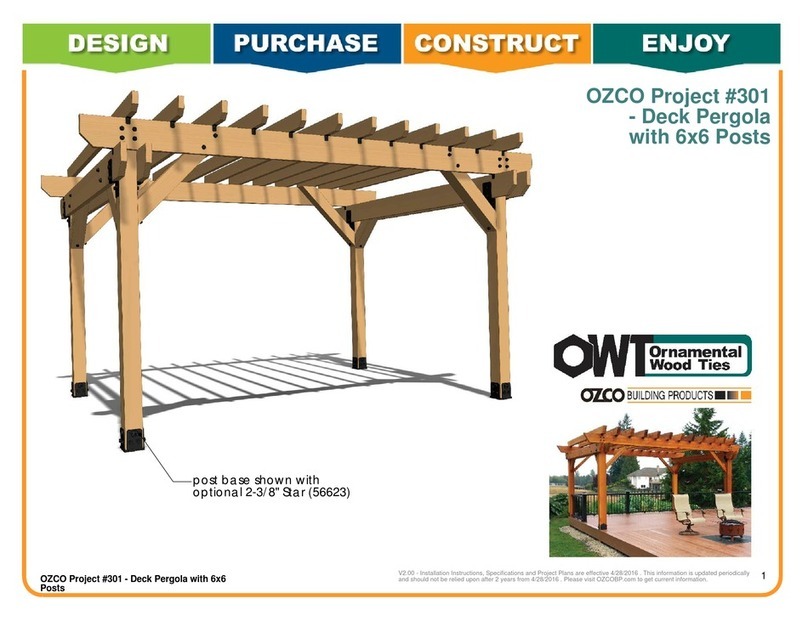
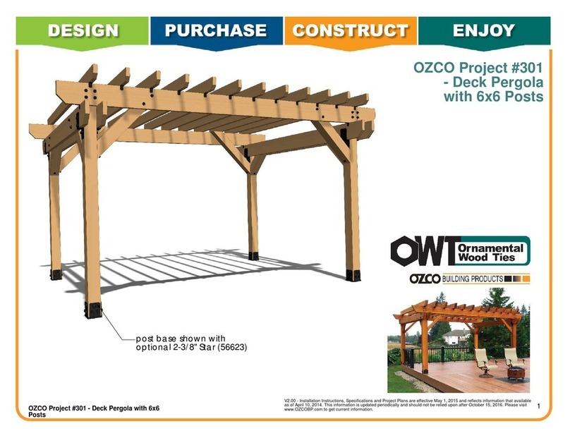
OZCO OWT 301 User manual

OZCO

OZCO OWT 301 User manual

OZCO 210 User manual

OZCO

OZCO 210 User manual

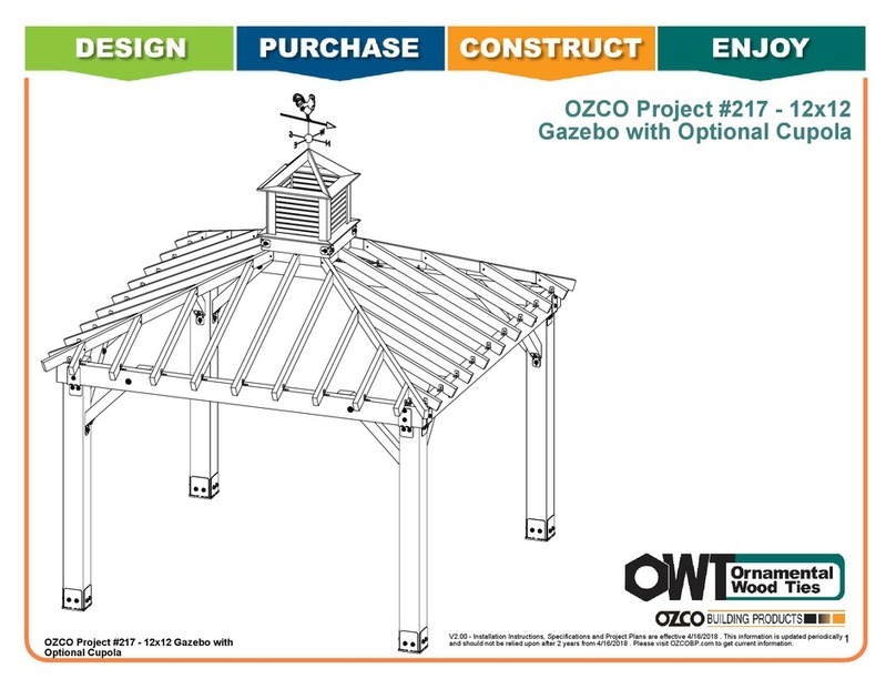
OZCO 217 User manual

OZCO

OZCO 217 User manual

OZCO 301 User manual

OZCO

OZCO 301 User manual

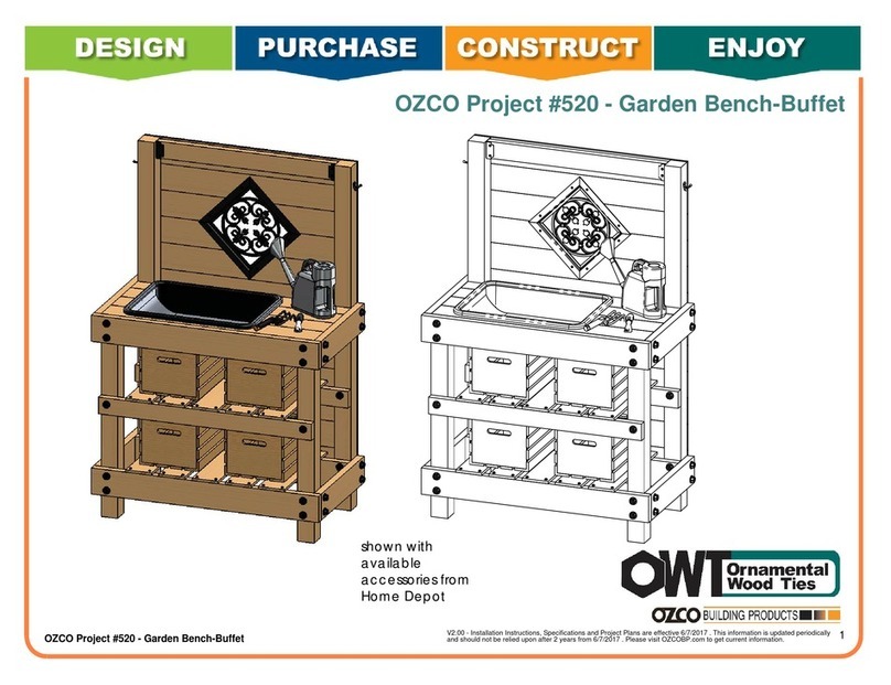
OZCO OWT 520 User manual

OZCO

OZCO OWT 520 User manual

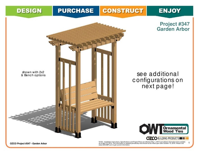
OZCO 347 User manual

OZCO

OZCO 347 User manual

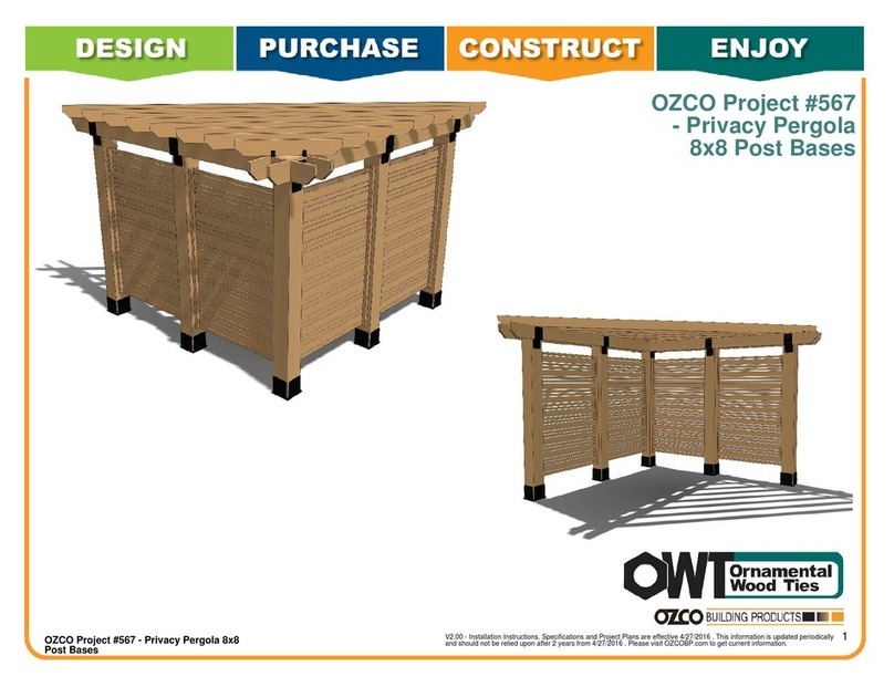
OZCO Project 567 User manual

OZCO

OZCO Project 567 User manual

OZCO 297 User manual

OZCO

OZCO 297 User manual

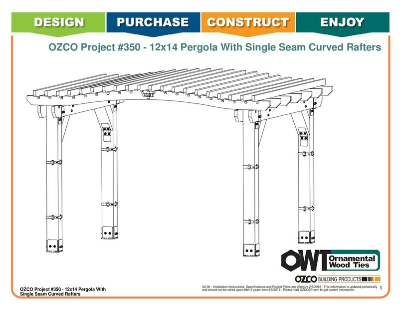
OZCO Project 350 User manual

OZCO

OZCO Project 350 User manual

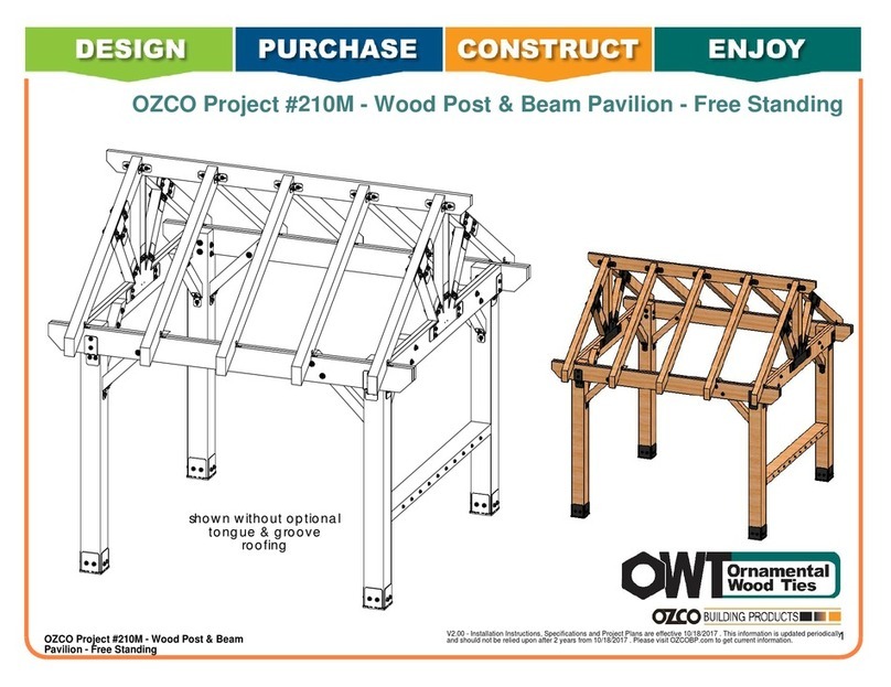
OZCO 210M User manual

OZCO

OZCO 210M User manual

OZCO 214 User manual

OZCO

OZCO 214 User manual

OZCO 325 User manual

OZCO

OZCO 325 User manual

OZCO 347 User manual

OZCO

OZCO 347 User manual

Popular Outdoor Furnishing manuals by other brands
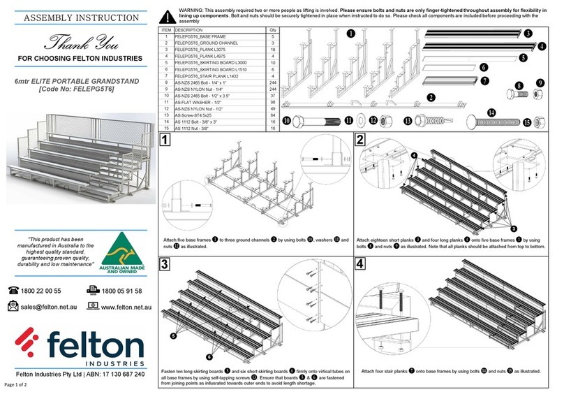
felton industries FELEPG5T6 Assembly instruction
felton industries

felton industries FELEPG5T6 Assembly instruction

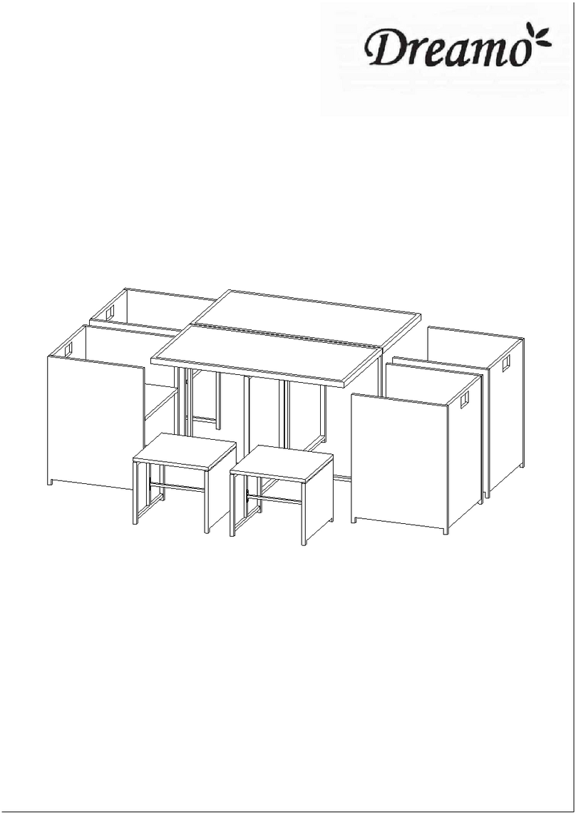
Dreamo OTF-503S quick start guide

Dreamo

Dreamo OTF-503S quick start guide

Garden Furniture Direct Borrowdale Assembly instructions
Garden Furniture Direct

Garden Furniture Direct Borrowdale Assembly instructions

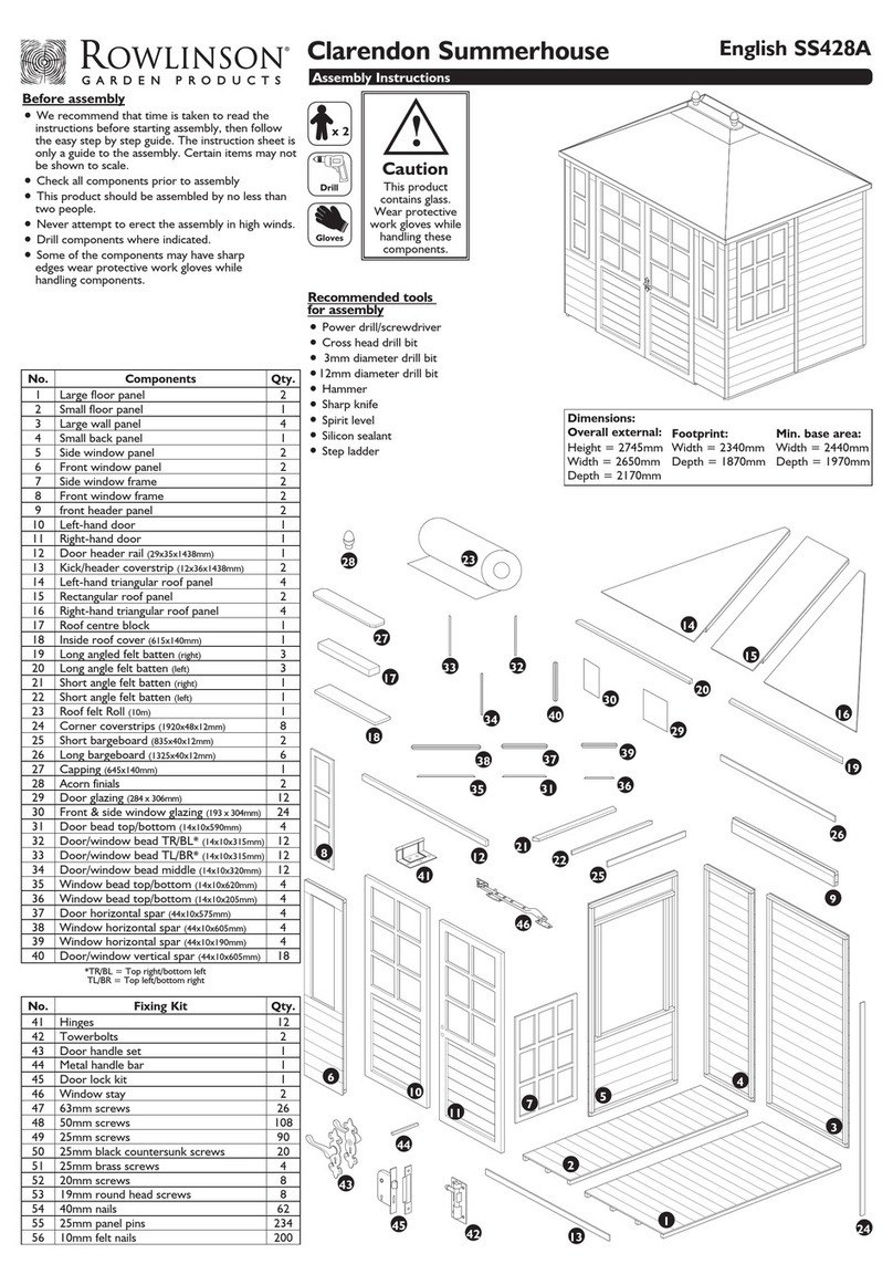
Rowlinson Clarendon Assembly instructions
Rowlinson

Rowlinson Clarendon Assembly instructions

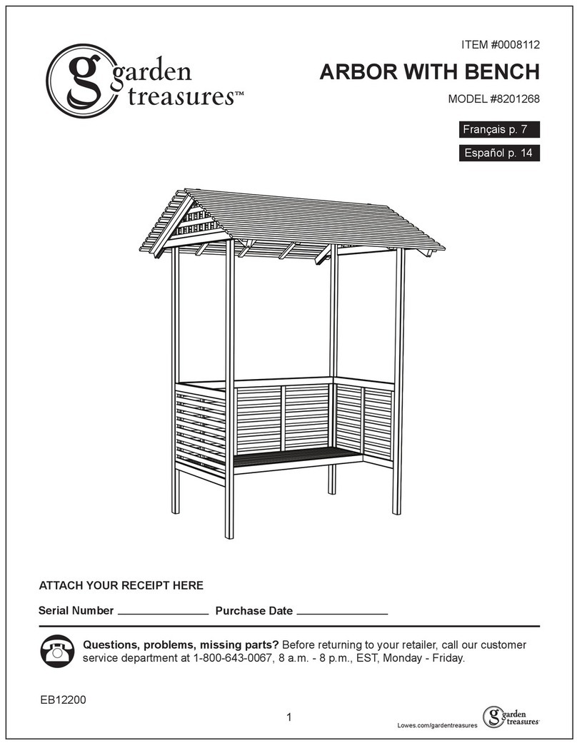
Garden Treasures 8201268 Assembly instructions

Garden Treasures

Garden Treasures 8201268 Assembly instructions

Safavieh Outdoor Marson PAT7062 quick start guide
Safavieh Outdoor

Safavieh Outdoor Marson PAT7062 quick start guide

SSC-LUXon 990070716 Assembly & operating instructions
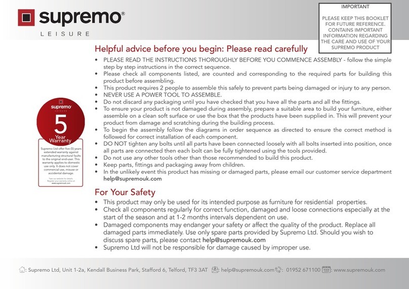
SSC-LUXon

SSC-LUXon 990070716 Assembly & operating instructions

supremo LEISURE 2-Seat Stool 110*40cm Assembly instruction

supremo LEISURE

supremo LEISURE 2-Seat Stool 110*40cm Assembly instruction

Hatteras Hammocks DCA1-K-HH instructions

Hatteras Hammocks

Hatteras Hammocks DCA1-K-HH instructions

Lemeks Palmako PA120-5959 Assembly, installation and maintenance manual

Lemeks

Lemeks Palmako PA120-5959 Assembly, installation and maintenance manual

OLT 24 Assembly manual

OLT

OLT 24 Assembly manual

forest-style HACIENDA 2354 Building instructions

forest-style

forest-style HACIENDA 2354 Building instructions

Courtyard Creations RUS0188-WM Assembly instructions

Courtyard Creations

Courtyard Creations RUS0188-WM Assembly instructions

kingsley-bate MC-55 Assembly instructions

kingsley-bate

kingsley-bate MC-55 Assembly instructions

Weltevree Carrier product manual

Weltevree

Weltevree Carrier product manual

Grange Fencing Elite Arch Assembly instructions

Grange Fencing

Grange Fencing Elite Arch Assembly instructions

Grosfillex AUVENT YR14 Assembly instructions

Grosfillex

Grosfillex AUVENT YR14 Assembly instructions

X-METAL EAGLE 33511 Assembly instructions
X-METAL

X-METAL EAGLE 33511 Assembly instructions
manuals.online logo
manuals.online logoBrands
  • About & Mission
  • Contact us
  • Privacy Policy
  • Terms and Conditions

Copyright 2025 Manuals.Online. All Rights Reserved.