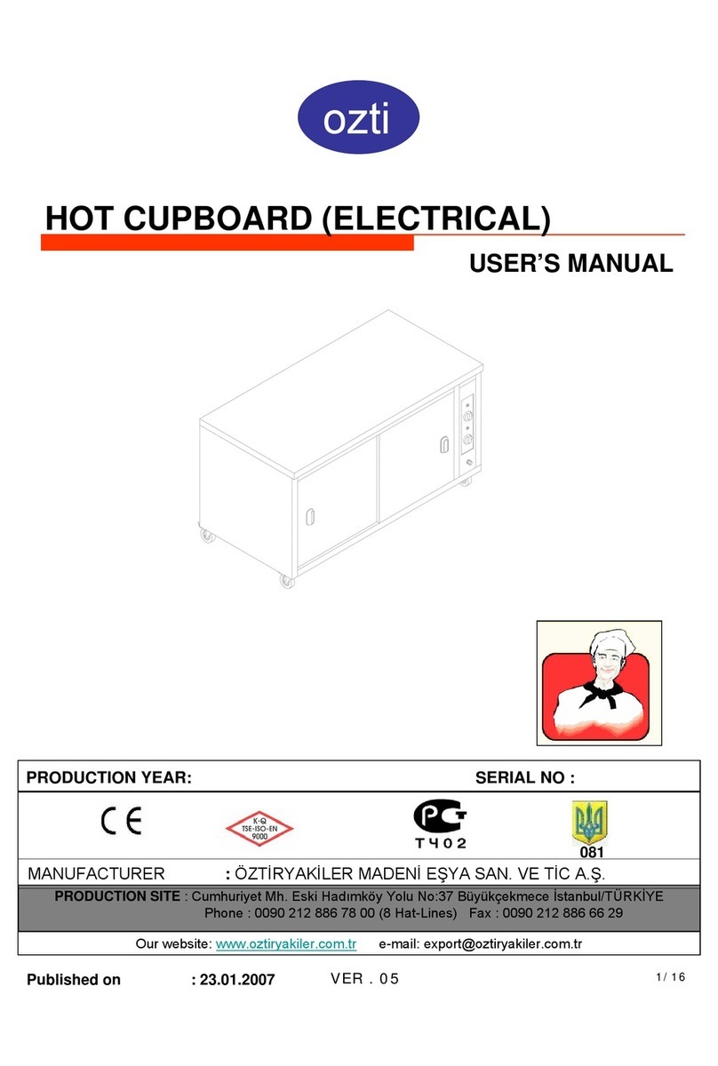
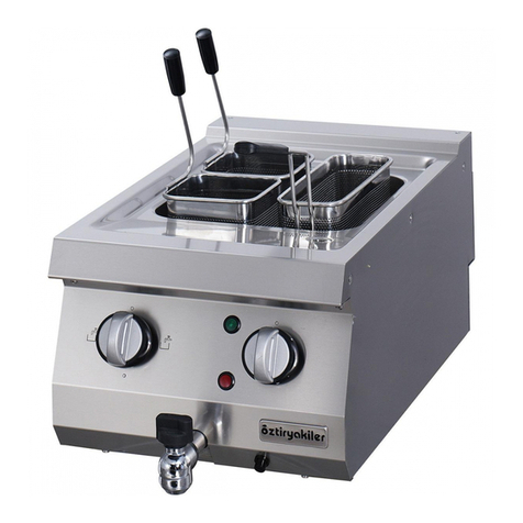
OZTI OBA 70180 User manual

ozti
HEATED UNITS (ELECTRICAL – INDUSTRIAL TYPE)
USER’S MANUAL
OBA 70120
OBA 70180
OBA 14218
OSBI 15894
Published on : 15.05.2005 VER . 05 Page 1 of 12
MANUFACTURER : ÖZTİRYAKİLER MADENİEŞYA SAN. VE TİC A.Ş.
PRODUCTION SITE : Beylikdüzü Eski Hadımköy Yolu 1.Km Büyükçekmece / İstanbul / TURKEY
Phone : 0090 212 886 78 00 (8 Hat-Lines) Fax : 0090 212 886 66 29
Our website: www.oztiryakiler.com.tr E-mail: export@oztiryakiler.com.tr

TABLE OF CONTENTS
PAGE NR. TOPICS
1 COVER PAGE
2 TABLE OF CONTENTS
3 INTRODUCTION
4
TECHNICAL DATA
4
TECHNICAL
DATA
5 ELECTRICAL CIRCUIT DIAGRAM
6 WARNING SIGNS
7 SAFETY DETAILS
8 TRANSPORTING, MOVING AND INSTALLATION
9
CONTROL BOARDS
OPERATION OF THE DEVICE
(1)
9
CONTROL
BOARDS
,
OPERATION
OF
THE
DEVICE
(1)
10 OPERATION OF THE DEVICE (2)
11 CLEAN-UP AND MAINTENANCE
12 TERMS OF GUARANTEE
CAUTION
This device should onl
y
be used in facilities where relevant
2/12
y
standards, laws and safety requirements are complied with

INTRODUCTION
Dear User,
Thank you for purchasing our device and for your reliance upon our company.
Our devices have been used within our customers kitchen, your kitchen in 75
countries. Our devices are produced in compliance with international standards.
Important notice: Please read or ensure that the users read this user’s manual in
order to achieve the desired performance in line with your expectations and to
use your device for long years. Please take the warnings mentioned above into
consideration before calling for service...
Please read and ensure that your operation personnel also reads this
Please
read
and
ensure
that
your
operation
personnel
also
reads
this
user’s manual carefully before installing and using the device. If the
device is operated without reading the user’s manual, the device will not
be covered by the guarantee.
The manual containing information about installation, usage and
maintenance of our product you purchased should be read carefully.
Pl th t l ti t th d i l d
If you are confused or you don’t have enough information
please get in touch with authorized service by phone.
Pl
ease ensure
th
a
t
power supp
l
y connec
ti
ons
t
o
th
e
d
ev
i
ce are a
l
rea
d
y
installed by qualified personnel according to local legislation, before our
authorized service personnel arrives for the installation of the device.
Please keep in mind that, if the service personnel is delayed
at your site, related expenses and delay costs will be charged to
you on hourly basis.
We hope that you will get the best performance from our product…
3/12

P
E
H
NET WEIGHT (Kg)
P
ROTECTION CLASS
POWER SUPPLY
VOLTAGE (V/ Hz)
E
LECTRICAL POWER
(W)
RESISTANCES
CONTROLLING
H
EATED FUNCTIONS
TEMPERATURE
RANGE (°C)
VOLUME M³
MAIN DIMENSIONS
(mm)
CAPACITY
(Lt)
YOUR DEVICE'S
TYPE
220
1 / IP 20
220 – 240 V AC NPE~ /
3 000
2 X 1500 W
DIGITAL THERM. THER
M
VENTILATOR
+65 / +70
3,12
1720X900 1440
1255
OBA 14218 OBA
C
TECH
N
50 Hz
M
OSTAT
C
14218
220 – 240
V
1
DIGITAL TH
E
VE
+
172
OBA 7018
0
N
ICAL D
A
HEAT
E
120
1 / IP 20
V
AC NPE~ / 50 Hz
2 000
X 2000 W
E
RM. THERMOSTAT
NTILATOR
+
65 / +70
1,72
0X900X740
598
0
OBAC 70180
O
A
TA
E
D UNITS
85
1 / IP 20
220 – 240 V A
C
1 500
1 X 1500 W
DIGITAL THERM
VENTILATOR
+65 / +70
1,21
1120X900X740
342
O
BA 70120 OBAC
7
C
NPE~ / 50 Hz
. THERMOSTAT
7
0120
66
1 / IP 21
2 000
2 X 1000 W
STATIC
+70 / +80
2,72
1460X1090X1565
104
OSBI 15894
4/12

VER 10.05
ELECTRICAL CIRCUIT DIAGRAM
VENTILATORS
RESISTANCES
R1
F2
S2
L
PE L
N
PTC
PROBE
R2
F1
220V/50 Hz
M
S2
A1 A2 A3
S1
21 O
A1
S4 S3
3L2 1L1
8
TELEMECANIQUE
LC1K1601M7
1L1
3L2
5L3
21
N
O
A1
A2
6T3
22NO 4T2
2T1
12 11
CONTACTOR 16A
8
C
20(8)
A
E
THERMOSTAT
12
11
7
8
87877
88
7
5
DIXELL XR10
C
G
ITAL THERMOMETR
E
4
OSBI
15894
OBA
14218
OBA
70180
OBA
70120
HEATED UNITS
DI
G
S4
SOCKET 4
14218
70180
SOCKET 1
SOCKET 2
SOCKET 3
LAMP ON/OFF
LAMP
RES 1
S1
S2
S3
A3
L
R1
70120
PE
S3
S4
S1 S2
S1 : PTC PROBE
S3 : VENTILATOR EXIT
S4 RESISTANCE EXIT
S2 : SUPPLY 220V/50 Hz -LAMP (OSBI15894)
F1
F2
VENT. 1
RES. 2
RES
.
1
R1
R2
S4
:
RESISTANCE EXIT
VENT. 2
HEATED UNITS ELECTRICAL DIAGRAM
5/12

WARNING SIGNS
PE
POWER NETWORK GROUNDING GROUNDING
OVERHEAT
POWER
SUPPLY CONNECTION: MONOPHASE
VOLTAGE 220-240 V
GROUNDED
FREQUENCY : 50 Hz
FREQUENCY
:
50
Hz
6/12

SAFETY DETAILS
Any kind of flammable solid and liquid material (cloths, alcohol and
derivatives, petrochemical products, wooden and plastic materials, cutting
blocks, curtains etc.) should never be held near the device.
Never leave the device under direct sunlight. It should be located at
least 40 cm. away from heat sources like ovens, radiators and heaters.
Use can use this device simultaneously together with
other products of ours.
This device should be installed in line with effective regulations and only
be operated in well ventilated places Please refer to the instructions
be
operated
in
well
ventilated
places
.
Please
refer
to
the
instructions
before installing and operating the device.
This device is designed for industrial use and should only be
operated by personnel trained on the device.
The device should not be handled by anyone else except for the
manufacturer or authorized service..
In case of fire or flame in the area where the device is operated, act without
panic, close gas valves (if any),
turn off power switches and use a fire extinguisher.
Never use water to extinguish the fire.
7/12

TRANSPORTING, MOVING AND INSTALLATION
Heated unıts are be delivered as a standard in wooden cases, reinforced by EPS block,
wrapped with stretch film and air bubble protective packing, and wrapped over again with a
second layer of stretch film
The device may be moved with manpower.
Do not hit or drop the device when moving
CHANGING THE LOCATION;
Machines installed by an authorized service CANNOT BE
MOVED ELSEWHERE ITS POWER SUPPLY CABLES
Do
not
hit
or
drop
the
device
when
moving
.
MOVED
ELSEWHERE
,
ITS
POWER
SUPPLY
CABLES
CANNOT BE EXTENDED OR REPLACED except by
an authorized service.
If this device located near to any wall, separation, kitchen furniture,
decorative coating etc. the distance in between should be 20 cm. and if those
are coated with fireproof heat insulating material, the distance should be 5 cm.
It is strong recommended that fire safety protection instructions are observed.
Remove stretch film on the device before installing the device.
After the device is moved to the location where it will be operated, rollers should be set to lock
position. In this way sliding of the trolley is prevented.
Power supply connection of the device should be checked by an eligible electrician, and it
should be connected to a fuse at a maximum height of 170 cm.
Power supply connection should be made using a 30 mA current leakage fuse as a protection
against current leakage danger.
Power installation of the plugs to be used should be grounded by connecting it to a grounding
bar at the nearest
p
anel.
8/12
p

CONTROL BOARDS
HEATED UNITS CONTROL BOARD
0
SIGNAL
ON / OFF
.SET
I
0
DIGITAL
OPERATION OF THE DEVICE (1)
SIGNAL
LAMP
ON
/
OFF
SWITCH
DIGITAL
THERMOMETER
THERMOSTAT
OPERATION OF THE DEVICE (1)
A thermometer with digital thermostat is installed in heated units models. The thermometer with
digital thermostat is set to a relevant default value depending on the model of the device. Never
change this setting. Otherwise you may damage the device. In this case the device will no longer
be covered by the guarantee.
*Turn the device on by setting the on/off switch to the position “1”.
*On the digital thermometer you may see the inner temperature of
the heated unıts.
CAUTION !
NEVER OPERATE YOUR DEVICE
9/12
NEVER
OPERATE
YOUR
DEVICE
WITHOUT GROUND CONNECTION.

OPERATION OF THE DEVICE (2)
CAUTION! :The device should be installed and operated as
described in this user’s manual. If any failure is encountered please
contact our nearest authorized service dealer.
WHEN THE DEVICE HAS A FAILURE ONLYAUTHORIZED
SERVICE DEALERS ARE ALLOWED TO HANDLE
……………………
SERVICE
DEALERS
ARE
ALLOWED
TO
HANDLE
THE DEVICE. IF ANY PERSON OTHER THAN ONLYAUTHORIZED
SERVICE DEALERS HANDLE THE DEVICE, IT WILL NOT BE
COVERED BY THE GUARANTEE.
NEVER ALLOW PEOPLE WHO ARE NOT AUTHORIZED TO
HANDLE THE DEVICE. OTHERWISE PRODUCER COMPANY WILL
NOT BE RESPONSIBLE FOR THE CONSEQUENCES. DURING
MAINTENANCE SERVICE OUR AUTHORIZED SERVICE DEALERS
SHOULD NOT BE PROPOSED TO USE NON-ORIGINAL SPARE
PARTS FOR WHATSOEVER INSTALLING ANY NON
-
ORIGINAL
PARTS
FOR
WHATSOEVER
.
INSTALLING
ANY
NON
-
ORIGINAL
SPARE PART TO THE DEVICE LEAVES THE DEVICE OUT OF
GUARANTEE COVERAGE.
10/12

CLEAN-UP AND MAINTENANCE
After using device, disconnect your device from power supply, by unplugging it or switching
it off, before carrying out periodical clean-up.
Clean your device with liquid dishwashing detergent and a piece of cloth or sponge soaked
in warm water. Then in order to remove detergent residuals rinse it with a piece of cloth
soaked in clear and warm water. Never use abrasive and aggressive cleaning agents like
thinners, bleachers, powder detergents.
For cleaning door gasket, only use warm water and soap. Do not use detergent or other
cleaning agents. Otherwise vacuum feature of the gasket will be harmed.
Be cautious durin
g
the clean-u
p
, that water does not
g
et into control boards.
g
pg
LIFE OF USE
Devices life of use is 10 year if it is used under recommended conditions.
CAUTION! :
Never use combustible, flammable and abrasive
materials for cleaning, like gasoline, gas, thinner,
acid for cleaning.
11/12

TERMS OF GUARANTEE
1- Documents without sales date, factory and sales company approval on, are
not valid. In order to benefit from the guarantee, guarantee document should
be presented.
2- If the device is installed and operated following the instructions in the
installation, maintenance and user's manual, it is warranted for failures
resulting from failures resulting from workmanship and material failures
resulting
from
failures
resulting
from
workmanship
and
material
failures
.
3- The failures within the scope of guarantee, how and where these will be
eliminated, and the way and place of maintenance is determined by
................
4- The guarantee is only valid provided that the guarantee terms and the
instructions in the installation, maintenance and user's manual are fully
complied with The guarantee is only valid for the warranted device and no
complied
with
.
The
guarantee
is
only
valid
for
the
warranted
device
,
and
no
other right or compensation for some other thing may be claimed.
5- If the information about the kind and the type of the device, serial numbers
printed on the guarantee document are scraped, rubbed or changed, then the
guarantee is not valid.
6- The guarantee covers only maintenance and repairing of material or
k hi f il ithi th lid t i d F il d t
wor
k
mans
hi
p
f
a
il
ure w
ithi
n
th
e va
lid
guaran
t
ee per
i
o
d
.
F
a
il
ures an
d
par
t
s
within the scope of the guarantee are repaired and replaced without any
charge. Replaced parts belong to ................
7- The failures occurring in the device may only be handled by service
personnel authorized by ................ If people who are not authorized handle
the device, it will not be covered by the guarantee.
8- Installation should be carried out by authorized service personnel and the
service should be informed about the location change of the device.
9- When any failure occurs during operation, authorized service dealer
should be contacted.
10- Guarantee does not cover failures and damages resulting from loading,
unloadin
g
and shi
pp
in
g
, which are outside the res
p
onsibilit
y
of ................
gppg py
Similarly, failures and damages resulting from external factors are not
covered.
12/12
This manual suits for next models
6
Table of contents
Other OZTI Commercial Food Equipment manuals
Popular Commercial Food Equipment manuals by other brands

Southbend
Southbend BGLT-24 owner's manual

Welbilt
Welbilt Merco MHA Original Instructions Installation, Operation and Maintenance Manual

BaByliss PRO
BaByliss PRO FLASH FX668E manual

Welbilt
Welbilt Merco CrispyMax MCG1027NNN Original Instructions Installation, Operation and Maintenance Manual

Lotus
Lotus FT 712ET 3 Series instructions

Zero Zone
Zero Zone HYBRID RHLC30 Maintenance manual