manuals.online logo
Brands
  1. Home
  2. •
  3. Brands
  4. •
  5. PAC
  6. •
  7. Car Video System
  8. •
  9. PAC VCI-GM3 User manual

PAC VCI-GM3 User manual

Pacic Accessory Corporation - 1502 S. Santa Fe Street, Santa Ana, CA 92705
T[email protected] • www.pac-audio.com
12-4-2007
J1850
Class 2
VPW
Class 2
J1850
100011101111001001101100
111010000110110111001100
Arbitration
EOD
CRC
100011101111001001101100
111010000110110111001100
Class 2
Class 2
J1850
VCI-GM3
Video Camera Interface Kit for the GM Full Size Truck & SUV Navigation Radios
This interface will ONLY work in these vehicles -will NOT work with any other GM navigation radios
DISCLAIMER: Under no circumstances shall the manufacturer or the distributors of the VCI-GM3 parts be held liable for consequential
damages sustained in connection with the VCI-GM3. The manufacturer and it’s distributors will not, nor will they authorize any representative
or any other individual to assume obligation or liability in relation to the VCI-GM3 other than its replacement.
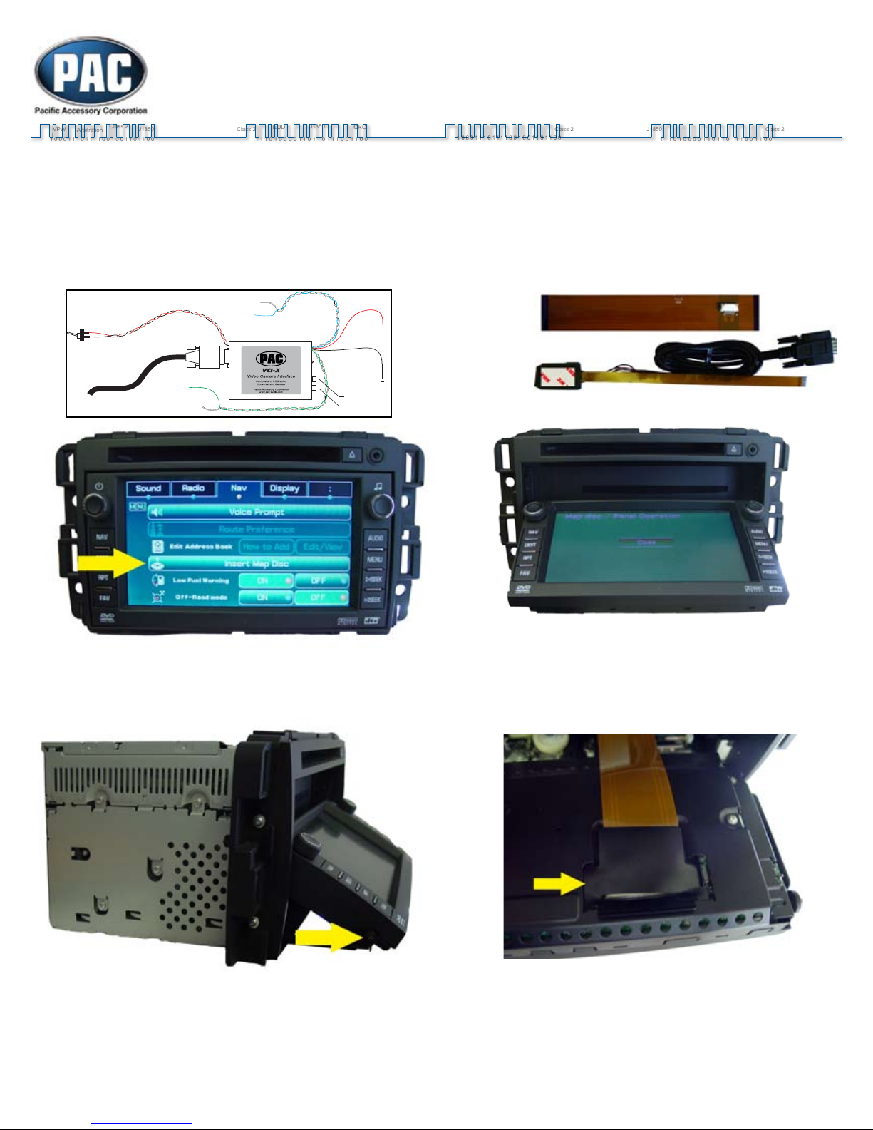
1) With the navigation unit on, press the “Change Map Cover-
age” option under the “Nav” menu and eject the navigation
disc. WARNING! Wait for the Map Disc to eject and set
aside. Failure to eject the Map Disc will cause failure of
the navigation DVD-ROM Drive.
2) Be sure you have removed the Map Disc, then with the display
open, disconnect and remove the navigation unit from the vehicle.
4) Remove the plastic shield covering the factory ribbon cable.
1. Connect the VCI-GM3’s black power wire to chassis ground. Connect the red wire to the vehicles +12 volt accessory. The power wires are the ones coming out
from the DC 12V side of the case. If using the NAV-1129, simply connect the red wire to the retained accessory power and the black wire to the ground output.
2. Connect the VCI-GM3’s Blue Trigger wire to the vehicle’s +12 volt reverse light supply wire. The Reverse wire will show +12 volts when the vehicle is put into
reverse. If using the NAV-1129, simply connect to the reverse output.
3. Connect the Video Back-up Camera’s video output to the VCI-GM3’s Video 2 input. (Optional: The VCI-GM3’s Video 1 input can be used for a second video
backup camera. The toggle switch selects between the radio’s normal display or Video 1 input. Video 2 input has precedence over Video 1 input, when the blue
wire receives +12volts, regardless of the switch position.)
DB9 connector
Red Wire
Black Wire
Video 1 On/Off
Switch
Blue: +12v Reverse
Light Trigger
(VIdeo 2)
White:
ground output
Green:
Parking Brake input (-)
White:
ground output
Video 2
Video 1
RIBBON A
RIBBON B
The installation instructions steps MUST be followed carefully and in order. Failure to follow these
steps may result in damage to the navigation unit!
3) Remove the small Phillips screw on each side of the display. Re-
move the display from the navigation unit
Page 1
8) Route the RIBBON B cable through the side of the
navigation unit with the contacts facing DOWN.
9) Route the Ribbon B cable over the large factory white rib-
bon cable to avoid the gears.
10) Connect the RIBBON B cable to the RIBBON A cable with
the contacts facing UP. A half twist on the Ribbon B will be
necessary for the next step.
6) Remove the two screws from the center cover. Remove the
center cover.
7) Carefully lift up on the release tab and remove the factory
ribbon cable and replace with the Ribbon A cable with the
small connector closest to the navigation unit.
5) Carefully lift up on the release tab and remove the factory
ribbon cable.
Page 2
Pacic Accessory Corporation - 1502 S. Santa Fe Street, Santa Ana, CA 92705
T[email protected] • www.pac-audio.com
Testing the VCI-GM3:
1. Turn the vehicle and radio on. The radio display should show normal information.
* If there is no image on the display, check for correct power connection on the VCI-GM3.
* If the image on the display scrolls across the screen, make sure the ribbon cable is seated in the connector correctly.
2. Temporarily put the vehicle into reverse being careful not to back into anything or anyone. The display screen will change to the video back-
up camera mode. Put vehicle back to Park and the radio display should show normal information.
*If the radio screen information disappears and you get a blank screen when the vehicle is put into reverse, check the video back-up
camera for proper power and video cable connection.
*The camera must be connected to Video 2 Input.
11) Carefully fold and insert the Interface ribbon cable inside
the navigation unit cavity.
12) Assemble the navigation unit in reverse order of steps.
13) Secure the cable to the bottom of the navigation unit.
14) Connect the VCI-GM3’s black power wire to chassis
ground. Connect the red wire to the vehicles +12 volt acces-
sory. The power wires are the ones coming out from the DC
12V side of the case. Connect the DB-9 cable to the VCI-
GM3. Reinstall the navigation unit and verify operation of the
factory navigation unit. Insert the Map Disc.
15) Verify operation of the aftermarket back up camera (and
Video 1 input if applicable).
NOTES:
The factory backup camera (if applicable)
will always have priority when in Reverse.
The factory display will always have pri-
ority when watching a DVD or AUX in Park.
Page 3

Other PAC Car Video System manuals

PAC uPAC-STS User manual

PAC

PAC uPAC-STS User manual

PAC VCI-FRD1 User manual

PAC

PAC VCI-FRD1 User manual

PAC RP4-FD11 Manual

PAC

PAC RP4-FD11 Manual

PAC HEIGH10 User manual

PAC

PAC HEIGH10 User manual

PAC RPK5-GM4102 User manual

PAC

PAC RPK5-GM4102 User manual

PAC VCI-NIS1 User manual

PAC

PAC VCI-NIS1 User manual

Popular Car Video System manuals by other brands

Jensen CAR910X Installation & owner's manual

Jensen

Jensen CAR910X Installation & owner's manual

Gazer CM6507-100S user manual

Gazer

Gazer CM6507-100S user manual

Vizualogic A-2000 owner's manual

Vizualogic

Vizualogic A-2000 owner's manual

Pyle View PLDVD10M Operation manual

Pyle

Pyle View PLDVD10M Operation manual

Audiovox 1187001PL installation instructions

Audiovox

Audiovox 1187001PL installation instructions

GMC Intellilink 2015 owner's manual

GMC

GMC Intellilink 2015 owner's manual

ACV 381094-29-1 installation manual

ACV

ACV 381094-29-1 installation manual

Winnebago OUTLOOK 2007 Operation guide

Winnebago

Winnebago OUTLOOK 2007 Operation guide

Metra Electronics 108-GM1G installation instructions

Metra Electronics

Metra Electronics 108-GM1G installation instructions

Caliber MCD901 operating instructions

Caliber

Caliber MCD901 operating instructions

Pioneer Super Tuner IIID AVH-P5100DVD installation manual

Pioneer

Pioneer Super Tuner IIID AVH-P5100DVD installation manual

Directed Video OHD070 Owner's installation guide

Directed Video

Directed Video OHD070 Owner's installation guide

uvo kia soul user manual

uvo

uvo kia soul user manual

Crutchfield 120 90-3044P Installation kit

Crutchfield

Crutchfield 120 90-3044P Installation kit

Fujitsu Ten Limited FT0091A operating manual

Fujitsu Ten Limited

Fujitsu Ten Limited FT0091A operating manual

Pioneer AVH-2330NEX Operation manual

Pioneer

Pioneer AVH-2330NEX Operation manual

Polaroid PDM-2727M user manual

Polaroid

Polaroid PDM-2727M user manual

Pioneer DMH-WT8600NEX Operation manual

Pioneer

Pioneer DMH-WT8600NEX Operation manual

manuals.online logo
manuals.online logoBrands
  • About & Mission
  • Contact us
  • Privacy Policy
  • Terms and Conditions

Copyright 2025 Manuals.Online. All Rights Reserved.