PG. 4
Pacbrake is a registered trademark of Pacbrake Co.
INLINE MOUNT - FORD 6.0L L5501
4
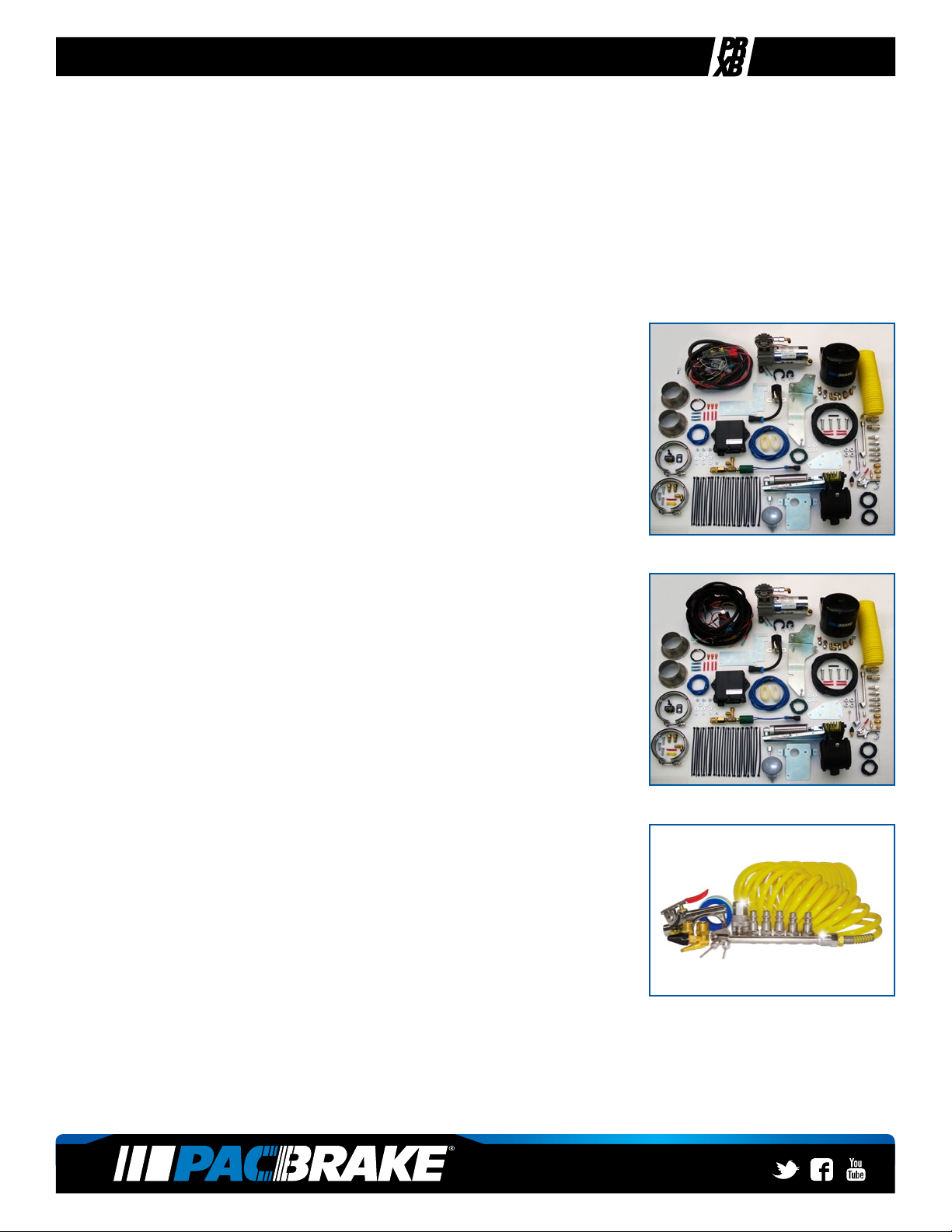
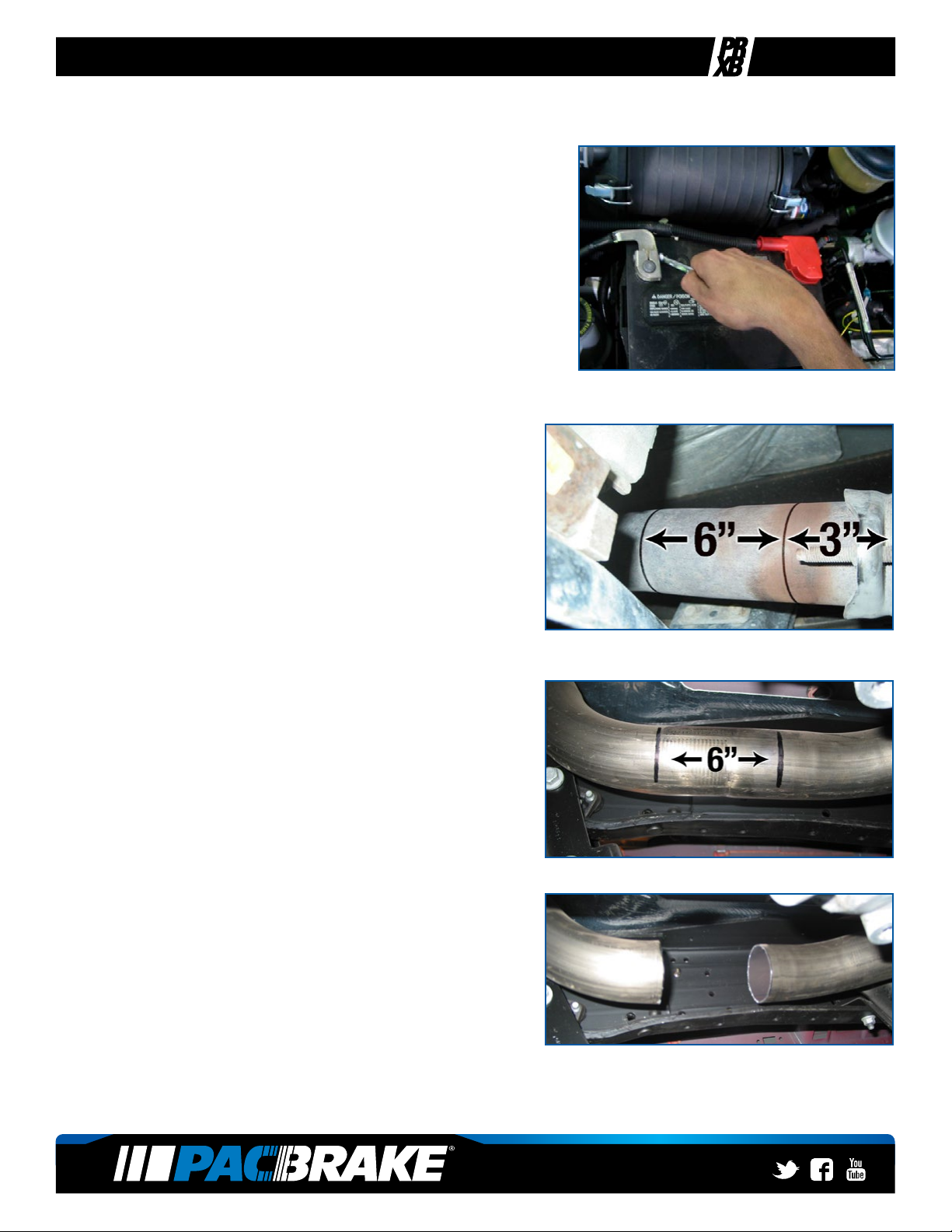
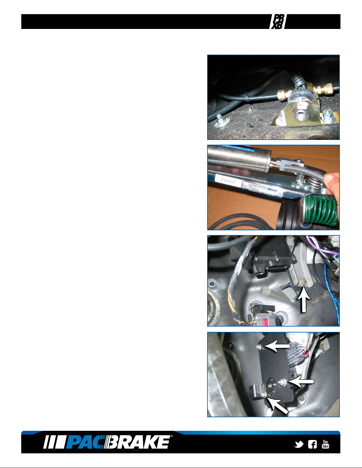
5Using the “V” clamps and adapters provided, loosely
install the adapters onto the Pacbrake - making sure they
are centered on the anges and tight enough that they can
not move prior to being welded. Please note the direction
of exhaust ow through the exhaust brake as shown in
the photo and the sticker on the exhaust brake. Tack weld
the anges to the exhaust system to secure, then remove
the “V” clamps and exhaust brake for nal welding of the
anges. Welding can be done on the inside or the outside
of the pipe, they must be leak free welds. Install the 90
degree tting into the air cylinder using thread sealant.
6Re-install the exhaust system. Loosely install the factory
turbocharger “V” clamp, but do not fully tighten the turbo-
charger “V” clamp at this time (if the exhaust system was
removed for welding). Install the front “V” clamp onto the
exhaust brake ange and adapter with the PRXB regulator
spring located inside the frame rail, make sure the exhaust
brake is centered on the adapter. Torque the “V” clamp to
10 ft-lbs, (14 N•m). Then, loosely install the rear “V” clamp
onto the exhaust brake ange and adapter. (If the header
pipe was removed for welding) center the header pipe
ange to the turbocharger ange, torque the factory “V”
clamp to 72 in-lbs, 6 ft-lbs, (8 N•m). Ensure the exhaust
system is aligned correctly (ange centered) and that ad-
equate clearance exists around the exhaust brake. Then,
torque the rear “V” clamp to 10 ft-lbs, (14 N•m).
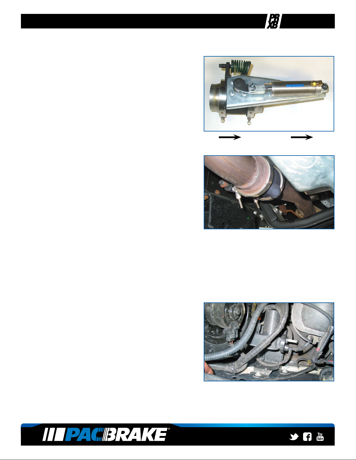
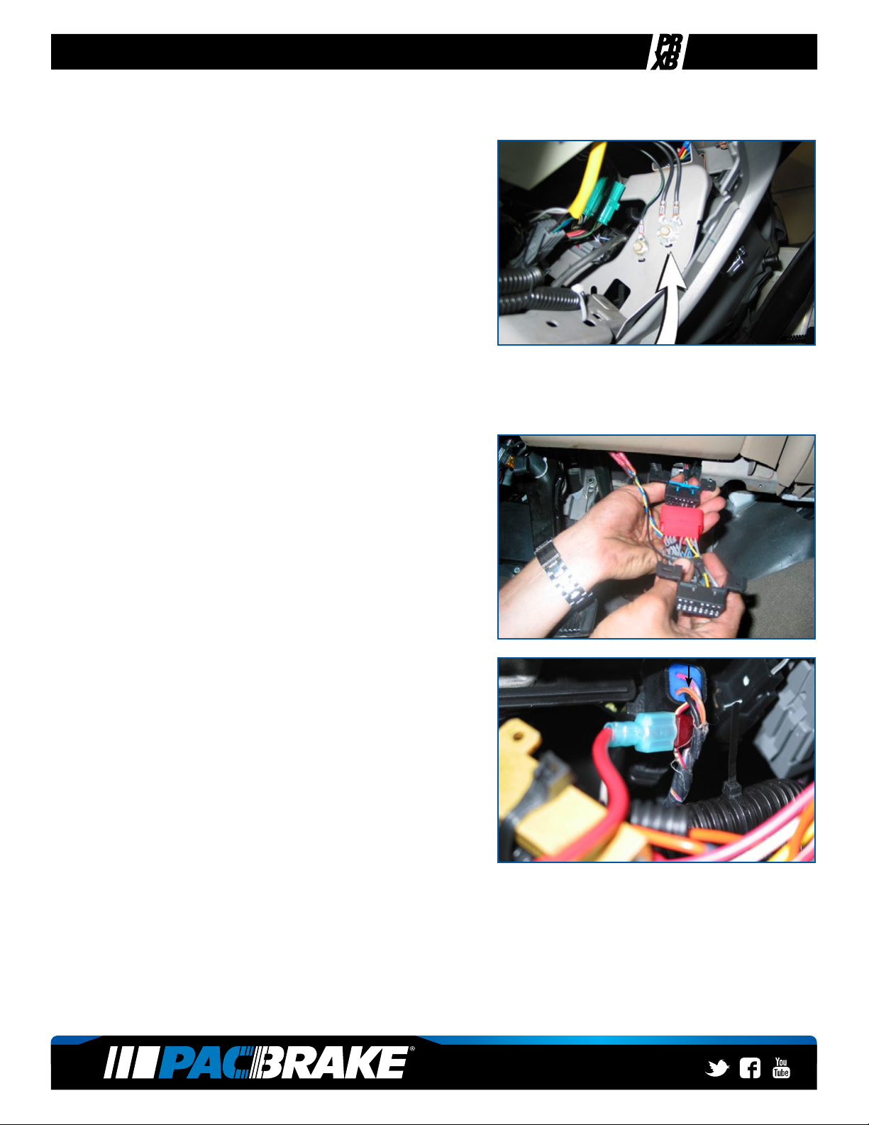
COMPRESSOR/SOLENOID MOUNTING
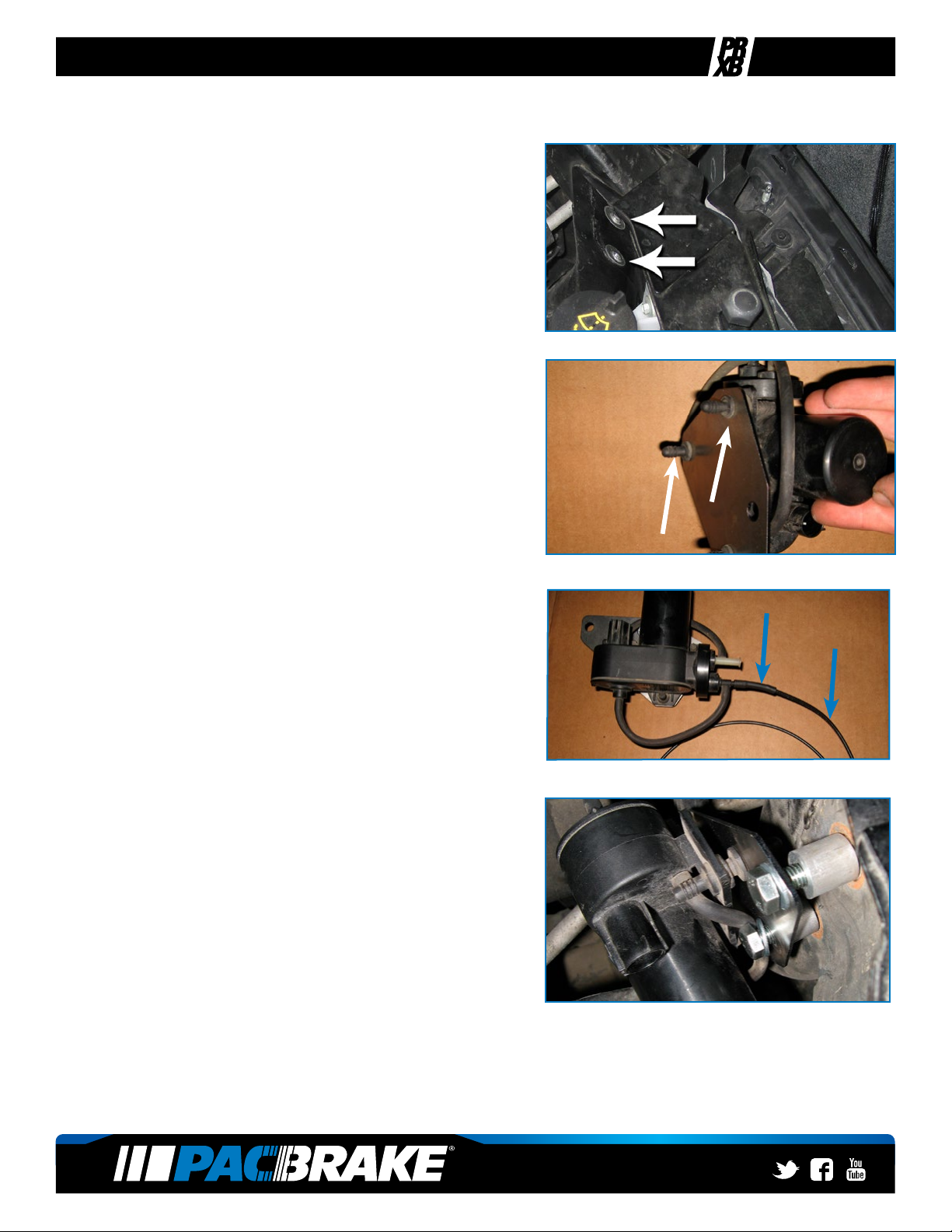
7On the passenger side inner fender, locate and disconnect
the short vacuum hose routed from the vacuum pump to
the vacuum reservoir. Disconnect the electrical connec-
tor of the vacuum pump. Using a 13mm socket, remove
the two bolts attaching the pump and bracket to the inside
fender. Remove the pump from the vehicle.
EXHAUST
FLOW