Pacbrake HP10089 KIT User manual

HP10002/HP10089 KIT
HP10002: Dodge RAM 2500 4WD*
Dodge RAM 3500 4WD*
RAM Mega Cab 1500, 2500 & 3500 4WD*
RAM 3500 Chassis Cab, 2WD/4WD* †
†Installations on these vehicles require an additional kit (HP10136) for vehicles that have a
round axle tube with the breather located approximately 7” from the spring pack.
HP10089: Dodge RAM 2500 2WD*
Dodge RAM 3500 2WD*
RAM Mega Cab 1500, 2500 & 3500 2WD*
* See application guide for proper fitment.
ECN 1-2194

Pacbrake is a registered trademark of Pacbrake Co.
HP10002 & HP10089 AMP AIR SUSPENSION KITS L5682
2
L5682_REV19_ECN1-2194_01.13.2020
A
A
BB
C C
D
D
E
F
T
U
N
NN
N
L
LL
L
JJ
G
I
H
M
P O
K
Q
R
R
S
CAUTION:
This kit includes “push to connect OR
barbed” airline ttings. They require the end
of the airline to be round, square and cleanly
cut to ensure the internal seal will not leak.
The airline must only be cut with a sharp
razor knife or hose cutter.
KIT CONTENTS REQUIRED TOOLS
A
B
C
D
E
F
G
H
I
J
K
L
M
N
O
P
Q
R
S
T
U
Air Springs (2)
Lower Bracket (2)
Upper Frame Bracket (2)
Upper Air Spring Bracket (2)
90° Fitting (2)
Heat Shield (1)
3/8Nylock Nut (12)
3/8Flat Washer (12)
3/8Lock Washer (4)
Gear Clamp #48-102 (2)
3/8NF x 7/8Capscrews (Upper Spring) (4)
4 Axle Strap (4)
3/8-16 x 3 Carriage Bolt (8)
Roll Plate (4)
M10 x 35 Capscrews (4)
3/8- 16 x 11/4” Carriage Bolt (4)
Clamp (1)
Lower Air Spring Support Bracket (2)
3/8” NF x 1” Capscrews (Lower Spring) (4)
Air Line/Valve Assembly (1)
Tie Strap (6)
HP10000 (HP10002 kits)
HP10083 (HP10089 kits)
HP0022
HP1147
HP1148
HP1100
HP0012
HP1000
C653
C18007
HP1001
HP1002
HP0021
HP1003
HP10054
HP1134
HP1149
HP1006
HP0093
HP1183
HP1344
C11618
•7/16, 1/2”, 9/16 open end or box wrenches
•17mm open end wrench
•Adjustable Wrench
•Torque Wrench
•3/8,
9/16,
1/2deep well sockets
•Heavy Duty Drill
•3/8and 5/16 drill bits (very sharp)
•3/8Nut Driver
•Hose Cutter, Razor Blade or Sharp Knife
•Pipe Thread Sealant
•Air Compressor /Compressed Air Source
•Hoist or Floor Jack
•Safety Stands
•Safety Glasses
•Spray Bottle with Dish Soap/Water

Pacbrake is a registered trademark of Pacbrake Co.
HP10002 & HP10089 AMP AIR SUSPENSION KITS L5682
3
L5682_REV19_ECN1-2194_01.13.2020
Thank you and congratulations for your purchase of a AMP air suspension kit.
IMPORTANT: The air suspension kit will not increase the GVWR (gross vehicle weight rating), as this is determined by the axle rating. Do not exceed the
maximum capacity listed by the vehicle manufacturer.
Before starting, ensure the application information is correct for the make, model and year of the vehicle you are installing it on. Please read the entire
installation manual prior to starting the installation to ensure you can complete it once started.
If installing a 10002 in a RAM 3500 Chassis Cab truck, install the appropriate Breather Relocation Kit (10136 for 2007-2018, 10349 for 2019+) BEFORE
installing the 10002 air springs. Follow the instructions provided within the 10136/10349 to do so. Installing the 10136/10349 Breather Relocation Kit is
only required for 3500 Chassis Cab vehicles with round axle tubes having the breather located approximately 7” from the drivers side leaf spring pack.
Pacbrake recommends using a good quality anti-seize on all fasteners, this will reduce the chances of corrosion of the fasteners, and help facilitate
removal if required at a later date.
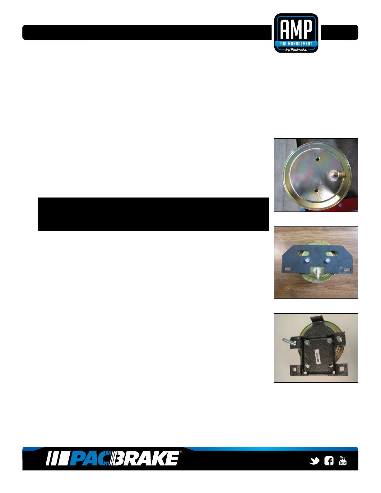
1
THE UPPER ROLL PLATE
Place the upper roll plate (with the rounded side towards the air spring) on the
top of the air spring (top being the end with the air inlet port). Install the air tting
supplied, use thread sealant to prevent air leaks. Repeat on the other air spring.
2
THE UPPER ROLL PLATE
NOTE: This kit contains 4 pieces of a 3/8”NF x 7/8” capscrews (upper bracket),
and 4 pieces of a 3/8”NF x 1” capscrews (lower bracket). It is Imperative that
these capscrews be identied before proceeding. Installing the incorrect capscrew
WILL cause the air spring to leak (and this will NOT be covered under warranty).
Place the upper air spring mounting bracket on top of the air spring and roll plate.
The upper air spring mounting bracket is identied by the two 3/8” holes next to the
air tting cut out. Using 2 - 3/8” NF x 7/8” capscrews provided, fasten the bracket to
the air spring. Torque both capscrews to 20 ft-lbs, 27 N•m.
3
THE LOWER PLATE & BRACKET
Place the lower roll plate on the bottom of the air spring (rounded side towards the
air spring). Locate the lower air spring mounting brackets and support plates.
Place the lower support bracket on the roll plate with the bent leg to the same
side as the air tting in the upper end of the air spring. The bent leg of the support
bracket must be pointing away from the air spring. Align the two holes in the
bracket with those in the roll plate and air spring.
The lower bracket is designed to be installed oset to the lower end of the air
spring. The oset must be opposite the air tting installed in Step 1. Two 3 long
arriage bolts must be installed into the two elongated holes of the lower bracket
before it can be fastened to the air spring and roll plate. Using 2 - 3/8NF x 1” long
capscrews and lock washers provided, fasten the bracket to the air spring. Torque
both capscrews to 20 ft-lbs, 27 N•m.
NOTE: The lower brackets have 2 extra sets of holes to t various applications, use only the mounting holes
shown in the photo for this application. When installed on the vehicle the lower bracket will be oset towards the
outside of the vehicle and the air inlet tting should be towards the inside of the vehicle.
Repeat steps 1 - 3 on the other air spring
STEP 3
STEP 2
STEP 1

Pacbrake is a registered trademark of Pacbrake Co.
HP10002 & HP10089 AMP AIR SUSPENSION KITS L5682
4
L5682_REV19_ECN1-2194_01.13.2020
4
INSTALLATION ON THE VEHICLE
1 Raise the vehicle enough for a comfortable working height with a oor jack and
support the axle with jack stands.
2 Remove the jounce bumpers on both sides.
5
ATTACH THE UPPER BRACKET
Using the M10 x 35 capscrews provided, fasten the upper air spring mounting
bracket to the frame as shown in the photo. Torque the capscrews to 30 ft-lbs, 40
N•m. The upper brackets must be installed to the jounce bracket with the air inlet
tting cutout and rectangular holes in the bracket facing towards the center of the
vehicle.
6
INSTALLING THE AIR SPRING
Insert the air spring between the jounce bumper mounting plate and the axle tube.
Some vehicles may require the frame to be jacked up slightly to attain clearance.
NOTE: Air ttings must be positioned towards the center of the vehicle. The outer
rear carriage bolts may be installed now. The outboard rear carriage bolt on the
passengers side must be between the brake line and the axle tube. On the drivers
side both rear carriage bolts must be in between the brake line and the axle tube.
Passenger’s side is shown in photo.
Loosely install two of the 11/4 long carriage bolts through both upper mounting
plates. Install the at washers and nylock nuts provided. Loosely install the axle
straps to the carriage bolts using the at washers and nylock nuts provided.
7
ADJUSTING THE AIR SPRING
Adjust the air spring assembly to the upper bracket by moving the lower bracket
on the axle tube to ensure the air spring is correctly aligned, as shown in the Air
Spring Alignment diagram below:
AIR SPRING ALIGNMENT
INCORRECT CORRECT
DOUBLE CONVOLUTED 4 WHEEL
DRIVE AIR SPRINGS SHOWN HERE
STEP 4
STEP 5
STEP 7
STEP 6

Pacbrake is a registered trademark of Pacbrake Co.
HP10002 & HP10089 AMP AIR SUSPENSION KITS L5682
5
L5682_REV19_ECN1-2194_01.13.2020
STEP 8
STEP 9
STEP 10
STEP 11
8
CHECK THE CLEARENCE
Check the clearance around the brake lines and carriage bolts. The brake line
must not touch the carriage bolts, adjust if necessary. Once alignment of the air
spring is correct, tighten the two 11/4carriage bolts to 20 ft-lbs 27 N•m, and then
torque the 4 axle strap carriage bolt nuts also to 20 ft-lbs 27 N•m.
Repeat on the other air spring.
NOTE: Install the clamp provided to secure the emergency brake cable to the
driver side front 11/4 carriage bolt.
9
INSTALL THE HEAT SHIELD
Bend the two center tabs of the heat shield supplied for fastening to the exhaust
pipe as shown.
Attach the heat shield with the gear clamps supplied to the exhaust pipe to protect
the air spring.
10 Provided in the basic air spring kit are two ll valves, the most common place to
install them is to replace the license plate fasteners with the ll valves. Alternative-
ly, two holes can be drilled in a convenient location. Install one airline provided,
route the nylon hose to an air spring tting, cut the hose and connect to the air
spring tting. Repeat with the other ll valve. Secure airlines with the tie-straps
provided away from moving items and heat sources.
If an in cab ination kit is being installed, follow the instructions provided with it.
NOTE: This kit contains push to connect ttings, using scissors or wire cutters
to cut the nylon airline will distort the line and cause the connection to leak. THE
AIRLINE MUST BE CUT OFF SQUARELY WITH A SHARP RAZOR KNIFE.
Moisten the end of the airline prior to inserting it into the tting and push it in
until it stops.
IMPORTANT! Double check all the fasteners are torqued to specication.
11
LEAK CHECK
Inate both the air springs to 90 PSI, use a dish soap and water mixture on all
airline connections to detect air leaks. Repair as necessary and retest. Inate your
air springs to a predetermined value, then the following day recheck the pressure,
if one or both the air springs have lost pressure a leak is present, the leak must be
repaired, then retest until no leaks exist.
SPECIAL NOTE:
Retorque all the fasteners after the rst 500 miles of driving.

Pacbrake is a registered trademark of Pacbrake Co.
HP10002 & HP10089 AMP AIR SUSPENSION KITS L5682
6
L5682_REV19_ECN1-2194_01.13.2020
OPTIONAL ACCESSORIES
Pacbrake oers an optional dual needle air gauge to monitor the pressure in each air spring from the vehicles cab.
Pacbrake oers a full line of air compressors, air tanks and solenoids to control your air spring system.
OPERATING YOUR VEHICLE WITH PACBRAKE AIR SUSPENSION
Air springs have minimum and maximum pressure requirements, never operate your vehicle with less then 10 PSI
in the air spring and never inate the air springs over 100 PSI, damage to the air springs will result.
Check the air pressure in the air springs daily for the rst couple of days to ensure a leak does not develop. The
air springs are designed to maintain the vehicles stock ride height with a load. Do not use the air springs as a
means to lift the vehicle with no load, a rough ride will result.
SERVICING YOUR VEHICLE WITH PACBRAKE AIR SUSPENSION
When lifting the vehicle with a oor jack or hoist on the frame never allow the air spring to limit the travel of the
axle, try to always jack the vehicle on the axle. Suspending the axle with the air spring limiting the axle travel will
damage the air spring and void the air spring warranty.
WARRANTY
To be eligible for warranty, owner must submit their warranty card or (register online at pacbrake.com/warranty)
within 30 days of purchase date.
NOTE: The owners warranty will be void if air springs run with less than the minimum of 10 PSI.
This manual suits for next models
1
Table of contents
Other Pacbrake Automobile Accessories manuals
Popular Automobile Accessories manuals by other brands

ULTIMATE SPEED
ULTIMATE SPEED 279746 Assembly and Safety Advice

SSV Works
SSV Works DF-F65 manual

ULTIMATE SPEED
ULTIMATE SPEED CARBON Assembly and Safety Advice

Witter
Witter F174 Fitting instructions

WeatherTech
WeatherTech No-Drill installation instructions

TAUBENREUTHER
TAUBENREUTHER 1-336050 Installation instruction