Pacbrake is a registered trademark of Pacbrake Co. 1
HP10216 AMP AIR SUSPENSION KIT L6360
ECN 1-1789
L6360_Rev4_17.07.2018
KIT CONTENTS
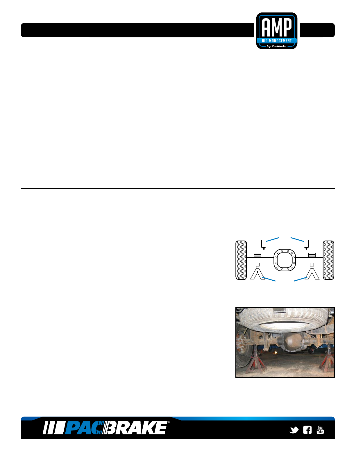
REQUIRED TOOLS
• Hoist or Floor Jacks
• Safety Stands
• Safety Glasses
• Torque Wrench
• Standard Open-End Combo
Wrenches
• Ratchet
• Metric and Standard Sockets
• 7⁄32" Allen Wrench (socket if available)
• 5⁄16" Drill Bit (very sharp)
• Heavy Duty Drill
• Hose Cutter, Razor Blade or
Sharp Knife
• Air Compressor or Compressed
Air Source
• Spray Bottle with Dish Soap & Water
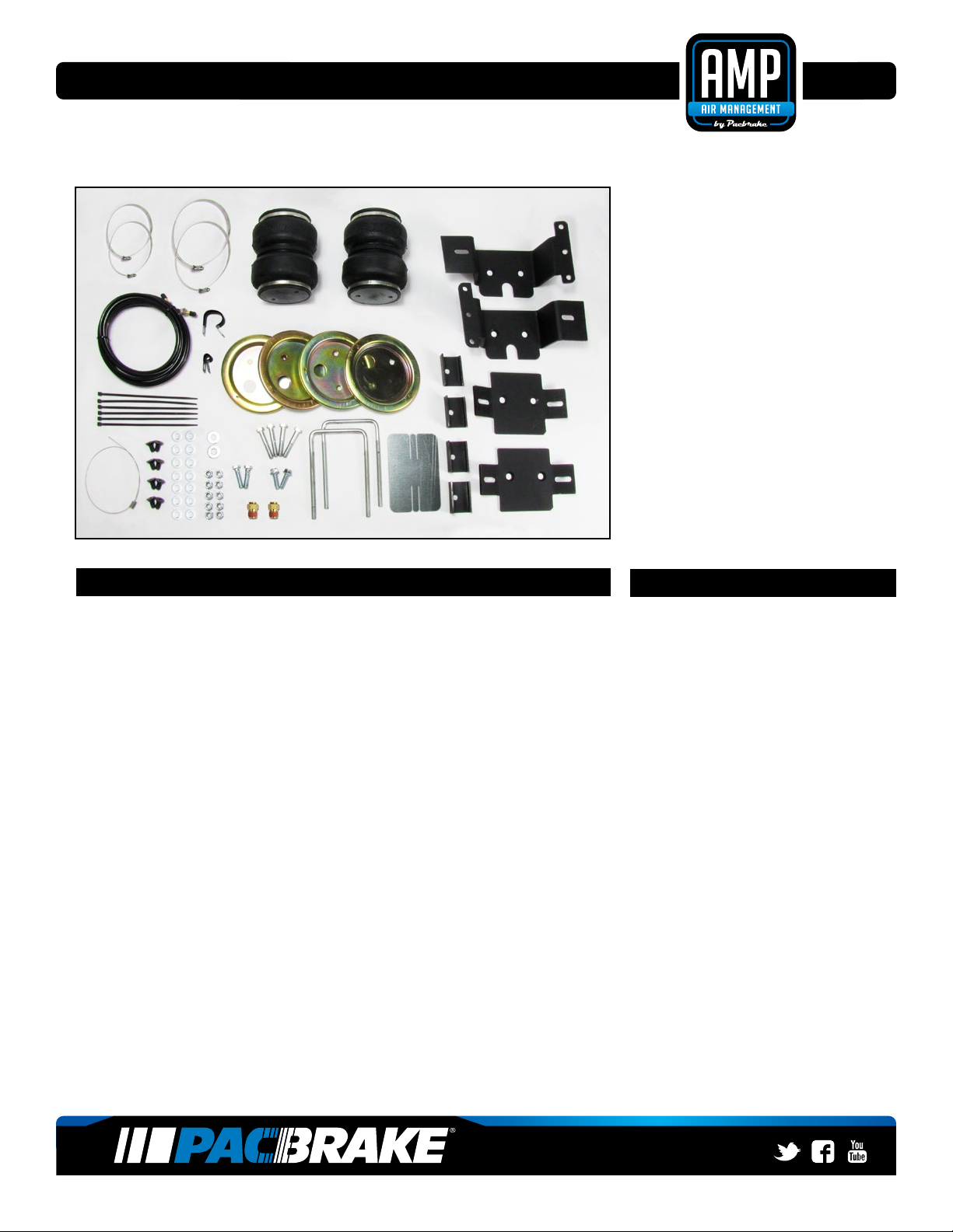
Make sure all the items shown in
the photo are provided in your kit
before starting the installation.
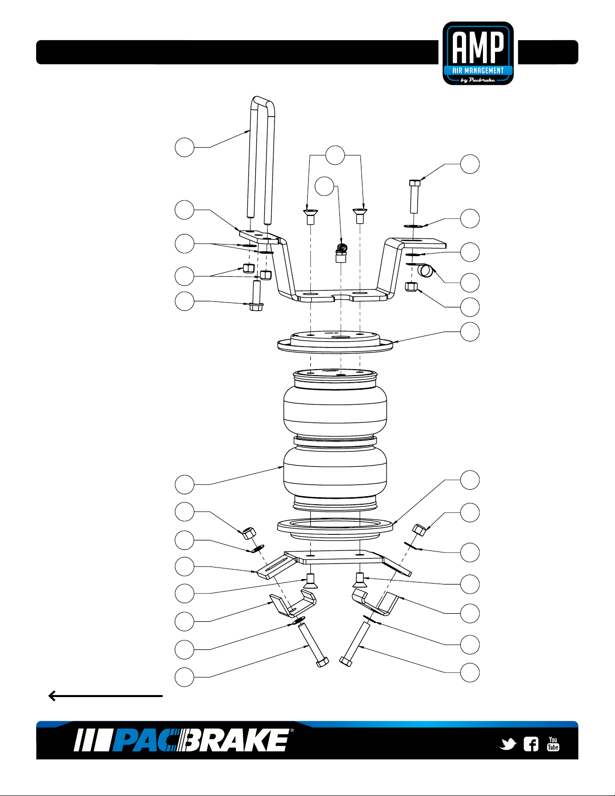
KIT CONTENTS
A Air Spring (2) HP10000D
B Upper Bracket Driver Side (1) HP1432
C Upper Bracket Passenger Side (1) HP1431
D Lower Bracket (2) HP1433
E J Clamp (4) HP1434
F SUB GROUP (1) HP10217
F1 Capscrew, Countersunk (8) HP1008
F2 Bolt 3⁄8x 1 ½ NC (2) C18018
F3 Flat Washer 3⁄8" (2) C18006
F4 Flat washer 3⁄8" SAE (14) C653
F6 Screw Hex Cap 3⁄8"-16 (4) HP1416
F7 Nut Nyloc 3⁄8"-16 (10) HP1000
F8 U-Bolt (2) HP1331
F9 Airline Hose Assembly (1) HP1344
F10 Bolt, Self-Tapping 3 (2) HP1078
F11 Cable Clamp 5⁄8" (2) HP1435
F12 Cable Clamp 1" (1) HP1436
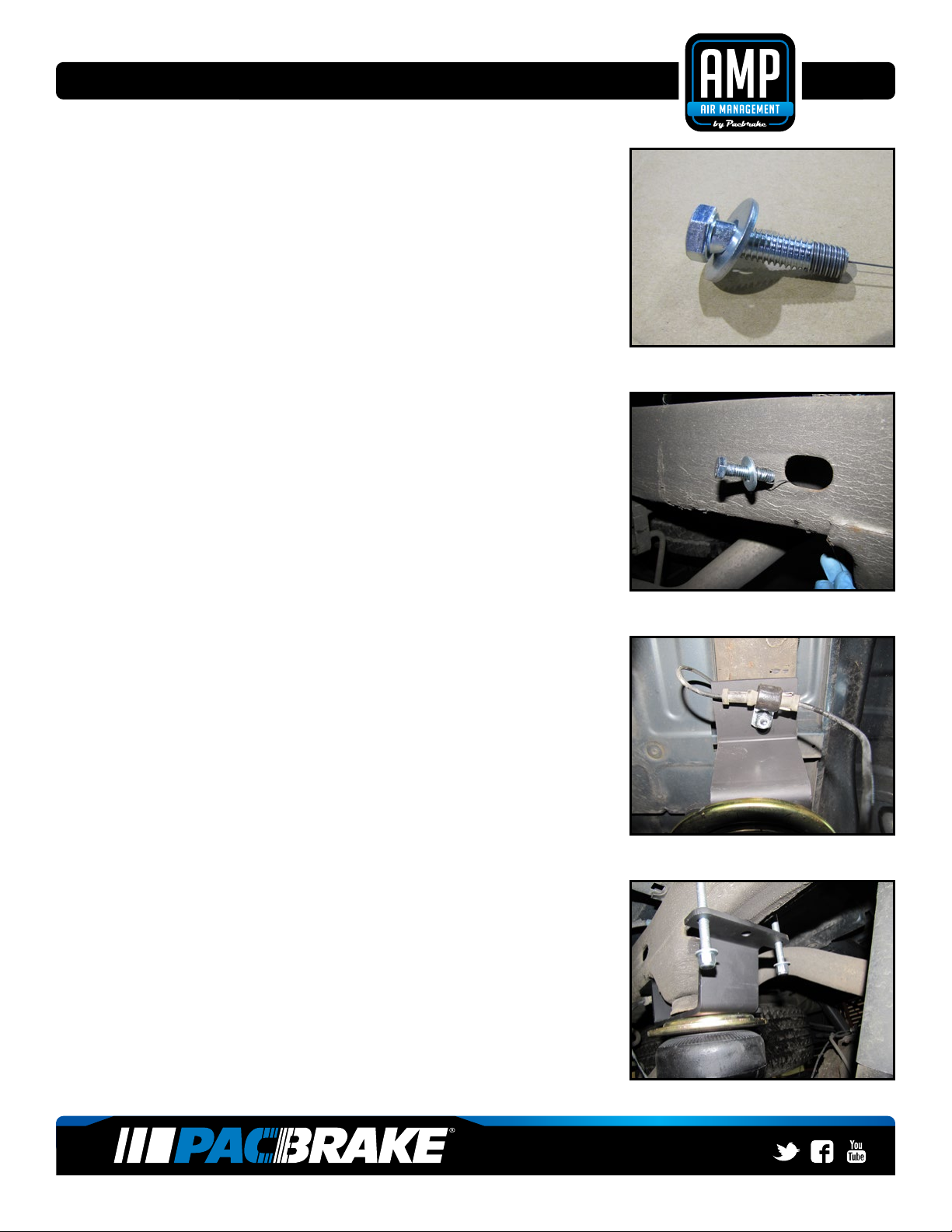
F14 Bolt Leader Tool (1) Hp1440
F15 Heat Shield (1) HP0012
F16 Worm Gear Ring Clamp (2½" - 4 ½") (2) HP1001
F17 Worm Gear Ring Clamp (4½" - 6½") (2) HP1377
H AIR SPRING SUB GROUP (1) HP10180
H1 Fitting, Brass, Push (2) HP1099
H2 Tywrap (6) C11618
H3 Roll Plate (4) HP10054
A
B
C
E
D
D
F12
F11
F2
F10
F6
F17
F16
H15
F14
H1
H2
H3
F9
F8
F7F4
F3
F1